 |
||
Software
To generate the video signal, we used Prof. Land's video generation code. The code draws a 128x100 raster using an NTSC rate, non-interlaced signal. Each line is started exactly every 1018 cycles while drawing the lines visible on the screen (30-230). Because the interrupt that does the drawing must be entered with precise timing, modifying the raster can only occur while the beam is not drawing on the screen, lines 231-30. This severely limits the amount of processing that can be done each cycle. Quite often the drawing of large objects must be split across several frames. The code provided by Prof. Land allows points, lines, characters, and strings to be drawn.
To draw the 8x8 pixel symbols and characters used in Duck Hunt, we had to add a character drawing function that handled this size. Characters and symbols are stored in an array stored in flash and are drawn by setting individual pixels high or low. Almost three quarters of the total flash memory on the chip was used with character maps and game coding. This, along with the fact that we can't have any other interrupts running besides the video one required us to use a second microcontroller to run the sound and music.
The algorithm for the Zapper gun allows us to detect not only whether or not a duck is hit, but also which of the two ducks was shot while not producing a false positive by shooting the scenery or text. The first stage is entered when the trigger is pulled and only continues if a white object is being pointed at. The first duck is then blacked out if it is alive at the time, otherwise we skip right to duck two if it is alive. After the duck is blacked out, we must pause one frame before drawing it white again. This is because the detection signal is pulsed rather than a steady high or low. This wait time gives the gun a chance to see the black screen without the possibility of the white flag being set before the duck is drawn black on the screen. We then check to see if the gun is now pointing at black and if it is, we redraw the duck white and wait a frame to ensure the gun triggers on the white. If the transition from white to black to white is completed, we are ensured that the first duck was shot and we then begin the death sequence. If the first duck was not hit, we then begin the same 5 stage process with the second duck.
The port attached to the controller is polled every quarter second to test for input. It is not polled every frame to allow the user time to press buttons B and C to switch the duck under control and release them without too much jitter. Pressing buttons B and C alone will speed up or slow down the duck. Pressing a direction on the controller's direction pad will send the duck under control in that direction.
Because of the limited time we have to do calculations between frames, only one duck can be moved in every other frame. The duck moves by being un-drawn at its current location and redrawn at a newly calculated position. While the velocity and true position are fixed point numbers, the ducks are only drawn at whole number pixel values. If the duck is being controlled by the second player, the velocity is determined by the controller input. When there is only one player, the ducks' flight is determined by a randomly selected direction every two seconds. If time or bullets run out, the ducks fly straight up and disappear at the top of the screen. Ducks hang in a shot pose for half a second and then fall to the grass when shot.
When the duck hits a wall of the screen, it is reflected off at the incident angle. When two ducks collide, they are both reflected in the direction they came from. Collision detection is implemented by checking each of the four corners of the duck (with a few pixels padding) with the position of the other duck. If they are inside the other's bounding box, they are sent back the way they came. Collision detection is performed by one duck when they are both alive and by the living duck when the other is in the process of dying. Because of the way the ducks are drawn, we could not allow them to pass through each other without flickering as they overlapped.
The screens between rounds are drawn and un-drawn in stages because we cannot draw more than a few 8x8 symbols per frame without artifacts. The game starts in level 0 and a trigger pull prompts the shooter to pick the number of players. Shooting duck one selects one player mode and duck two selects two player mode. You then pick one or two ducks in the same manner. Following this, the game is set up and the screen is un-drawn in stages. You then get a pre-round screen that indicates level, round, and points needed to advance levels. Each duck is worth the level number. At the end of the round, the dog is drawn in stages holding up the number of ducks killed if all for that round were killed. If one or more ducks escaped, the dog is drawn and moves up and down to simulate laughing. From there, the game conditions are checked at the end of the level. The game continues for ten levels or until the score does not meet the required score for that level. An appropriate win/lose screen is displayed and the high score is stored in eeprom. In two player mode, a graphic indicates the winner and loser and their respective scores. The screen is then cleared and the game is reset to level 0.
The sound program worked by playing a certain sound based on the values of 5 input pins on the MCU. Three pins were reserved for sound states that the game on the first MCU could take on while the two other pins were toggle pins that generated a gunshot and duck falling sound. The sound states were all sounds that would never be played simultaneously with each other. These sounds included: no sound, menu music, flapping sound, dog laugh, win music, and lose music. The sound program was classified sounds into two types. There was one type of sound that depended on outputting different frequencies of a sine wave (menu music, win music, lose music, dog laugh, duck falling) and there was another type of sound that depended on outputting samples from flash (gunshot sound, flapping sound). Whenever a pure sine wave based sound was needed, TCCR0 was set to fast PWM mode and there was no prescaler on the clock. Whenever a sound from flash was needed, TCCR0 was set to fast PWM mode but there was a prescaler of 8 on the clock. The sound bytes loaded into flash couldn't be loaded as one large array or a compiler error would result. The arrays had to be split up into smaller arrays in flash. The sound sample values were set equal to OCR0 and updated on overflow.
For the music, a time base had to be created. The duration of some notes were longer than others depending on the "song" that was being played. When the time condition was met, the increment value was updated according to the new frequency corresponding to the note of the song.
The gunshot and duck falling sounds were put on separate toggle pins because these sounds were usually played during the flapping sounds. These toggle pins were actually edge triggered external interrupts (INT0 and INT1) that set a flag every time the first MCU toggled the pin. When the flag was set, the second MCU would play the appropriate sound and clear the flag. Once the toggle sound was done playing, the program would revert back to playing the sound of the current state based on the three input pins. The toggle sounds had priority over the state sounds and would always play even if a state sound was currently being played.
Hardware
The most important piece of hardware in the game was the Zapper gun. There are two circuits in the gun, one for the trigger and one for light detection. To capture the signals from these circuits, we attached them to the external interrupt pins but did not enable the interrupts. By doing this we were able to get an edge triggered flag to read as needed because polling was not a viable option. This method was decided on after consulting with Prof. Land.
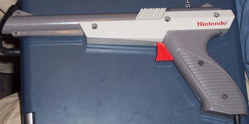
The trigger circuit is a switch that closes as the trigger is being pulled back. By the time it clicks and makes the distinctive sound the switch has already opened back up. The gun output level is held at 5V through a 5kOhm pull-up resistor. When the switch closes, the port pin then sees a transition from high to low. Once the switch opens it returns to high while charging a capacitor.
The light sensing circuit consists of a phototransistor, filters, and pulse shaping elements. Because of the filter, the gun only detects white light from a standard television. The gun emits a periodic 5V square pulse when pointed at white objects on the TV screen. The width of the pulse is dependent on how much white is within the focus of the gun barrel, with the maximum being about 2.5mS long. This output of the gun was attached to a pull-up resistor and an op-amp voltage follower to unload the port.
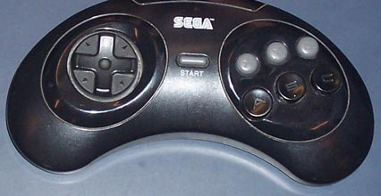
The Sega Genesis controller was a straight-forward device to interface with. It takes in power, ground, and an input for the select line. Because we only needed the directional pad and two buttons, we were able to leave the select line at one value instead of pulsing it to change which buttons were active. We could then poll the direction pad and B and C buttons every quarter second to control the duck. Pressing the B and C buttons simultaneously would change the duck currently being controlled.
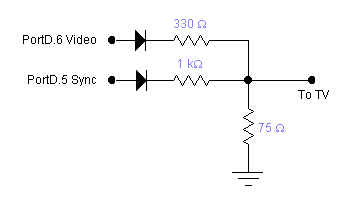
To produce the video signal, a digital to analog converter was needed. This was the same circuit as used in the lunar lander lab. The resistor network creates the appropriate voltages for white and black screen drawing, as well as sync pulses (1V, .3V, 0V respectively). The circuit diagram is taken from the course webpage.
The hardware of the sound was responsible for converting the pulse of varying width into an appropriate analog voltage signal value. This was accomplished by using and integrator that consisted of a resistor of 3K and capacitor of 2.2 nF. When the sound circuit was tested in lab, we heard an unpleasant high frequency pitch at around 7500 Hz. We had to pass the sound through four lowpass filters with a cutoff frequency of 6830 Hz in order to attenuate the high frequency noise just enough. The resistor and capacitor values chosen were 2330 ohms and .01 microfarads, respectively. The resistor values couldn't be too high or else there would be too much power loss. The sound program was programmed into a prototype board that we soldered together. The output was on Port B3 and the inputs were on Ports D2 - D6. These were connected to the first MCU on the STK500.