UrPuzzle:
"Gimme pic, show u puzzle "

By:
Song Shuai and Ho-Chin Yang
Contents
- Introduction
- High Level Design
- Hardware Design
- Software Design
- Results
- Conclusions
- Ethics
- Appendix A: Commented Code
- Appendix B: Overall Schematic
- Appendix C: Parts List
- Appendix D: Tasks
- Appendix E: References
- Pictures
Introduction
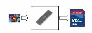
Our project
is a puzzle game that uses images stored in a SD memory card as the source
image. The MCU will read the image from the card through the connector and
transform it into 8-bit color that the program can show on TV. The image will
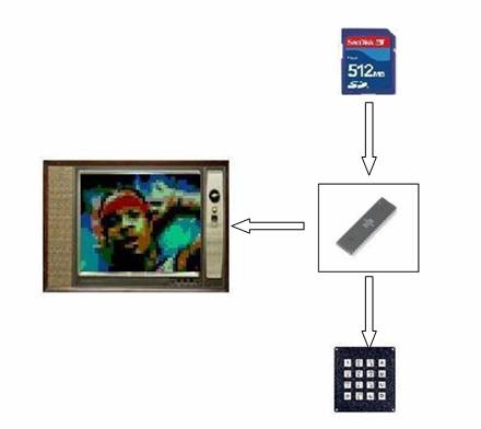
be split into several pieces and arranged in disorder randomly. The goal of the game is move all the pieces back into right
positions, by using the keypad to control the movement of each piece. The game
is displayed on the NTSC color TV.
High
Level Design
Rationale:
As the idea of digital home is
getting hot, television is becoming the center of our home, instead of just a
kit of playing television programs. Although not enough budgets are available
for us to develop applications on digital TV, the most important thing is
realizing our ideas. Thus, we consider the possibility of developing an album
on color television. In our application, users can browse their pictures stored
in SD card. Furthermore, we use the pictures to create a puzzle game.
Logical Structure:
Preprocess: write the bmp files manually
In execution:
Hardware/Software Tradeoffs:
Mega32 has only 2KB SRAM but the
buffer that holds TV pixels already use up 64 (width) x 48 (height) / 2
(byte/pixel) = 1536 bytes. Therefore, the available memory we can use is very
limited. It turns out that we are forced to use the screen buffer for reading
pictures from SD card.
Also, the speed of communication is
also the key limitation. We have to split some tasks into smaller chunks so
that the display will not be affected. When users change pictures, SPI is used
to communicate with SD card, but the time of transmission affects the display
significantly, even if we only read one byte at a time.
The display of color TV is very time
sensitive.
Standards:
This project integrates several
standards:
· BMP
· SD Card
· NTSC
BMP
format
BMP is a bitmap image format developed by
Microsoft and commonly used in Windows operating systems. As BMP has a simple
structure, it is straightforward for us to handle BMP, so we choose it as our
first supporting file format. Each BMP file contains:
|
Bitmap-file header |
Information about the type, size, and layout of a
file. This project only recognizes 48 x 36 pictures. |
|
Bitmap-information header |
Information about the dimensions, compression type,
and the color format for the bitmap. This project only recognizes 24-bit,
uncompressed file. |
|
Color table |
An array of RGBQUAD structures. We do not use
this. |
|
Bitmap bytes |
The actual image data, represented by consecutive
rows, or "scan lines," of the bitmap. Left-to-right order. |
As BMP is developed by Microsoft, little
Endian order is used. Thus, reading an integer needs reverse its order. For
example, a 32-bit integer Byte3 Byte2 Byte1 Byte0 is allocated as:
Base
address + 0 Byte0
Base
address + 1 Byte1
Base
address + 2 Byte2
Base
address + 3 Byte3
Note:
We found that the way that BMP stores Bitmap bytes is upside-down.
The reason we choose SD card is that we can use SPI (Serial Peripheral Interface)
to bridge SD card and MCU. There are two SD operating modes: SD and SPI, . The
one we use is SPI. The pin and connection is as follows:
We refer to Video page written by
Glen Williamson to understand the color TV.
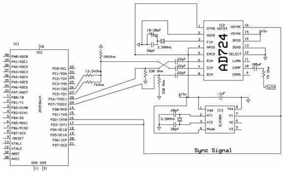
Hardware Design
Here is the picture of our hardware.
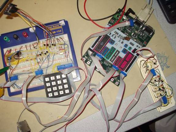
We build up the circuit for following components:
· Color TV
· SD Card
· Keypad
Color TV:
Alan Levy color TV is the platform of our
project. And we fixed a little bug of the schematic on the webpage.
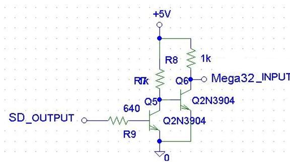
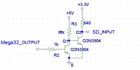
We connect lines to the step-up and step-down
circuits. The design of these circuits is taken from Peter D’Antonio and Daniel
Riiff’s project.
Keypad:
We connect the keypad to PORTA.
Software Design
· Video
· SD Card
· Game
· Keypad
Video
The screen is allocated as the
following diagram:
· 64 x 48 : Screen area
· 48 x 36 : Image area
There are 64 x 48 = 3072 pixels on the screen. As
one byte stores two pixels, there are 1536 bytes in total responsible for
displaying screen.
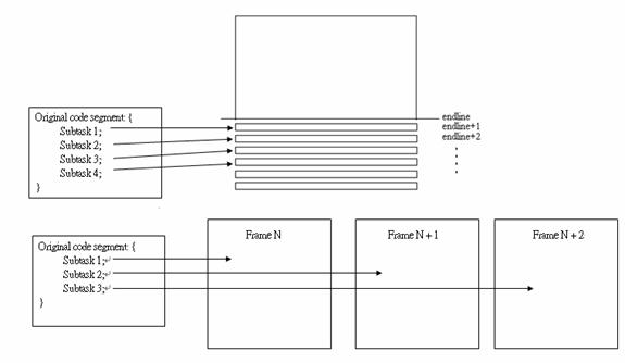
The resources, such as time and memory, are very
limited. We have to split our program of displaying into several segments and
execute them in several lines, even several frames. For example, the following
codes are excerpted from the part that displays a TV frame:
Also, we have to write functions and call them for
some longer code segments because we did not see Mega32 supports far jump. By calling
and returning from functions, several execution cycles are wasted.
SD Card:
In fact, the features associated with the SD card
are a series of downturn.
At
first, we planed to use FAT, the file system which is created by Microsoft and
used by most of digital cameras, to be the file system in SD card. With the
file system, users could store images directly by taking pictures with DC.
Before we could communicate with SD card without errors and then access the
FAT, the best way of writing programs for the card is to use a card reader and
access the card on Windows. However, we recognized that this would require us
to deal with USB, another big task. Because of time constraint, we did not want
to spend time doing work that is irrelevant to microcontroller, so we gave up
delivering this feature. Thus, we have to store images into SD card by an
additional program through Mega32.
Then, we fixed our plan to write images sequentially in the card so
that we can upgrade easily in the future. However, we stuck into unreliable
read and write operations of the card for a long time, so we were forced to
write the processed pixels that can be brought onto the screen directly. The
method we use will be mentioned in the following section.
Image Writer:
As the bottleneck we faced in SD
card, we have to use separate programs to write pictures into SD card. First,
we use a program on Windows to read the normal image file and read its color
bytes and compress each R, G and B three bytes into a nibble and write out as a
text file.
As a result, the format we use in the
SD card is sequentially
Game:
We split the image into 12 sub-images
and randomly shuffle them (So there may be no way to put them back).
The state-transition diagram is as
following:
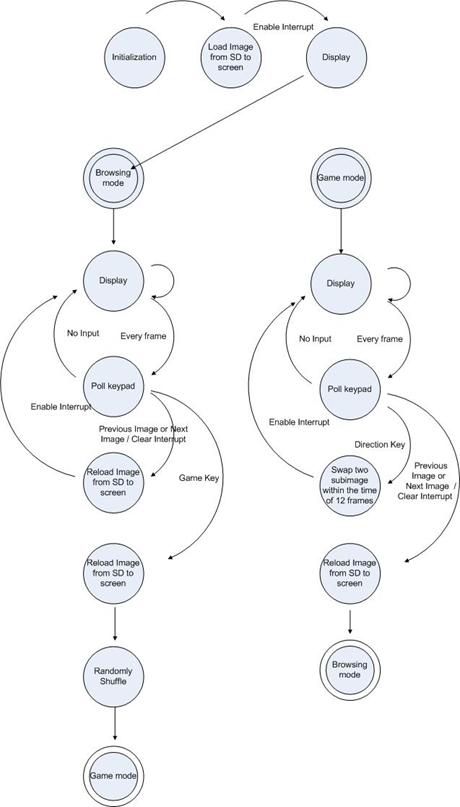
We swap sub-images in the period of
12 frames because in this way we do not have to debounce the keypad.
Keypad:
We do not have to debounce keypad as
we used to do in previous lab assignments because we poll the buttons every
frame.
Results
Our image displaying suffers from
shifting vertical positions after reset and reload. Some colors are also quiet
correctly displayed. Except for these TV bugs, our game runs very smoothly.
Conclusions
Although the functions are below our
expectations, we deliver a good game by complying with several standards.
Ethics
We make sure we followed the
IEEE Code of Ethics throughout this project.
5.
To improve the understanding of technology, its
appropriate application, and potential consequences
The goal of our project is to
integrate several standards we never handled before. The NTSC TV is going to
its tombstone, but it will exist forever, so our application will be useful
forever.
6.
To maintain and improve our technical competence and to
undertake technological tasks for others only if qualified by training or
experience, or after full disclosure of pertinent limitations
Building this system
really helped us to know many standards.
7.
To seek, accept, and offer honest criticism of
technical work, to acknowledge and correct errors, and to credit properly the
contributions of others
We are open-minded
to accept any error we made.
Appendix B: Schematic
The following is an overview of the connections to the MCU. Specific circuits can be found in the hardware section.
Appendix C: Parts List
|
Part |
Cost ($) |
|
Atmel Mega32 |
8 |
|
STK 500 |
15 |
|
RGB to NTSC converter AD724JR |
Sample from Analog Device |
|
Sync generator ELM 304 |
10 |
|
Color TV |
10 |
|
Keypad |
6 |
|
Breadboard |
Self-owned |
|
SD Memory card |
Self-owned |
|
SD card connector |
Donated by a friend of Ho-Chin |
|
Total: |
$49.0 |
Therefore, we stayed well below the $50 limit in the project guidelines.
Appendix D:
Tasks
Most parts of the project were done by both members of the group. The following are the specific tasks involved:
- Writing the Code: Both
- Testing the Code: Both
- Ordering and buying parts for the project: Ho-Chin
- Designing the Hardware: Both
- Testing the Hardware: Both
- Soldering the Parts: Song
- Integration and final testing: Both
- Writing the Report: Both
- Creating the webpage: Both
Appendix E: References
1. We would first like to thank
2. Data Sheets:
http://instruct1.cit.cornell.edu/courses/ee476/AtmelStuff/full32.pdf
3. Vendor Sites:
4. Online
References:
http://instruct1.cit.cornell.edu/courses/ee476/FinalProjects/s2000/peterdan/final.htm