MCU CHESS
INTRODUCTION | HIGH LEVEL DESIGN | HARDWARE DESIGN | SOFTWARE DESIGN
RESULTS | CONCLUSION | PICTURES | APPENDICES
The purpose of this project was to program the microcontroller with AI to play chess and move a chess piece on its own. This project was essentially two projects one in, program the microcontroller to play intelligent chess and design a system whereby the microcontroller could move a piece by sending signals to hardware.
The decision to work on this project was a compromise between two very different ideas. The first idea was to create a robot that would respond to commands given by the microcontroller. The second idea was to program the microcontroller to play a game. We knew that the rules for creating games were the input had to be unique, but by combining chess and a robot we were able to create a unique output. The microcontroller would play chess and move its own pieces.
The way the program works is simple. The microcontroller will play chess with the user through the serial port. The microcontroller initializes the chess board in memory and lets the user make the first move. After the user has made his or her move, the microcontroller will send control signals to the chess board to move the correct piece. After the piece is moved, the microcontroller will then play its turn and move the chess piece.
The project was divided into two main portions, the hardware and software portion. The software portion consisted of creating the chess AI and interfacing the microcontroller with the chess board. The hardware portion consisted of creating the ‘robot’ to move the chess piece.
The software side was responsible for the chess AI and for sending the correct control signals to the hardware circuitry. The chess AI adapted a well known system for choosing chess moves. The main algorithm is called alpha-beta pruning and essentially tries to make the best possible move assuming that the opponent will also try to play their best move. The other portion of the software controls the PWM signals to the motors and the signals to turn on the solenoid and the electromagnet.
The hardware portion was further broken down into two parts. One half consisted of creating the actual chess board and mechanics of the ‘robot’ to move the piece. The second was the circuitry required to operate the ‘robot.’
The chess board:
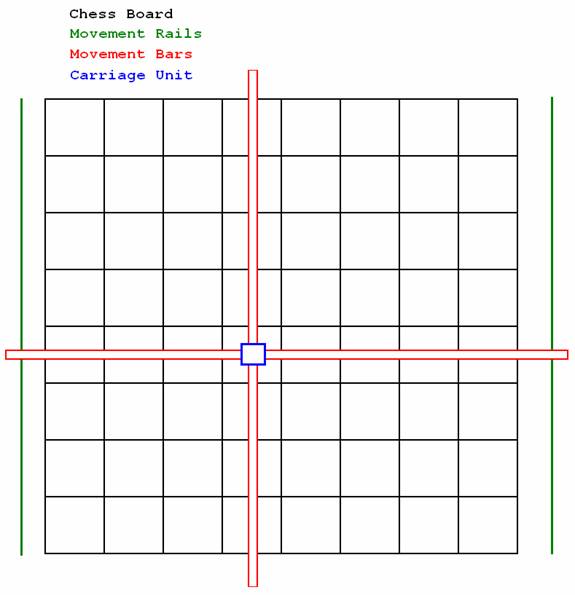
We created an X-Y motor system to make moving the chess pieces easier. A total of four motors were positioned on each side of the chess board and pulled a bar towards or away from itself. With motors on opposite ends working in sync, each end of a bar was moved along the designated axis. A carriage unit located where the two bars intersect contained a combined solenoid/electromagnet unit that picked up the chess pieces. By correctly positioning each bar, the point at which they met would be the chess piece that needed moving as well as the carriage unit.
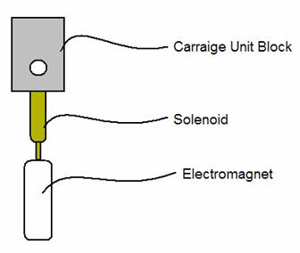
The carriage unit is a block of metal with two perpendicular holes for each bar. The bottom of the carriage unit has a solenoid attached to it. At the end of the solenoid core, an electromagnet is attached. The electromagnet turns on to capture chess pieces while the solenoid turns on to lift the electromagnet and chess piece for movement.
The hardware circuitry:
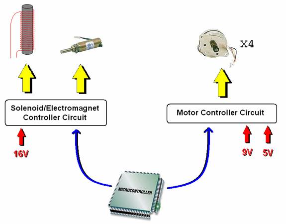
The microcontroller sent a total of 6 signals to the hardware circuitry. Two signals go to the solenoid/electromagnet controller circuit and four go to the motor controller circuit. The individual controller circuits are described in more detail in the hardware design section below.
The Chess Board:
Our original idea was to create a linear version of the stepper motor. We would place electromagnets at each position along a line and turn them on and off to attract a magnet. This idea was killed by cost and material availability issues. We instead settled for creating linear motion with regular stepper motors.
All four sides of the chess board have a movement rail. The movement rail consists of a motor, free spinning wheel, rubber band track, and a movement bar end. The movement bar stretches across the chess board onto the movement rail on the opposite end.
The movement rail setup is shown below:
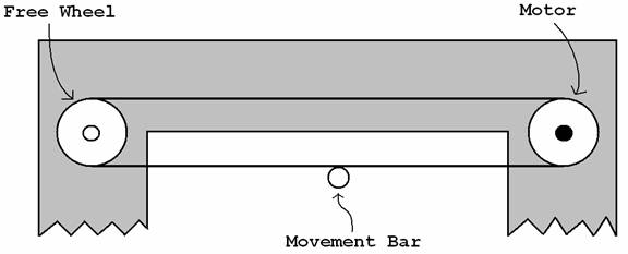
When the motor spins, the track is pulled left or right depending on the direction of rotation of the motor. The track revolves around the motor and a second point, a free wheel that is located at the other end of the board. Attached to the track is the movement bar. This same setup is attached to the other end of the movement bar on the other side of the board so that both ends of the bar in sync. Allowing both ends of the bar to move increases accuracy of the movement bars and reduces the load as each motor has less work to do. The only problem with this design was that if both motors did not operate together correctly, one end of the bar would be off target with respect to the other. This was not an issue, however, as we were able to find matching motors.
We originally had a separate unit attached to the rubber band track that held the movement bar in place. This additional metal block pulled the rubber band too much and added too much extra load to the motor. For these reasons, we decided to connect the movement bar directly to the rubber band.
Due to the tension in the rubber band, the metal that the motor and free wheel were attached to bent inward. This made the free wheel tilt inward as well. The main problem with this was that the rubber band got tangled in the bent wheel as it rotated, causing the motor to skip and stall. We had to use thicker metal and hot glue the free wheel anchor to the back.
The point at which the two movement bars intersect is the carriage unit. The carriage unit picks up the chess piece. A metal block with two perpendicular holes has a solenoid and electromagnet attached to the bottom. The perpendicular holes are for each movement bar. The solenoid lowers its core when no current is applied, allowing the electromagnet to make contact with the chess piece. When the current is applied to the electromagnet, the chess piece is attracted to it and sticks. The solenoid then turns on and pulls both up for movement.
The carriage unit:
Because the two perpendicular movement bars cannot intersect and touch, the holes for each through the carriage unit block cannot be on the same plane; one hole is slightly above the other. This would mean that one bar would be positioned lower than the other. Ideally, we should have simply lowered one set of movement rails to be in line with the lowered movement bar. Instead, we kept all the movement rails at the same height and the lower movement bar pulled down further on the rubber band track. The problem with this was that the lowered rubber band dropped too much and made the solenoid interfere with board pieces. To overcome yet another mechanical obstacle, we tried a multitude of ideas. We tried creating an additional layer above the droop height for the lower movement bar to rest on as it moved. This didn’t work due to friction between the layer and the movement bar. The idea which we settled with was using 2 rubber bands together to hold up the lower bar. This seemed to work very well as it did a good job of holding up the bar. The downside here was that the combined thickness of the rubber bands caused a problem in the wheels. The rubber bands would twist and make the motor skip and stall. We eventually were able to get around this be taping the rubber bands together so they would not twist.
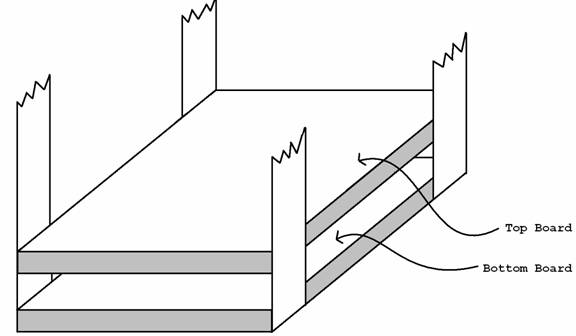
The actual chess board is a wood block. There are two boards with a gap in the middle for the control circuitry. The top block has the chess board while the bottom block has the circuitry. The figure below shows this setup. The movement rails are anchored to each block.
Control Circuitry:
Every signal from the microcontroller was optoisolated using a 4N35 IC. This is because every component used was some form of an inductor (motor, solenoid, electromagnet).
Motor Control:
We used four unipolar stepper motors, but ran them as bipolar motors. The reasoning behind this was that we had already sampled bipolar driver ICs (UC3770BN from TI). Each motor had two phases, so we needed two ICs per motor. Each IC had its own circuit driving it (The Motor Driver Circuit is included in the appendix). Since we were also using two motors per axis (two parallel movement rails), we hooked up two motors to each IC. The diagram below shows the break down of the microcontroller signals to each driver circuit. Note that although there is only one motor hooked up to each IC, there are in fact two in our circuit.
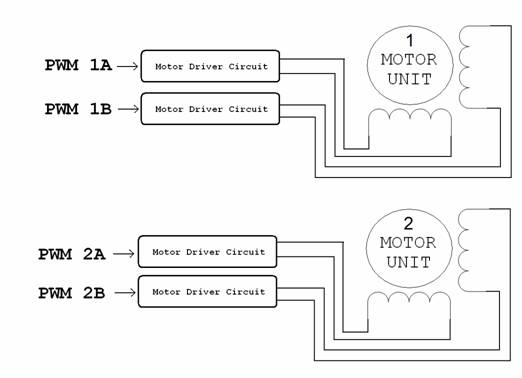
Although the stepper motors used were unipolar, we were able to run them as bipolar by ignoring the center tap. The MCU sends a PWM signal to each IC that alternates the current running through the coils. The phases of the two PWMs had to be properly aligned such that the proper sequence of switching occurred inside the motor to spin the magnet. The sequence for the two PWMs is shown below, one for each coil in the 2-phase motors:
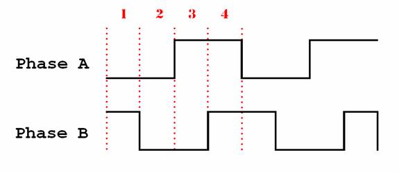
Instead of using the hardware PWMs available on the Mega32 chip, we created our own signal to control the proper sequence. We split the PWMs into a sequence of four steps that were cycled through on a timer. This allowed us to easily switch between forward and reverse driving of the motor by simply switching the PWMs to the motor. The length of each time slot (1,2,3,4) was chosen by observation. We added our load to the motor and determined a speed at which the motor would move fast, but not fast enough to not grab the rubber bands. A second constant was the step size. This determined how many rotations of the motor was in a single chess board tile. We calibrated this constant to fit our board size.
Solenoid/Electromagnet Control:
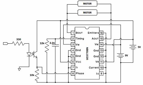
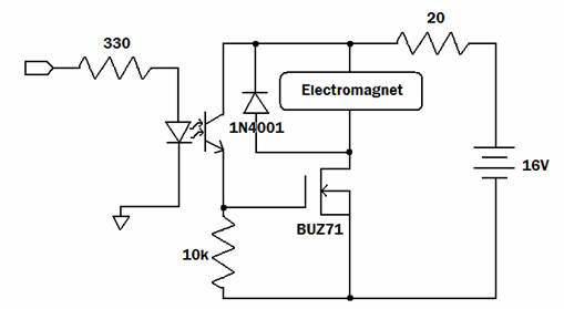
The control circuit for the solenoid and electromagnet were very similar. Both were based off the circuit used in the temperature controller lab (lab 5). An optoisolated signal goes to the gate of an NMOS transistor. A high signal allows current to flow through the transistor and through the component. The main issue in this circuitry was power. Both these components require a large amount of current to operate. The solenoid required about 0.4 Amps while the electromagnet required about 0.8 Amps. We placed a power resistor in series with each component to control current. Since each component was drawing power from the power supply in parallel, they didn’t affect each other as long as the power supple wasn’t current limited.
While we ordered the solenoid online, we built the electromagnet by hand. Our first attempt at the electromagnet was using an iron core and regular 24 gauge circuit wire. Not only was the wire hard to wind, but it was too thick to get many turns. We had to wrap enameled wire around the iron core. It took four layers separated by electrical tape to give us the field we needed to pick up the chess pieces.
Chess AI:
Board representation presented the first problem. The location of all the pieces must be stored in order to manipulate them in other functions. The board representation technique termed ‘0x88’ is the one we finally settled on. The structure is an array of 128 characters but only 64 of which are ever accessed. This allows you to use the upper 64 elements to store anything you wish. The advantage provided is that you can always tell when a position is still on the board by simply performing the operating (position&0x88) in c code. If the result is 0 then the position is a legal position. This simplifies many operations in the legal move generator. The board layout can be seen in the figure below:
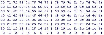
The actual legal board positions are on the left half of the diagram with the white rook being in the lower left hand corner. You can see that all of the hex values on the left half of the board will generate 0 when you do (position&0x88).
Move generation is one of the most important parts of chess. With just legal move generation you already have an AI that can “play” chess albeit very randomly. The problem with move generation on the Mega32 is the limited SRAM size. Every legal move generated takes up 2 bytes and every board position has about 40 legal moves associated with it. Also every recursive call associated with the alpha-beta pruning algorithm will need to generate its own set of legal moves. That means that after only five recursive calls we’d have already used 400 bytes of SRAM. What we did instead was generate legal moves on the fly. Every time the alpha-beta pruning algorithm needs a new legal move it goes through the entire board in order to find the nth legal move. So when it needs move 1 it calls findMove(1) and the function findMove will go through the board array and find the first legal move. If findMove(30) is called, it will keep going through the function finding legal moves until it finds the 30th legal move and return that to the alpha-beta pruning algorithm. This results in only the 2 bytes needed to store a single move in memory but the tradeoff is that it is more and more computationally expensive to call findMove(n) for large values of n.
The brains of the chess program are really in the alpha-beta pruning algorithm. This algorithm is an extension of the mini-max algorithm. The pure mini-max algorithm is a recursive algorithm which evaluates all of the children nodes of the search tree. Then the algorithm picks the move that would maximize the minimum value of the opponent’s move. So it is essentially picking the best move assuming that the opponent will also attempt to maximize its own position.
The advantage that alpha-beta pruning has is its ability to reduce the search tree. Mini-max has a typical branching factor of 40 for chess which can be reduced by a factor of two using alpha-beta pruning. The alpha-beta pruning algorithm accomplishes this feat by maintaining two new values called alpha and beta. Alpha represents the minimum value the maximizing player (the computer in our case) is guaranteed while beta represents the maximum value the minimizing player (the human) is guaranteed. Alpha and beta are initially set to INT_MIN, which represents a terrible score which the computer hopes to improve as it finds better moves, and INT_MAX, a score the computer hopes it can refute with better moves. With these values, it can eliminate large portions of the search tree any time that it produces an alpha or beta cutoff. An alpha cutoff means that the current move being searched will not be better than a move it has already seen and thus won’t need to be searched. A beta cutoff means that the move being searched can be refuted by the opponent and so is also not necessary to search. These two factors have no effect on what the best move ends up being but drastically improve the search speed.
The other half of chess is the human moves. This is done by just using a receive ISR as we did in lab 3. The notation to enter is called algebraic chess notation. A diagram of the board is shown below:

(from http://en.wikipedia.org/wiki/Algebraic_chess_notation)
The move is entered in the format “fromto” so that entering “e2e4” corresponds to moving the white pawn on rank 2 to rank 4.
Our project did not accomplish all the goals we set. The microcontroller was able to play chess, but it was not able to effectively move a chess piece. The problem came in the accuracy of the stepper motors. While we were able to consistently move the carriage unit to the same location, we were not able to move it to multiple locations consistently. For example, we were able to calibrate the motors to move a single piece, but the other pieces could not be moved accurately. Stepper motors are ‘digital’ motors, so this kind of inaccuracy was surprising. We initially thought it had something to do with the friction to start the motor moving, so we split up multiple step movements into a series of single steps. This did not work. We think it has to do with the movement rails not allowing enough freedom to the movement bars. The movement bars that are positioned lower are attached with two rubber bands that cause an occasional skip.
The carriage unit itself worked very well. The solenoid turned on and off on command and the electromagnet did the same. The electromagnet had no problem attracting the small washers we used as chess pieces. Both drew about 1.2 Amps combined from the 16V rail.
The control circuits themselves worked as intended. The power resistors did get quite hot, but they were able to handle the load.
Consumer Safety:
Because the user is not able to interact with the actual chess board during the game, the concerns over the safety of the user are limited to the serial port. The user would be just as safe as if he or she were surfing the internet. However, because not all users are intelligent, there is a possibility that the user might interfere with the chess board. The solenoid and electromagnet get quite hot, so we used thermal paste to attach them to the carriage unit block. The metal block then acts as a heat sink to help cool those components. Another concern is the sharp metal edges. The edges were filed down, but they are still not perfectly smooth. Tape was placed around the sharp areas to minimize damage.
Another important concern is messy wiring. This is not only tough to debug, but could also lead to unexpected shorts. We neatly wound all wire and taped together bundles. Loose wiring was taped to edges and into the protoboards.
Our final design went through many iterations before it became the final design. We initially set out to create a linear stepper motor of our own using electromagnets, but that idea was quickly abandoned due to cost. The next greatest challenge we had was using the stepper motors in lab to create linear motion. We finally chose a design that we though would work, but there were many mechanical problems that were not foreseen.
The overall design worked very well. The only problem would be the inconsistent movement due to the rubber bands getting occasionally caught on the wheels. The solenoid and electromagnet worked very well, but got too hot. The solenoid got hot enough to melt the hot glue attaching it to the carriage unit. This was fortunately only a problem when running the solenoid for extending periods of time, something we didn’t do.
If we were to do this project again, the biggest issue to correct would be the accuracy of the movement rails. If we had additional time, we could have used position sensors to control the duration of the motors rather than using a predetermined calibration constant. Had we come up with a better design for the movement rails, it may not have been necessary altogether. We should also create better power management to properly control current to all parts of the design. The power management we have right now is very basic but meets our requirements. We should also create a better user interface than HyperTrm.
Although we did use someone else’s design for the stepper motor driver, we had to change parts of it to match our needs. The borrowed design also used a different variation of the chip we had. However, the design was an excellent resource that taught us a lot about stepper motor ICs in general.
IEEE Code of Ethics:
During the course of our project, we adhered to the IEEE code of ethics. Our project did not work exactly to the specifications we intended, and we made note of that in our report. We could have easily tried to cover up our mistakes, but instead we were honest about them. We also made note of the fact that parts of our project became quite hot. This course of action will prevent injury to those who would otherwise not know the dangers of high current. The neat wiring is also a safety measure intended to reduce the chance of a stray wire making a dangerous connection.
For many of our problems we sought outside help. If we solved our problems through a solution presented by others, we made mention of their contribution to our design. We treated everyone we came into contact with as an equal collegue. Almost everyone we asked offered valuable tips, and we did the same whenever possible. Never did we try to sabotauge another group's project in an attempt to boost ours.
Cost was a major concern for our project. We needed many mechanical parts that took a big part of our budget. Every part we used is listed in the parts list below. Rather than try to stay under budget by falsifying information, we tried to minimize cost by selecting alternate methods. Our original idea of creating a linear stepper motor was a casualty of cost.
|
|
|
|
|
|
|
|
|
|
|
|
|
|
|
|
|
|
|
|
A fully commented version of the code can be found here.
Parts List:
|
Part |
Vendor |
Quantity |
Unit Price |
Price |
|
Stepper Motors |
ECE 476 Lab |
4 |
$1.00 |
$4.00 |
|
Mega32 Microcontroller |
ECE 476 Lab |
1 |
$8.00 |
$8.00 |
|
Power Supply |
ECE 476 Lab |
2 |
$5.00 |
$10.00 |
|
4N35 Optoisolater |
ECE 476 Lab |
6 |
$0.00 |
$0.00 |
|
BUZ71 |
ECE 476 Lab |
2 |
$0.00 |
$0.00 |
|
1N4001 Diode |
ECE 476 Lab |
2 |
$0.00 |
$0.00 |
|
Protoboard |
ECE 476 Lab |
1 |
$5.00 |
$5.00 |
|
Enameled Wire |
ECE 476 Lab |
1 |
$0.00 |
$0.00 |
|
RS232 Connector |
ECE 476 Lab |
1 |
$1.00 |
$1.00 |
|
Wood Base |
Home Depot |
1 |
$3.00 |
$3.00 |
|
Nuts and Bolts |
Home Depot |
1 |
$0.99 |
$0.99 |
|
Wheels (Movement Rails) |
Home Depot |
4 |
$3.00 |
$12.00 |
|
Washers (Chess Pieces) |
Home Depot |
1 |
$1.00 |
$1.00 |
|
Solenoid |
Jameco |
1 |
$7.45 |
$7.45 |
|
MAX233 RS232 Driver |
Maxim-IC |
1 |
$0.00 |
$0.00 |
|
Metal |
Scraps |
1 |
$0.00 |
$0.00 |
|
UC3770BN Stepper Motor Driver |
Texas Instrument |
4 |
$0.00 |
$0.00 |
|
|
|
|
Total: |
$52.44 |
Task Breakdown:
Usuf –
Frank –
References:
Our stepper motor driver circuits were borrowed and adapted for our needs from another project. The project is at RIT, Capability Enhancements for Autonomous Mobile Wireless Sensors. They used the UC3770AN IC to control stepper motors than controlled wheels on a car. Their paper can be found here.
The datasheet for the UC3770BN stepper motor driver can be found here.
Our solenoid and electromagnet driver circuits were borrowed from the design used in a previous 476 lab, the temperature controller lab (lab 5).
http://www.cis.uab.edu/hyatt/boardrep.html - Board representation examples and structure of a chess program.
http://www.fierz.ch/strategy1.htm#generator – Explanation of all the functions that would be needed to write a 2-person game of pure strategy. Also explained all the different variations of the mini-max algorithm.
http://www.ics.uci.edu/~eppstein/180a/970417.html - More pseudo-code for the different search algorithm.
http://www.cs.wisc.edu/~mjr/Pente/ - Very detailed explanation of the mini-max and alpha-beta pruning algorithms.
Circuit Diagrams:
Stepper Motor Driver Circuit (x4):
Solenoid Driver Circuit:

Electromagnet Driver Circuit:
Mechanical Drawings: