ECE 476 Final Project: Intelligent Multimedia System
Ah Yud Chan (ac348), Wing Mau Cheung (wc267), and Sheng-Yi Shih (ss555)
|
|
||
| Ah Yud Chan (ac348) | Wing Mau Cheung (wc267) | Sheng-Yi Shih (ss555) |
|
|
||
| Ah Yud Chan (ac348) | Wing Mau Cheung (wc267) | Sheng-Yi Shih (ss555) |
 |
 |
| You can't Beat this Music |
This project implements a multi-function multimedia system that allows the user to sing with the music video and generate some fancy sound effects.
In recent decades, multimedia becomes quite popular in our daily life. In fact, multimedia system has existed for a long time. People enjoy the time viewing photos, listening to music, and watching movies. With the development of technology, we are able to create, modify and edit multimedia data. Also, thanks to the emergence of the digital era, we have more tools that help us to achieve these goals. For example, we could store the analog data in digital format to make it more robust and lasting. Besides, we are able to synthesize the data and generate some amazing effects.
Our final project is to design an intelligent multimedia system. This system allows users to use the microphone as the analog input to speak and sing. Besides, since it is not only a multimedia system but an “intelligent” multimedia system, we have implemented several features that help the users to modify, synthesize, and create a multimedia record. For example, we could adjust the volume of the voice and music. Besides, we could generate the echo of our voice as if we are in a theatre. Furthermore, since we could transform the analog signal into digital format, we are able to manipulate the audio data. In this project, we used several popular mathematical models in the field of Audio Signal Processing that help us to simulate specific sound effects. All the audio data could be recorded in real time by passing to the PC via the RS232 COM Port.
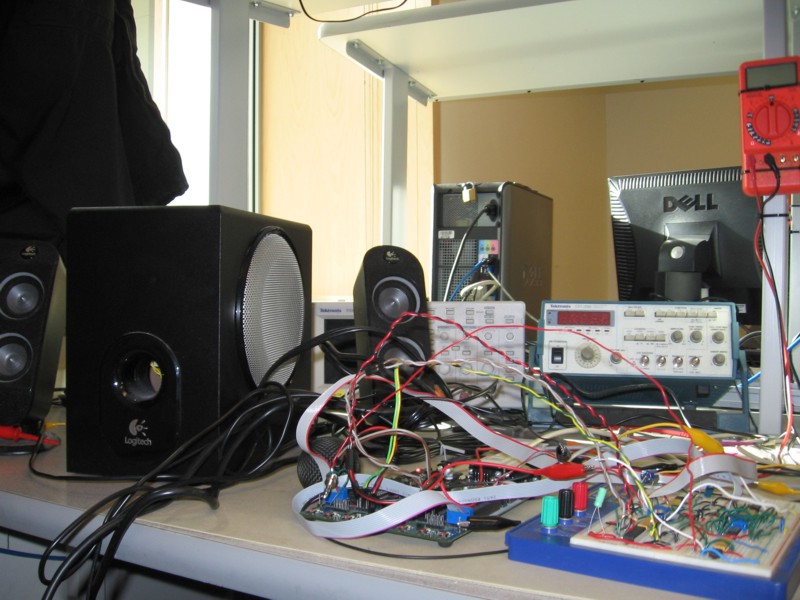
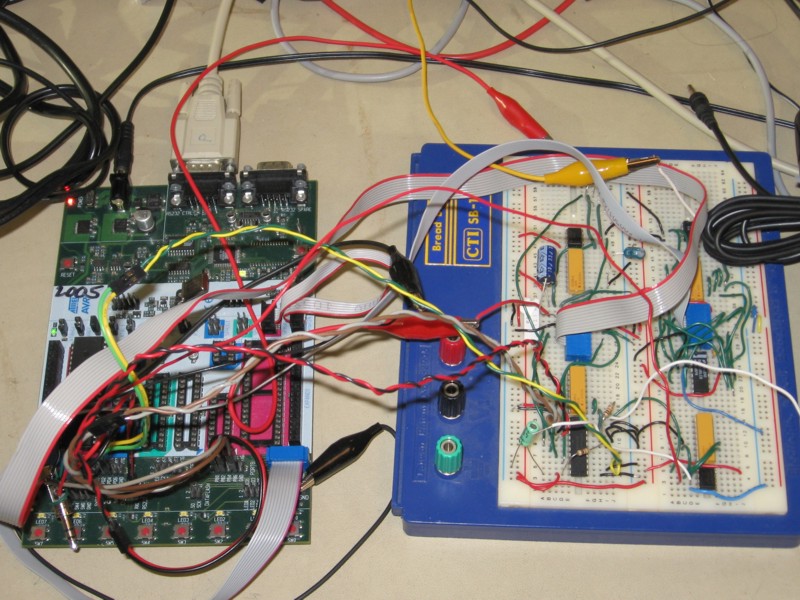
The kernel of the system is controlled by the ATMega32 microcontroller, same as the one we used in the regular lab sections. The voice signal input is generated from the microphone, and the music signal is generated from any music application such as a MP3 player or PC. We passed both of the audio signals through a pre-amplifier to boost its signal strength. Then, we used an analog-to-digital converter chip (ADC0801) to transform the analog signal into digital data. The digital data can then be propagated to the microcontroller. Besides, we use the RS232 serial port to communicate between the microcontroller and the PC. This design allows us to transfer the music data to the PC from this multimedia system in real time. In the microcontroller, we could capture both of the voice signal and music signal and mix them to generate special effects. The output signal can then be propagated to a digital-to-analog chip (DAC0808) to transform the digital data to analog signal. Finally, the signal will be passed to the speaker and generate a wonderful melody. In order to provide user with a friendly graphic user interface (GUI), we integrate the technology of JAVA and Visual C++ in Windows programming. User could apply the featured effects to the voice signal via this GUI.
The final project is a good experience for us to integrate all the knowledge that we gained in this course and some other related courses. We chose this topic because we are all interested in multimedia signal processing. Also, we thought that this topic would be a good chance for us to combine our knowledge in various fields. For example, we applied the knowledge that we gained in this course to process the voice and music signal utilizing the optimal capacity of all the components to generate the amazing effects. Also, we could understand more about the analog circuit when we integrated all the hardware components. Furthermore, we had integrated various programming languages such as C, C++ in Windows programming, and Java into our multimedia system. During the process of development, we overcame the challenge of incompatibility between C++ and JAVA. Finally, to process the audio signal, we did some research in the field of Digital Signal Processing and combined some mathematical models to generate proper effects that we applied in this project.
The overall design block of this system is shows as follows. In this project , we used two different channels for our audio signal inputs: one is a microphone and the other is a music application such as MP3 player or PC. Initially both of the signals are in analog format, so we needed two analog-to-digital converters to transform the analog signal into digital format before feeding into the microcontroller. Since there is only one analog-to-digital converter embedded in ATMega32, we used the internal analog-to-digital converter for the voice channel and an external analog-to-digital converter chip (ADC0801) for the music channel. The signal could be manipulated in the microcontroller. The signal will be propagated to the digital-to-analog converter chip (DAC0808) to be transferred into analog format. Finally, the processed signal is passed to a speaker to generate the sound. In this project, we use the GUI in Windows XP as our system control. It provides a user-friendly graphical interface to allow the users to control the system by a mouse click. The mouse click is then turned into a command to the microcontroller via the COM Port.
There were so some minor changes we made in the system architecture while we were working on this project. Some of the changes were made since we encountered some limitation in the hardware. For example, in a common karaoke system, we need at least two channels for one voice input and one music input. However, there is only one internal analog-to-digital converter in ATMega32. If we use it for both voice and music signals alternatively, the sample rate will be reduced to less than half of the original one. This would lower the sound quality. In order to solve this problem, we decided to use an external analog-to-digital converter chip (ADC0801) for the music channel. In this way, the microcontroller can sample both the voice and music signals in 8KHz in maximum concurrently which the produces a higher sound quality. Besides, initially we decided to output the processed signal to the speaker in the same approach that we learned in Lab 2. However, we found that the sound quality was pretty bad since this approach used PWM mode of the microcontroller to generate an approximate signal and hence the accuracy of signal output was lowered. To cope with this problem, we used a digital-to-analog chip (DAC0808) to transform the digital output to an analog output that makes the sound more dulcet. For the choice of user interface, we initially decided to use the buttons on the STK-500 board as the control panel. However, we found that using a PC can provide a much flexible and user-friendly control interface. Hence, we decided to use a GUI running on the PC as the software control panel. All the changes we made help improving the performance of the multimedia system on the whole.
Since all of our team members are ECE MEng students, Cornell University owns all copyrights and potential, patents related to this project. Since the ideas and implementation of our project hardware are solely our own, there should not be any trademark, patent, or copyright infringement issues.
Figure 1. Hardware Design Block
Embedded System Side
In our multimedia system, we used UART of RS232 standard to receive command from PC and send mixed signal output back to PC. Also we used the timers to control the sampling frequency of voice and music signals as well as mixed signal output.
Features/effects supported by the microcontroller firmware
|
Features/Effects |
Description |
Implementation Concept |
|
No Effect |
The multimedia system simply outputs the mixed signals |
The mixed signal is the combination of the voice signal and the music signal |
|
Frequency Control |
Users can choose within the range of 1 ~ 8 KHz as the sampling frequency where 8KHz is of best quality |
The sampling frequency is controlled by the timer interrupt of the microcontroller |
|
Volume Control |
Users can adjust volume of voice and music signals within the range of 0 ~ 10 scale where 10 is of highest volume |
The voice and music signals are scaled according to the selected scale before combination |
|
Echo |
Users can select echo effect within the range of 1 ~ 15 scale where 15 is of most noticeable echo effect |
The voice output is the combination of 75% of current voice signal and 25% of previous voice signal |
|
Distortion - Patient |
Voice output sounds like a patient speaking softly |
The high magnitude of voice input signal is filtered and replaced by the upper bound and lower bound |
|
Distortion - Walki-Talki |
Voice output sounds like speaking through a walki-talki with distortion |
The voice output signal is the square of the voice input signal |
|
Distortion - Robot |
Voice output sounds like a robot voice |
A high frequency sine wave signal is added to the voice signal |
|
Distortion - Gaussian Noise |
Voice output consists of additive white Gaussian noise |
A random signal is added to the voice signal |
|
Distortion - Lower Pitch |
Voice output sounds like lowering the pitch a bit |
The voice output signal is generated by averaging 16 previous voice input signals |
Recorded effect samples: Echo 1KHz 4KHz 8KHz Patient Walki-Talki Robot Gaussian Noise Lower Pitch
PC Software
In order to facilitate the communication between a PC and the microcontroller, we make use of the high speed serial port. The console program configures the COM Port to run at a baud rate of 115.2kbps. The program gets the command from the graphical user interface and transmits it to the microcontroller, and at the same time receives the real time digital audio data from the microcontroller. The Java application on top of the console program is to provide graphical user interface for the multimedia system and the useful operations such as displaying the voice waveform, recording the voice in a wave file and sending an email attached with the wave file. The following diagram demonstrates the general data flow between the microcontroller, the console program and the Java application.
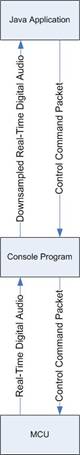
Figure 2. The dataflow between the microcontroller, the console program and the Java application
The following is the user interface of our program. The left panel is to display the waveform of the audio signal. The right panel is effect control and volume control panel. All the buttons on the bottom are to control the operations of the multimedia system.
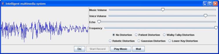
Figure 3. PC Graphical User Interface
UART
In our multimedia system, we implemented a Graphical User Interface written in Java running on the PC to control the whole embedded system. The UART Receive Complete Interrupt is enabled to allow the program jump to the interrupt service routine to receive the command packets. The received data is then passed to processCommandPacket() to be saved into the command packet buffer. A state machine is implemented in the packet reception. The code is as follows.
//UART RX Complete ISR
interrupt [USART_RXC] void uart_receive(void)
begin
//Process the char received from serial port
processCommandPacket(UDR);
end
//Process command packet received from serial port
void processCommandPacket(unsigned char data)
begin
switch (commandState)
begin
case CMD_B1:
//First byte of command
commandPacket.command = data;
//Change command state
commandState = CMD_B2;
break;
case CMD_B2:
//Second byte of command
commandPacket.command |= (((unsigned int)data)<<8);
//Change command state
commandState = LEN_B1;
break;
case LEN_B1:
//First byte of packet length
commandPacket.dataLen = data;
//Change command state
commandState = LEN_B2;
break;
case LEN_B2:
//Second byte of packet length
commandPacket.dataLen |= (((unsigned int)data)<<8);
//Change command state
commandState = DATA_SEC;
//Disable RX complete interrupt
UCSRB.7 = 0;
break;
end
end
There are 7 different commands the PC can send to the microcontroller. They are listed as below.
//enum for commands
typedef enum {
TURN_ON,
TURN_OFF,
SET_ECHO,
SET_MUSIC_VOLUME,
SET_VOICE_VOLUME,
SET_SAMPLE_FREQUENCY,
SET_DISTORTION
} Command;
The packet structure for command packet
has 4 bytes. The first 2 bytes are for 16 bits command. The second 2 bytes are
for 16 bits payload length of the command packet. The command packet is stored
to the variable commandPacket and processed by the checkCommand()
function later. The checkCommand() function handles the command packet sent from
the PC software. The code is shown as follows.
//enum for command state
typedef enum {
CMD_B1,
CMD_B2,
LEN_B1,
LEN_B2,
DATA_SEC
} CommandState;
//Command packet structure
typedef struct CommandPacketTag {
Command command;
unsigned int dataLen;
} CommandPacket;
//Check the command and execute it
void checkCommand()
begin
switch (commandPacket.command)
begin
//Turn on the multimedia system
case TURN_ON:
turnOn();
commandState=CMD_B1;
break;k;
//turn off the multimedia system
case TURN_OFF:
turnOff();
commandState=CMD_B1;
break;
//Set the music volume
case SET_MUSIC_VOLUME:
setMusicVolume();
commandState=CMD_B1;
break;
//Set the voice volume
case SET_VOICE_VOLUME:
setVoiceVolume();
commandState=CMD_B1;
break;
//Set the sampling frequency
case SET_SAMPLE_FREQUENCY:
setSampleFrequency();
commandState=CMD_B1;
break;
//Perform the echo effect
case SET_ECHO:
setEcho();
commandState=CMD_B1;
break;
//Set distortion effect
case SET_DISTORTION:
setDistortion();
commandState=CMD_B1;
break;
end
//Enable serial communication receive interrupt
UCSRB.7=1;
End
The sampled audio signal is sent to the PC in the timer interrupt. The code is as follows.
//Send the mixed signal to PC via the serial port
while (!(UCSRA & (1<<5)));
UDR = mixedSignal;
Signal Sample Buffer
In the multimedia system, we have designed some special effects for voice processing. Therefore we implemented a sample buffer of size 1500 bytes to store the signal samples and reuse the buffer continuously. The implementation is as follows.
//Number of byte in SRAM used for sample buffer
#define SAMPLE_BUFFER_SIZE 1500
unsigned char sample[SAMPLE_BUFFER_SIZE]; //Sample data array
Internal ADC
Our program used the internal Analog-to-Digital Converter of ATMega32 microcontroller to obtain the voice signal from a microphone via an Op-Amp circuit to amplify the signal strength. The conversion rate is up to 15,000 samples at maximum per second. Our system’s sampling rate is 8000 Hz. So the internal ADC suits for our system requirement. The reference voltage is 5V. The Op-Amp circuit has a 2.5V DC-offset. Therefore, for no signal, the digital representation is theoretically 128. But in our tests, we found that the sample data of the voice signal was in fact 120. This is because the DC-offset is not exactly 2.5V and the circuit is imperfect due to interference and impedance.
In the function processSignal(), the following code is to get the voice signal from ADC, store the signal to a sample buffer and then start another conversion.
//Get the voice signal from the ATMega32's on-chip ADC
voiceSignal = ADCH;
//Store the voice signal in the sample buffer
sample[sampleIndex] = voiceSignal;
//Start another voice ADC conversion
ADMUX = 0b11100000;
ADCSR.6=1;
External ADC
Since the ATMega32’s internal ADC is used to sample voice signal, it is not capable to sample both voice and music signal at the same time at 8KHz. Therefore we used an external ADC chip ADC0801 to sample the music signal. Pin 0-3 of PortB and pin 4-7 of PortA are connected to the data port of ADC0801 to get the digital data. Pin 4 of PortD is used to control the WR pin of ADC0801 in order to command it to start another conversion by setting it to be 0 and then 1 immediately. The code is as follows.
//Get the music signal from the external ADC
musicSignal = ((PINB & 0xf)<<4)+(PINA>>4);
//Start another music ADC conversion
PORTD.4 = 0;
PORTD.4 = 1;
External DAC
The mixed signal of voice and music signals is eventually output to PortC for digital-to-analog conversion using DAC0808 chip and the analog output of DAC0808 is connected to a speaker to output the signal.
//Output mixed signal to speaker
PORTC = mixedSignal;
Timer0
The sampling rate of both voice and music is controlled by
Timer0. TCCR0 is set to be 0x0b which means Clear Timer on Compare Match mode is
chosen and Timer0 is prescaled down to 8 times. OCR0 is set to be
![]() which
means the Timer0 compare interrupt frequency is
which
means the Timer0 compare interrupt frequency is![]() .
When there is a Timer0 compare interrupt, the function processSignal() is
invoked to get the voice and music samples and do the selected effects. The code
is as follows.
.
When there is a Timer0 compare interrupt, the function processSignal() is
invoked to get the voice and music samples and do the selected effects. The code
is as follows.
//Reset Timer0 to change sampling rate
TCCR0 = 0x0b;
OCR0 = 250 / sampleScale - 1;
Timer1
We used an external ADC chip (ADC0801) for sampling the signal
data of music. Since ADC0801 needs a clock, we allocated the pin OCR1A of Timer1
to drive its clock so that we can make sure ADC0801 is synchronized with
ATMega32. COM1A1 is set to be 0 and COM1A0 is set to be 1 that the pin OC1A is
cleared whenever OCR1A matches Timer1. Timer1 is assigned with prescaler 8. The
clock signal is equal to
![]() .
When the ADC0801 is running at 1MHz, its ADC conversion time is 73 microsecond.
Therefore, its maximum working frequency is 1/73microsecond = 13698Hz, which is
larger than 8000Hz we required.
.
When the ADC0801 is running at 1MHz, its ADC conversion time is 73 microsecond.
Therefore, its maximum working frequency is 1/73microsecond = 13698Hz, which is
larger than 8000Hz we required.
//Enable Timer1 to output a clock to synchronize the external ADC chip
TCNT1 = 0;
TCCR1A = 0b01000000;
TCCR1B = 0b01001010;
OCR1A = 0;
Basic Features
Varying sampling frequency
The multimedia system allows the users to select preferred sampling frequency for compare and contrast purpose. Lower sampling frequency can also be chosen to lower sample size and hence reduce the storage of the recorded data in the PC. Whenever the system receives a command packet from the PC which indicates to set the sampling frequency, the function setSampleFrequency() is invoked to handle the rest of the packet payload. The code is as follows.
//Set the sampling frequency
case SET_SAMPLE_FREQUENCY:
setSampleFrequency();
In the function setSampleFrequency(), the payload of the command packet indicates the sampling frequency chosen by the user through the GUI in the PC. Our multimedia system is set to receive an integer ranging from 1 to 8 in which the integer means the sampling frequency in KHz. The code is as follows.
//Read serial data(sampling rate in KHz)
sampleScale = (unsigned char)UDR;
//Reset Timer0 to change sampling rate
TCCR0 = 0x0b;
OCR0 = 250 / sampleScale - 1;
Adjusting voice volume
Our multimedia system allows the users to adjust the volume of voice through the GUI in the PC. The scale is from 1 to 10 by which 1 means lowest and 10 means highest. Whenever the system receives a command packet from the PC which indicates to set the voice volume, the function setVoiceVolume() is invoked to handle the rest of the packet payload. The code is as follows.
//Set the voice volume
case SET_VOICE_VOLUME:
setVoiceVolume();
In the function setVoiceVolume(), the payload of the command packet indicates the voice volume scale, voiceScale, is chosen by the user through the GUI in the PC. The code is as follows.
//Read serial data(voice volume scale)
voiceScale = (unsigned char)UDR;
Then the actual voice volume is adjusted by scaling up the voice signal according to voiceScale with MAX_VOLUME_SCALE as the base. The code is as follows.
//Set volume of voice signal
voiceSignal = (unsigned char)(((int)(voiceSignal) - 120)* voiceScale / MAX_VOLUME_SCALE + 120);
Adjusting music volume
The multimedia system also allows the users to adjust the volume of music through the GUI in the PC. The scale is from 1 to 10 by which 1 means lowest and 10 means highest. Whenever the system receives a command packet from the PC which indicates to set the music volume, the function setMusicVolume() is invoked to handle the rest of the packet payload. The code is as follows.
//Set the music volume
case SET_MUSIC_VOLUME:
setMusicVolume();
In the function setMusicVolume(), the payload of the command packet indicates the music volume chosen by the user through the GUI in the PC. The code is as follows.
//Read serial data(music volume scale)
musicScale = (unsigned char)UDR;
Then the actual music volume is adjusted by scaling up the music signal according to musicScale with MAX_VOLUME_SCALE as the base. The code is as follows.
//Set volume of music signal
musicSignal = (unsigned char)(((int)(musicSignal) - 120)* musicScale / MAX_VOLUME_SCALE + 120);
Special Effects
In our system, we have implemented 2 main effects to the voice signal: echo and distortion. These effects are done by manipulating the amplitude of the voice signal in different ways.
1. Echo
Whenever the system receives a command packet from the PC which indicates to set the echo effect, the function setEcho() is invoked to handle the rest of the packet payload. The code is as follows.
//Perform the echo effect
case SET_ECHO:
setEcho();
In the function setEcho(), the payload of the command packet indicates the echo delay chosen by the user through the GUI in the PC. The echo delay is between 0 and 1500 samples which are stored in the sample buffer. The greater the echo delay, the more noticeable is the echo effect. The code is as follows.
//Read serial data(echo delay range)
x = (int)UDR;
if(x == 0)
effect=NO;
else
begin
effect = ECHO;
echoDelay = (x)*100;
end
2. Distortion
In our system, there are totally 5 distortion options that a user can choose from. The distortion options are Patient, Walki-Talki, Robot, Gaussian Noise and Lower Pitch. Whenever the system receives a command packet from the PC which indicates to set the distortion effect with patient as the option, the function setDistortion() is invoked to handle the rest of the packet payload. The code is as follows.
//Set distortion effect
case SET_DISTORTION:
setDistortion();
In the function setDistortion(), the payload of the command packet indicates the distortion option chosen by the user through the GUI in the PC. The code is as follows.
//Read serial data(distortion option)
x = (int)UDR;
//Set distortion effect and distortion option
if(x==0)
effect = NO;
else
begin
effect = DISTORTION;
distortionOption = (unsigned char)x;
end
2.1 Patient effect
The Patient distortion option is done by filtering the high
volume voice signals. In this way, the voice will sound like a patient speaking
very softly. From the result of our tests, we designed the multimedia system to
only allow signal magnitude within ![]() 10
of 120 as the DC offset. Therefore, we chose 130 as the upper bound and 110 as
the lower bound of the filter. The code below is in charge of
applying this effect to the voice signal.
10
of 120 as the DC offset. Therefore, we chose 130 as the upper bound and 110 as
the lower bound of the filter. The code below is in charge of
applying this effect to the voice signal.
//Filter high and low voice signals
if(voiceSignal>130)
voiceSignal=130;
else if(voiceSignal<110)
voiceSignal=110;
2.2 Walki-Talki effect
The Walki-Talki distortion option is done by distorting the voice signals to its square from the result of our tests. In this way, the voice will sound like the actual voice processed by a walki-talki. The code below is in charge of applying this effect to the voice signal.
//Change the voice signal to exponential of itself
voiceSignal = (unsigned char)((((int)(voiceSignal) - 120)*((int)(voiceSignal) - 120)) + 120);
2.3 Robot effect
The Robot distortion option is done by adding a sine wave signal to the voice signals from the result of our tests. In this way, the voice will sound like a robot. The code below is in charge of applying this effect to the voice signal. Setting the upper threshold and lower threshold to the voice signal can filter the noise generated by the sine wave when there is no voice signal.
//Add a sine wave signal to the voice signal if there is voice
if(voiceSignal>UPPER_THRESHOLD || voiceSignal<LOWER_THRESHOLD)
voiceSignal = (unsigned char)((((int)(voiceSignal) - 120)+ (sineTable[i]>>1)) + 120);
2.4 Gaussian Noise effect
The Gaussian Noise distortion option is done by adding a random signal to the voice signals. In this way, the voice will sound like having a background noise (Additive White Gaussian Noise). The code below is in charge of applying this effect to the voice signal. The random number generated by the function rand() is of 16 bits that we decided to use its 7 most significant bits as the random signal.
//Apply an additive white Gaussian noise to the voice signal
voiceSignal = (unsigned char)((int)(voiceSignal)+ (rand()>>9));
2.5 Lower Pitch effect
The Lower Pitch distortion option is done by averaging the past 16 voice signals from our test. In this way, the high frequency glitches are filtered and the voice will sound like in a lower pitch. The code below is in charge of applying this effect to the voice signal.
x = 0;
//Add up previous 16 voice samples
for(i=0; i<16; i++)
x += (int)sample[sampleIndex - i];
//Get the average of the samples
x >>= 4;
//Increase voice signal twice to enhance noticing the difference
voiceSignal = (unsigned char) (x);
Software Design - PC Software
The console program is written in Visual C++. It relies on the Platform SDK system APIs to access the serial port, to generate the portable “.wav” file, and to access the basic system resource. It can be run under command prompt, but we created a Java application to make use of this program more user-friendly. The communication between the console program and the Java application is based on a standard input pipe and a standard output pipe.
Console Program
The console program consists of two threads such as a main thread and a background thread. The main thread is to initialize the program variables, to initialize the serial port, to create a background thread, and to handle the user command from the Java application. The background thread is to receive the incoming real-time digital audio data from the microcontroller via the serial port. The timeout configuration for the serial port is set to infinity, so that the receive command of the serial port only returns when there is data received from the microcontroller. Once the data is available, the thread appends the audio data into the wave file if it is required. Moreover, the thread stores the data into an array buffer until one second is elapsed. Then, the thread down-samples the audio data and extract only 80 samples and sends the data to the GUI to display.
The standard input pipe operates in the blocking mode. Every time, the program reads an input from the pipe. It will be blocked in the call. Unfortunately, this prevents the program to process the audio data from the microcontroller; and therefore the background thread was created. Since two threads run concurrently and share the same resources in the program, we need to maintain the consistency and integrity of the data in the program. We uses the method of mutual exclusion. We create a critical section object. If a thread attempts to use the sharing resources, it first acquires the critical section object. If the object has been acquired by another thread, it waits until the object is released form another thread.
The program consists of a state machine and it consists of three states: IDLE_STATE, ON_STATE, and NORMAL_REC_STATE. The state machine determines what is going to do in the background thread. In the IDLE_STATE, the thread does nothing and is put in the sleep mode every second. So, the thread does not keep running in the while loop and consume all the CPU time of the PC. In the ON_STATE, it waits for the incoming audio data from the microcontroller and sends the data to the Java application. In the NORMAL_REC_STATE, it also appends the audio data into the wave file.
We used the sample code from the Microsoft Platform SDK for Windows Server 2003 R2 package. The code is stored in the dxutil.h, dxutil.cpp, dsutil.h, and dsutil.cpp files. They can be found under the following directory of the package:
“\Samples\Multimedia\DirectShow\DMO\DMODemo”
The sample code consists of a CWaveFile class. This class provides the methods to create an audio file in Windows, “.wav” format. Our program sends the digital audio configuration to the “Open” method in the class and creates a zero-length audio file. The configuration consists of the sampling rate, the bits per sample, and the number of channels of the audio source. It calls “Write” method to append audio data to the file every time it receives data from the microcontroller. At last, it calls “Close” method to close the file when the program finishes recording.
Java Application
The Java application consists of various buttons to allow users to control the intelligent multimedia system. When a user launches the application, he needs to press “On” button to start sampling the audio signal in the microcontroller. The audio signal will be shown on the wave display panel, and the panel is updated by a software timer every 1 second. The “Start Record” button will become enabled. He can press the button and starts recording the audio signal in a wave file. A file chooser dialog pops up to select the file name. If he wants to play a karoke clip, he can press “Play Music” and select the karoke clip to be played. If he wants to stop recording, he can press the “Stop Record” and press the “Mail” button to send out the wave file to his friends or himself. Another dialog box will pop up to input the wave file to be sent, the user account and password of the sender of the email, the recipient email address, and the message content of the email. If he finishes using the multimedia system, he can press the “Off” button to turn off the microcontroller system. After he presses the button, the “Start Record” button becomes disabled.
The Java application consists of radio buttons and sliders to control the voice and music quality of the intelligent multimedia system. The radio buttons selects the kind of distortion, including Patient, Walki-Talki, Robot, Gaussian Noise, and Lower Pitch, to be applied to the voice of the singer. The sliders are to configure how great the scales can be for the music and voice volumes, how much delay is preferred for the echo, and what is the sampling rate of the audio signals. The ranges of music and voice volumes are 0 to 10. The range of the echo is 0 to 15. A zero value means no echo. The frequency value ranges from 1KHz to 8KHz, and it is in step of 1KHz. This slider is disabled when the system is on. This limitation is to simplify our buffering scheme to store the audio data received from the microcontroller in the console program. Also, it is impossible to change the sampling rate once the audio signal starts recording because a wave file can only supports one sampling value.
Once the Java application is launched, it creates a sub-process to execute the console program. The Java application sends the command to the console program via the standard output pipe and receives back the down-sampled real-time audio data via the standard input pipe. The command format is shown as below:
[Command index] [space] [parameters] [newline]
When the Java application is closing, it sends a “Quit” command to the console program. The console program exits and the Java application continues on its closing operation. The Java Application sleeps for one second after sending the quit command. This sleep makes sure that the console program exits before the Java application being closed. At this point, we assume the PC is running our application only, so that the one second sleep is enough for this case.
The mail operation in the Java application uses the Java Mail package. This package requires a running email server to send out an email. We use the Cornell email server, “authusersmtp.mail.cornell.edu” and therefore, it is restricted to the sender who has Cornell account. The package uses the SMTP protocol to contact the email server and transfers the command and email content. However, our program simply creates a session object with the authentication information, constructs the message content and sends the email using the “Send” method in the transport object. The actual SMTP protocol details are in fact handled by the package, and not our program.
The Java application plays the karoke clip by running the windows media player in a sub-process. The application passes the clip filename as a command line argument to the player. Also, it is assumed the location of the player is under the directory, “c:\Program Files\Windows\wmplayer”.
Library and Package requirement:
1. Java
2. Windows -- all from Windows Platform SDK. You may download it from “http://www.microsoft.com/downloads/details.aspx?FamilyId=484269E2-3B89-47E3-8EB7-1F2BE6D7123A&displaylang=en”
Note: The above web links may subject to change anytime later.
Software Design - High Speed Serial Port Communication
Our program configures the serial port to run at a baud rate of 115200bps. We achieves this speed by enabling the double the USART transmission speed U2X bit in the UCSRA register. This setting doubles the speed of the MCU to detect the value of one bit in the serial port. However, it will reduce the number of samples the MCU taken to determine the bit value. In other words, the accuracy of the detection is reduced. We have tested this setting by the following method:
The result is that the data are all correct after the test. Then, we include the same setting in our program. The code to configure serial port in the MCU is shown as below:
UCSRB = 0b10011000;
UCSRA = 0b00100010;
UBRRL = 16;
This section of code configures the port to be 8 bit data, no parity bit, one stop bit. It enables the double transmission speed U2X mode, the TX and RX USART, and the RX interrupt handler. The UBRR is calculated by the equation, (fosc / 8 / BAUD) – 1 = (16MHz / 8 / 115200) -1 =16.
The PC software invokes the CreateFile function along with the “COMx” (“x” stands for the serial port number) device identifier to open a serial port. It invokes the SetCommState to configure the port setting along with a data structure called DCB. This data structure is set as below:
cfgPort.BaudRate = 115200; // Specify buad rate of communicaiton.
cfgPort.StopBits = ONESTOPBIT; // Specify stopbit of communication.
cfgPort.Parity = NOPARITY; // Specify parity of communication.
cfgPort.ByteSize = 8; // Specify byte of size of communication.
cfgPort.fOutxCtsFlow = FALSE;
cfgPort.fOutxDsrFlow = FALSE;
cfgPort.fDtrControl = FALSE;
cfgPort.fRtsControl = FALSE;
cfgPort.fOutX = FALSE;
cfgPort.fInX = FALSE;
This setting sets up the baud rate of 115200. The stop bit is one. The parity bit is no parity. The data byte size is 8 bit. All flow control are disabled.
The PC software invokes the ReadFile to read data from the serial port. It calls the WriteFile to transmit data. When the software exits, it call CloseFile to release the serial port.
Hardware Design
The overall architecture of this project has
been shown in Figure 1. In this project, we use 21 pins of the ATMega32. The use of
ports is shown in Figure 4. The amplified analog signal of voice input is connected to PA0 to use the internal
analog-to-digital converter to transform the voice signal into digital format. In order to obtain the signal of the music input, we used
another external analog-to-digital converter (ADC0801)
to transform the music signals into digital format. Then PA4~7 and
PB0~3 are connected to the data output pins of the ADC0801 chip. We used an
external digital-to-analog converter (DAC0801) to transform the digital signal
back to
analog format in order to drive the speaker to output the processed audio signal. Therefore, we use PC0~PC7 as the input of DAC0801. Besides, since we
have to communicate with the PC through the RS232 serial port, we used the PD0 (RXD) and PD1
(TXD) pins to connect to the serial port. Since the ADC0801 chip needs a
![]() signal
to start the conversion and a clock to drive the ship, PD4 and PD5 of the
microcontroller are connected to the two pins respectively to control the
ADC0801 chip.
signal
to start the conversion and a clock to drive the ship, PD4 and PD5 of the
microcontroller are connected to the two pins respectively to control the
ADC0801 chip.
Figure 4. The use of ports of microcontroller
Figure 5 shows the circuit of the pre-amplifier of the microphone voice input. In this project, the internal ADC will map input signals from 0V~5V to the values of 0~255. However the signal output of the microphone is very low and its range is from -10mv to 10mv, therefore we have to amplify it by 200 times and apply a 2.5V DC offset to shift it to positive value to 0V~5V. The capacitor connected in between the microphone voice input and the circuit is to filter the direct current. Then the signal is passed to an Op-Amp (LM358) to be amplified. Our design is based on the reference of a past project (link).
Figure 5. Circuit of the preamplifier
Figure 6 shows the circuit of a
analog-to-digital converter (ADC0801). We used this external ADC chip because we needed another channel for the music
input. Otherwise, we could not sample the two audio inputs at 8KHz concurrently. The reason to use the amplifier circuit
before the signals being propagated to the ADC chip is similar to the circuit of the
pre-amplifier that we discussed before. However, since the signal strength of
the music
input is higher than the voice input, we do not have
to amplify the original signal but only shift it to the range between 0V~5V. We
also used an Op-Amp (LM358) to amplify the signal strength. Pin 1 and 2 of
ADC0801 are the  and
and
 control pins which are connected to ground
to enable the chip all the time.
The
conversion will be started by setting pin 3 (
control pins which are connected to ground
to enable the chip all the time.
The
conversion will be started by setting pin 3 ( )
from 0 to 1. Since we need an external clock for the ADC0801, we generate a
clock from the PD5 of the microcontroller and connected it to the pin 4 of the ADC0801
to be its clock.
)
from 0 to 1. Since we need an external clock for the ADC0801, we generate a
clock from the PD5 of the microcontroller and connected it to the pin 4 of the ADC0801
to be its clock.

Figure 6. ADC Circuit
Figure 7 shows the circuit of a digital-to-analog converter (DAC0808). We used this chip because it can make the output more accurate than the approach that we used in Lab 2. The digital output of the microcontroller is connected to the 8 input pins from 5~12, and it will be automatically transformed into audio signal. Following the instructions on the datasheet of DAC0808, we connected the output analog signals to an operational amplifier LM7111 circuit, and the signals is passed to the speaker that generate dulcet sounds in the final stage.

Figure 7. DAC Circuit
Reference Design
In the process of doing this project, we found a team in 2003 (Sound Effect Processor) also used a similar topics. Therefore, we referenced to their design and applied the circuit of pre-amplifier in our project.
Non-Applicable Components
USB
USB provides a high speed communication between PC and microcontroller. However, we found that there is no generic USB driver to support our application. Thus, we need to spend much time to write one and, most importantly, to test the driver and make sure that the Windows does not crash after its installation. However, we only have 4 weeks for the project. We will run out of time. Instead, we made use of the high speeds serial port for the data transfer between the PC and the microcontroller.
SD Card
The SD card can only read or write data in a unit of 512 bytes, so our program needs to allocate a 512-byte buffer. Since we need to handle real time audio processing, a double buffering technique is required. This technique doubles the buffer requirement from 512 bytes to 1024 bytes. However, there is only 2K SRAM memory in the microcontroller and the echo effect occupies 1500 bytes. Therefore, we run out of memory for this feature.
Transmitter/ Receiver
Radiotronix's RCT-433-AS and RCR-433-RP which are wireless transmitter and wireless receiver seem to be suitable components for a remote control of our system. However, after we built the circuit, we found that its data transmission is not reliable since the receiver received many data packets from other teams using the same transmitter and there was much interference. Therefore we decided not to use it for our system.
Speed
Our main program in the microcontroller allows concurrency of processing the audio signal and interacting with the PC. The critical section of the signal processing is protected by a flag so that the command received from the PC can be processed when the program exits this section. This is to ensure that the audio doesn't have a glitch when there is a command packet received from the PC. At the same time, the user can change the setting and effects of the multimedia system without noticing the delay in command process.
Accuracy
Sampling frequency accuracy
Since we used the following code to compute the value for OCR0 of Timer0, the accuracy of the sampling rate of audio signals varies.
//Reset Timer0 to change sampling rate
TCCR0 = 0x0b;
OCR0 = 250 / sampleScale - 1;
For 1, 2 and 5KHz, OCR0 is computed to be an integer. So it is accurate. But for 3, 4, 6, 7 and 8KHz, there is a little deviation from the target integer value since there is a reminder when 250 is divided by 3, 4, 6, 7 and 8. But the inaccuracy is very subtle that it does not affect the performance of the multimedia system.
ADC0801 accuracy
The accuracy of the ADC0801 is
shown in Figure 7. The conversion time of
ADC0801 is
![]() least significant bit
least significant bit
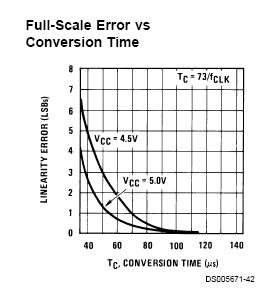
Figure 7. Linearity Error
There is no safety consideration regarding to this design project; the only thing that users may caution about is the 5V and 10V power supply.
Usability
Our project not only has the industrial potential but also is suitable for academic research. In the point of view of the multimedia industry, the application of audio processing is very important. For example, it is an apparent trend that the digital TV will replace the traditional TV in the future. I am sure that our project has the commercial value. In the point view of academic, we can apply many mathematic models our system to give a realistic result to support the theoretical proposition of audio processing. We think that our project can contribute to the multimedia industry as well as the academia.
The quality of our music is pretty good. In the part of voice, the quality is even better than our expectation since the frequency of human voice is lower that the sampling frequency of our project. In the part of music, since the music contains so much high frequency audio signal, the sample rate of our project could not capture those signals perfectly. Therefore, we did not expect the quality can be as high as the CD players. However, with the limitation of hardware, we think that we have optimized our system performance for the best quality, and we feel really satisfactory on our result. Besides, our program allows us to transfer the audio signals from the microcontroller to the PC at a baud rate of 115.2 Kbps. This design allows us to transfer audio signal and record them in the PC in real time. This result is also really satisfactory and reaches our expectation. Finally, since we spent so much to search for some extensively used algorithms in digital audio signal processing, the simulation of sound effects is really successful. We think that we did a good job for this final project.
In the beginning, we also wanted to apply more components to our project. For example, we could record music in real time into an SD card. However, there is not enough internal memory, which is only 2 Kbytes that we decided not to apply this component. I think if we could integrate our project with an external memory, we could have this function in the future. Besides, we also wanted to integrate this project with a wireless remote control that allows us to control our program anywhere in the effective range. However, since the wireless signal is not stable due to interference with other groups that we did not apply it eventually. Moreover, we wanted to use USB interface to communicate between the microcontroller and the PC. This design will not remove the data transfer bottleneck since the speed of serial port is high enough in our design, but it will make our project more compatible to all the PCs since USB is common interface nowadays. We think we could accomplish this part if we have more time to implement the USB device driver. Finally, we think the quality of music could also be improved if we use better external ADC chip with higher conversion rate. We also believe that with a higher budget, we could accomplish this part in the future to improve our system.
In this project, we use the pre-amplifier circuit of the previous project , "Sound Effect Processor". Also, we referenced a open-source website,"Music DSP Source Code Archive". Those algorithms that we found are well suitable for our sound effects.
Code of Ethics
1. The design of our system fulfills all the safety, health and welfare requirements.;
2. Our
system does not cause any real or perceived conflicts of interest to other
parties;
3. All the stating claims or estimates
are based on real data and correct;
4. We do not accept any
kinds of bribery in our project;
5. We promote the
understanding of technology, its lawful application, and potential
consequences. Our system is an excellent Karoke system to help people sing
better;
6. We maintain and improve
our technical competence and undertake technological tasks for others only if
qualified by training or experience, or after full disclosure of pertinent
limitations;
7. We DO seek and
acknowledge any kinds of reasonable criticism on our work to improve our system,
and make it excellent. Moreover, we will give out all the credits to their
valuable contributions. Please refer to our reference section for details;
8. Our design does not cause
any harmful effects to others,
their property, reputation, or employment by unlawful action;
9. We help and supervise
with each other to make sure our behaviors to follow
this code of ethics.
The source code for the console program is edited in the Microsoft Visual Studio environment. The source code is the complete project created by the version of Visual Studio 2005 .NET. All the configurations have been setup, but you need to install Platform SDK as mentioned before. After you install the SDK, please follow the instruction found in the SDK to setup the Visual Studio environment to include the library and header files of the SDK.
The source code for the Java application is edited in the eclipse environment. The source code is the complete project created by the version 3.1. However, the Java Mail 1.5 and Java Bean Activation Framework must be installed first. The "mail.jar" and "activation.jar" must be included in the library directory of the project configuration.
The console program is stored in the "ConsoleApplication.zip" file. If the user extracts the zip file, the directory, "ConsoleApplication" is created with all the associated subdirectories. The Java application is stored in the "gui.zip". If the user extracts the zip file, the directory "gui" is created with all the associated subdirectories.
In order to run the application, the user opens the gui/gui directory after he extracts the "gui.zip" file. He should run "startgui.bat [COM PORT #]" to launch the application. (Note: he can run the application in the eclipse environment. However, he should modify the command line argument set in the eclipse project. The default argument is set to COM6. Moreover, if he modifies the code of the console program, he should place the updated executable of the console program called, "ConsoleApplication.exe", into this directory.
The MCU source code is edited in the CodeVision Warrior environment. After you compile the code, you can simply program the image into the STK-500 and start using the program.
When the user wants to start this multimedia system, he should reset the MCU program first and then launch the PC software application. If he wants to reset the MCU without re-launching the PC software, he should make sure that the multimedia system has been turned off before.
ConsoleApplication.zip -- console program
gui.zip -- the Java application
| Schematics GIF Version | Schematics Visio Version | |
| ATMega32 | microcontroller | microcontroller |
| Microphone Preamplifier | Pre-amplifier | Pre-amplifier |
| ADC0801 | ADC0801 | ADC0801 |
| DAC0808 | DAC0808 | DAC0808 |
| Component | Quantity | Price | Remark |
| ATMega32 | 1 | $8 | Lab equipment |
| Breadboard | 1 | $0 | From trash bin |
| DAC0808LCN-ND | 1 | $1.74 | Digi-key |
| ADC0801LCN-ND | 1 | $9.61 | Digi-key |
| LM358 Operational Amplifier | 2 | $0 | Lab equipment |
| LM7111 Operational Amplifier | 1 | $0 | Lab equipment |
| Speaker | 1 | $0 | Sheng-Yi Shih's |
| PC | 1 | $0 | Ah Yud Chan's |
| Microphone | 1 | $0 | Borrowed from Jimmy Chen |
Accomplishment Parts
| Researching hardware parts | Sheng-Yi Shih, Wing Mau Cheung, Ah Yud Chan |
| Building the ADC Circuit and PreAmplifier Circuit | Ah Yud Chan, Sheng-Yi Shih |
| Testing the ADC Circuit and PreAmplifier Circuit | Ah Yud Chan, Sheng-Yi Shih |
| Building the Microphone and PreAmplifier Circuit | Sheng-Yi Shih, Ah Yud Chan, Wing Mau Cheung |
| Testing the Microphone and the PreAmplifier Circuit | Sheng-Yi Shih, Ah Yud Chan |
| Building the DAC Circuit and PreAmplifier Circuit | Ah Yud Chan, Sheng-Yi Shih |
| Testing the DAC Circuit and PreAmplifier Circuit | Sheng-Yi Shih, Ah Yud Chan, Wing Mau Cheung |
| Implementing the microcontroller Code | Wing Mau Cheung, Ah Yud Chan, Sheng-Yi Shih |
| Researching the Algorithm of Sound Effects | Sheng-Yi Shih, Wing Mau Cheung |
| Implementing the PC Server Code | Ah Yud Chan, Sheng-Yi Shih |
| Surveying the Protocol between PC and microcontroller | Ah Yud Chan, Sheng-Yi Shih |
| Integrating the overall Project | Ah Yud Chan, Wing Mau Cheung, Sheng-Yi Shih, |
| Writing the Report | Wing Mau Cheung, Sheng-Yi Shih, Ah Yud Chan |
Other Parts
| Studying the Transmitter and Receiver | Wing Mau Cheung |
| Studying the USB Module | Ah Yud Chan |
| Studying the Specification of SD card | Ah Yud Chan |
MSDN: We survey the some protocol of the communication of serial port in this famous websites.
Java Tutorial: It is the official site of JAVA that provides very clear documentation