Contents
- Introduction
- High Level Design
- Hardware and Software Design
- Results
- Conclusions
- Appendix A: Schematic
- Appendix B: Source Code Listing
- Appendix C: Parts/Costs Listing
- Appendix D: Task Division
- Appendix E: References
Introduction
Our final project is a conceptual prototype of a digital receipt system. The basic idea is when making a purchase with a credit or ATM card, the transaction information is automatically packaged and sent to a webserver where it can be logged in a database. A web interface would then allow consumers to log into their accounts and view their transactions online all in one place.
High Level Design
Rationale
The idea for this project came from a course Hain-Lee was taking concurrently with ECE 4760; CS 5150, Software Engineering. One of the potential projects was titled “Paperless World” and entailed developing a software system that would allow for paperless receipts. Consumers would benefit from the convenience of viewing/managing all their receipts online, and retailers would benefit from the additional information about their customers in terms of what they buy, as well as being able to say they are going green by reducing paper consumption. Hain-Lee was really interested in working on that project but unfortunately was not part of the group that was chosen for it. Thus, it became an idea for a final project for ECE 4760.
The idea of paperless receipts (or “digital receipts” or “e-Receipts”) may be new to many consumers, but there are already a couple small companies that have begun setting up such systems. An example is a company called Third Solutions, which runs myreceipts.com (consumer facing) and digitalreceipts.com (for developers and retailers).
For our final project we decided to create a simple conceptual prototype of a digital receipt system, mostly for educational enrichment. This includes interfacing the necessary hardware as well as an elementary web interface to view transactions processed by the hardware.
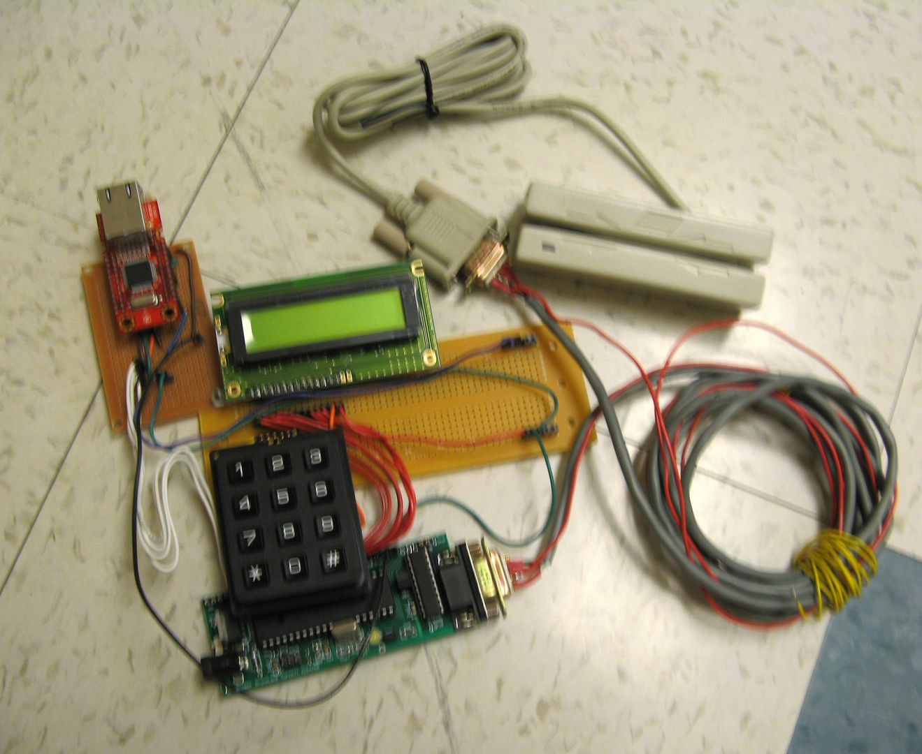
Logical Structure
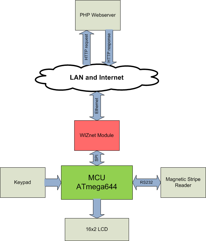
The above is a basic block diagram of the hardware connections needed. The keypad and LCD components each occupy one of the four available 8-bit ports on the MCU. Many magnetic stripe readers we found used an RS-232 interface, which only occupies two pins on the MCU. An Ethernet module is required to enable the MCU to send information over the internet.
The general procedure of operating the system is as follows:
- The “cashier” uses the keypad to enter an amount to be charged, which is displayed on the LCD display.
- After the amount is entered, the “consumer” is prompted to swipe his/her credit card through the stripe reader.
- The MCU receives the decoded data from the stripe reader and parses it to extract the desired data most relevant to the transaction (e.g. the consumer’s first and last name). It also parses the amount entered on the keypad and builds a packet containing all the information pertaining to the current transaction.
- The MCU sends the data to the Ethernet module, which sends the transaction information to a PHP script, and then waits for the response.
- The PHP script takes the data and stores it in a database. A response is sent back to the Ethernet module containing the result (success or failure).
- The Ethernet module receives the response and passes it to the MCU. A confirmation/status message is displayed on the LCD to the consumer, and the process starts again for the next transaction.
This procedure is described and depicted in more detail in the program design section. After a consumer has made a transaction for the first time, an online account is automatically created under the consumer’s name on a website, where the consumer can log in and view his/her transactions. Because the focus of the course is on the microcontroller side, the website/web interface is fairly rudimentary but can be modified and extended with more powerful features and customization independently of the hardware.
Background Information and Relevant Standards
This section briefly goes over information and existing standards pertaining to magnetic stripe cards and the OSI reference model for network communications.
In a magnetic stripe card for financial transactions, there can be up to three tracks of data encoded. Tracks 1 and 2 are most often used for financial transactions, and track 3 is seldom used. Each track contains different types and amounts of information, but for our project track 1 is most relevant because it contains the cardholder’s name as well as other commonly used information such as card number, expiration date, etc. There are several standards associated with general magnetic stripe cards dictating everything from physical dimensions and sizes of such cards to the location of the various tracks in the stripe (refer to http://en.wikipedia.org/wiki/Magnetic_stripe), but the associated standard specific to financial transaction cards is ISO 7813. The ISO 7813 standard specifies the formats of each of the three tracks. This information was necessary if we wanted to parse data from the card reader on the microcontroller. For more information related to the ISO 7813 standard, refer to the list of References at the end of the report.
On the internet connection side, some knowledge of the OSI reference model is necessary. The model consists of a set of layers that are built on top of each other. The first layer is the physical layer, which defines the physical hardware components and the physical /electrical connections between them. The second layer is the Datalink (often called MAC) layer, and it handles the manipulation of bits and signals to construct logical sequences of units called data frames. The third layer is the network layer, which handles the routing of data through different networks. The layers above the network layer no longer deal with hardware and define protocols and applications for reliability, setting up connections, functionality, and security (refer to http://en.wikipedia.org/wiki/OSI_model). The main idea is that each layer talks only to adjacent layers and can be designed and modified independently of the others as long as the interfaces between each layer remains the same. Each layer has its own associated set of standards and/or protocols. For physical connections, an RJ-45 mag jack is required to plug in an Ethernet cable. The Ethernet standard, associated with the datalink layer, is IEEE 802.3 (Wi-fi is 802.11). The most common protocol in the network layer is IP (internet protocol), which handles naive transfer of data one hop at a time, throwing away packets if errors are detected. Other protocols used in our project and associated with higher layers are TCP (transmission control protocol associated with the transport layer) and HTTP (hypertext transfer protocol associated with the application layer).
Trademarks and Patents
To the best of our knowledge and searching abilities, the terms “e-Receipts” and “digital receipts” are not registered trademarks (which is why we can title our project as “Digital Receipts”). This project is for educational and demonstration purposes only, and is not at all intended for commercial application (as it is extremely insecure). We will not pursue any patents, as there are already fully featured and developed digital receipt solutions in the market.
Hardware and Software Design
Hardware Components
ATmega644 MCU + Prototype Board
There was no reason to use a different MCU than we had been using in class already, so we decided to stick with the ATmega644. We also built the prototype board with the custom PCB designed by Professor Land as described here. Because we needed serial communication we included the RS-232 connector on the board as well as a sampled MAX233ACPP chip.
4x3 Keypad
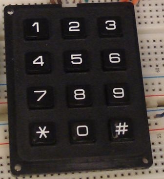
The keypad we used has buttons for digits 0-9, * and #. The lab already had 4x4 keypads, but we chose a 3x4 keypad because of cost (we were able to find a significantly cheaper 3x4 keypad). The keypad is matrix encoded and thus only occupies 7 pins of the MCU. Furthermore, the keypad scanning routine used in previous labs for 4x4 keypads could easily be adapted for the 3x4 keypad. Although a 4x4 keypad contains more buttons that can be used for additional functions, we can compensate by encoding simultaneous button presses on the 3x4 keypad.
16x2 LCD
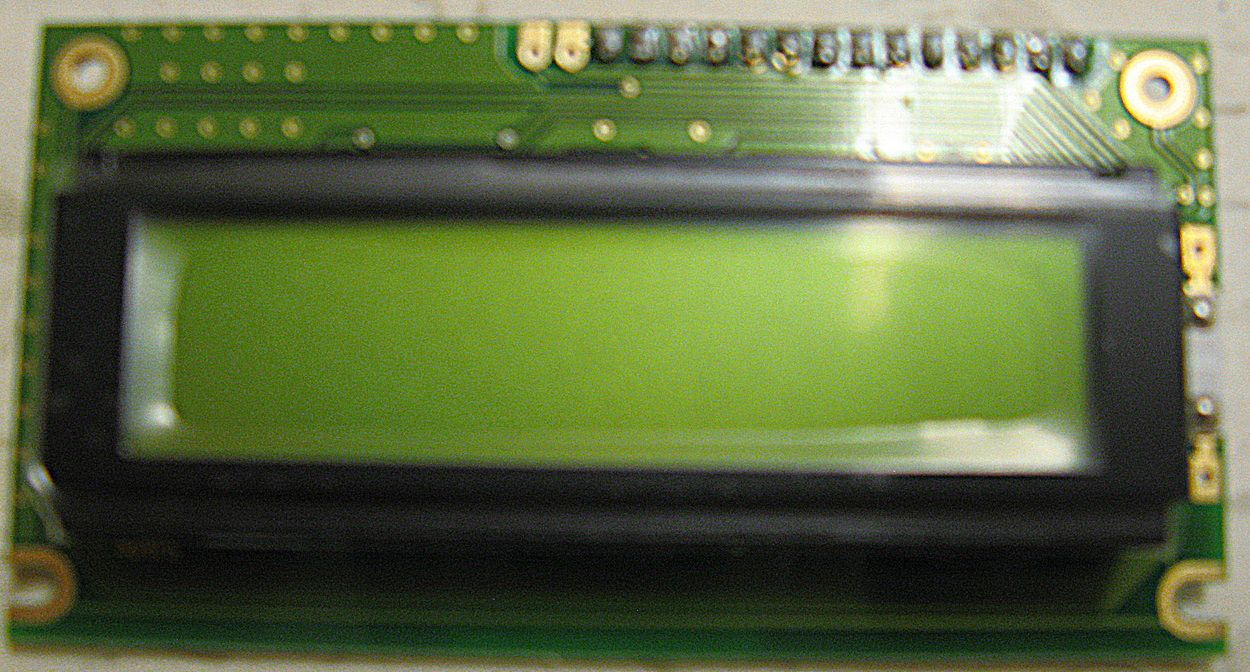
The LCD display included the standard HD44780 controller and occupied 7 pins of the MCU. Because it uses the same interface as in previous labs, the same LCD library could be used to drive it as well.
Magnetic Card Reader

On a credit card magnetic stripe, the cardholder’s name is stored only on track 1. Therefore, we needed to obtain a magnetic card reader that could read track 1. The card reader includes its own controller that can read the data from a magnetic stripe and send the decoded information over the serial interface. The serial interface occupies 2 pins on the MCU.
Ethernet Module
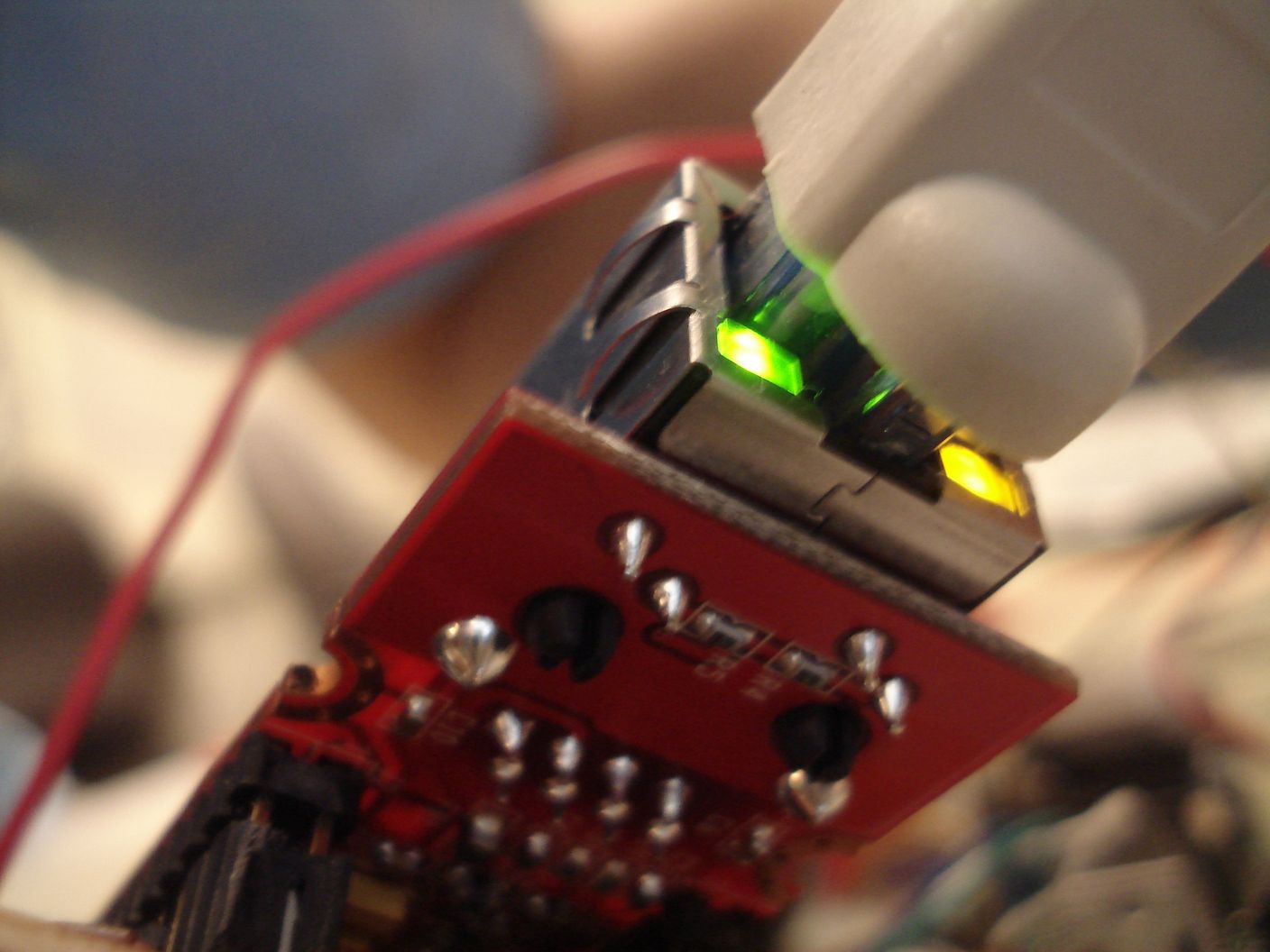
Because the card reader occupied the RS-232 UART on the microcontroller, we needed an Ethernet module that could communicate using a different interface. There were some Ethernet modules that supported a direct 8-bit interface, but this was not feasible because of the limited number of available pins. For this reason SPI was ideal because it only requires 4 pins on the MCU. The need for an SPI Ethernet module ruled out using a Lantronix module. Wiznet, on the other hand, manufactures a number of Ethernet modules that can communicate using SPI. The module we ended up using for the project is a Wiznet WIZ812MJ, which uses the Wiznet W5100 chip.
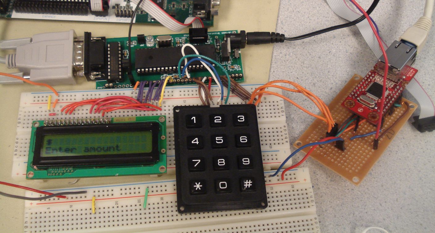
Connecting Everything Together
Before building the hardware necessary to interface everything together, we needed to consider the basic DC electrical characteristics of each component and the system as a whole. Although the MCU, keypad, and LCD are moderately low power (consume less than 100 mA altogether in typical usage), the RS-232 connection and the Ethernet module require a significant amount of current. The magnetic card reader draws about 10-12 mA and the Ethernet module itself can consume between 100-200mA. Thus, when stepping down a standard 9-16V power supply, we used a 1A, 5V regulator. 5V was used as Vcc for the MCU, card reader, and LCD display.
This lead to another issue; the Ethernet module requires a 3.3V supply voltage. Using a resistive divider to generate 3.3V from the VTG output of the MCU did not work. As soon as the Ethernet module was connected, the 3.3V dropped to below 2V. Although the MCU could run at 3.3V, this was not a viable option because both the LCD and magnetic card reader required 5V (the magnetic card reader requires a minimum of 4V). Thus a separate 3.3V power supply was needed for the Ethernet module. We used a lab power supply that was adjustable to 3.3V for this purpose.
The Vcc pin of the Ethernet module is the only pin that requires 3.3V (max 3.6V); the I/O pins are 5V tolerant according to the datasheet. Fortunately, the logic high voltage output of the Ethernet module is high enough to register as a high at the input of the MCU, as long as the 3.3V power supply can provide enough current.
A breakout board for the module was made for ease of integration, as shown below.

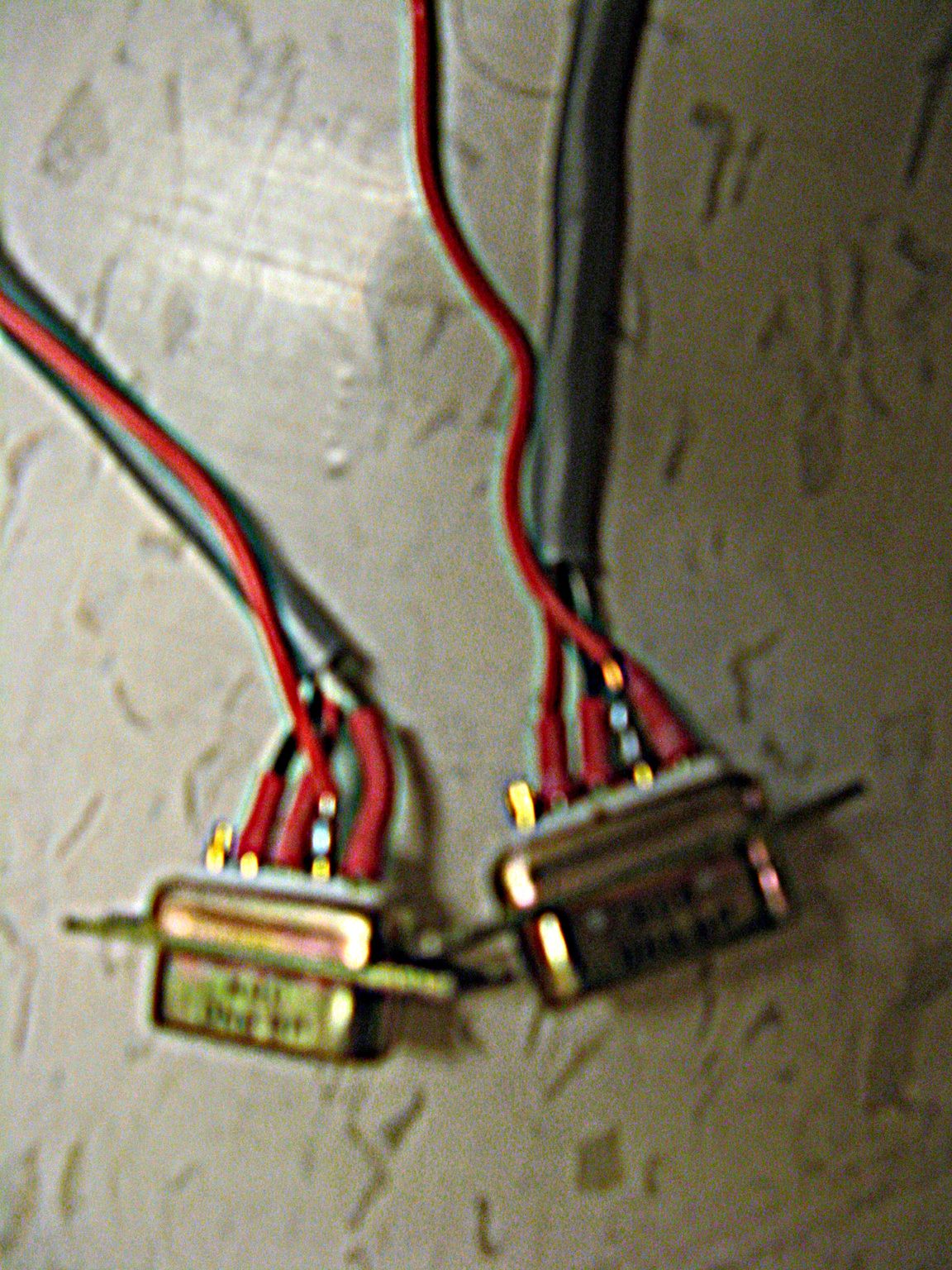
For the magnetic card reader, the particular model we bought is powered from the RS-232 port and thus doesn’t require a separate power supply. The first thing we noticed when the card reader arrived was that it had a female connector. The prototype board also had a female connector, and thus we ordered a 9-pin DB male to male gender changer. When that came in and we tried connecting, the card reader would not power on. We discovered that this was because the RS-232 connection on the prototype board did not have Vcc connected, and thus we had to solder a wire under the board to provide the voltage to power the card reader. When we connected the card reader to the RS-232 connector on the prototype board, we confirmed that the card reader was powered because of the LED indicator, but the prototype board was not receiving any data when a card was swiped. After asking the professor for ideas and doing some searching online, we found that this was because both the MCU and card reader are both Data-Communications-Equipment (DCE) devices, vs. a Data-Terminal-Equipment (DTE) device, such as a computer running HyperTerminal. A straight-through connection ties the transmit lines of both devices together and the receive lines of both devices together. Thus, we had to cross link the transmit/receive pins. A null modem cable serves this purpose, and luckily there was one hanging around the lab. This particular null modem cable only had 3 wires connecting both ends (the transmit/receive lines cross-linked, and a straight-through ground connection). We thus soldered an additional connection to provide Vcc as well. The null modem cable with the cross-linked receive/transmit connections and additional wire for Vcc is shown below:
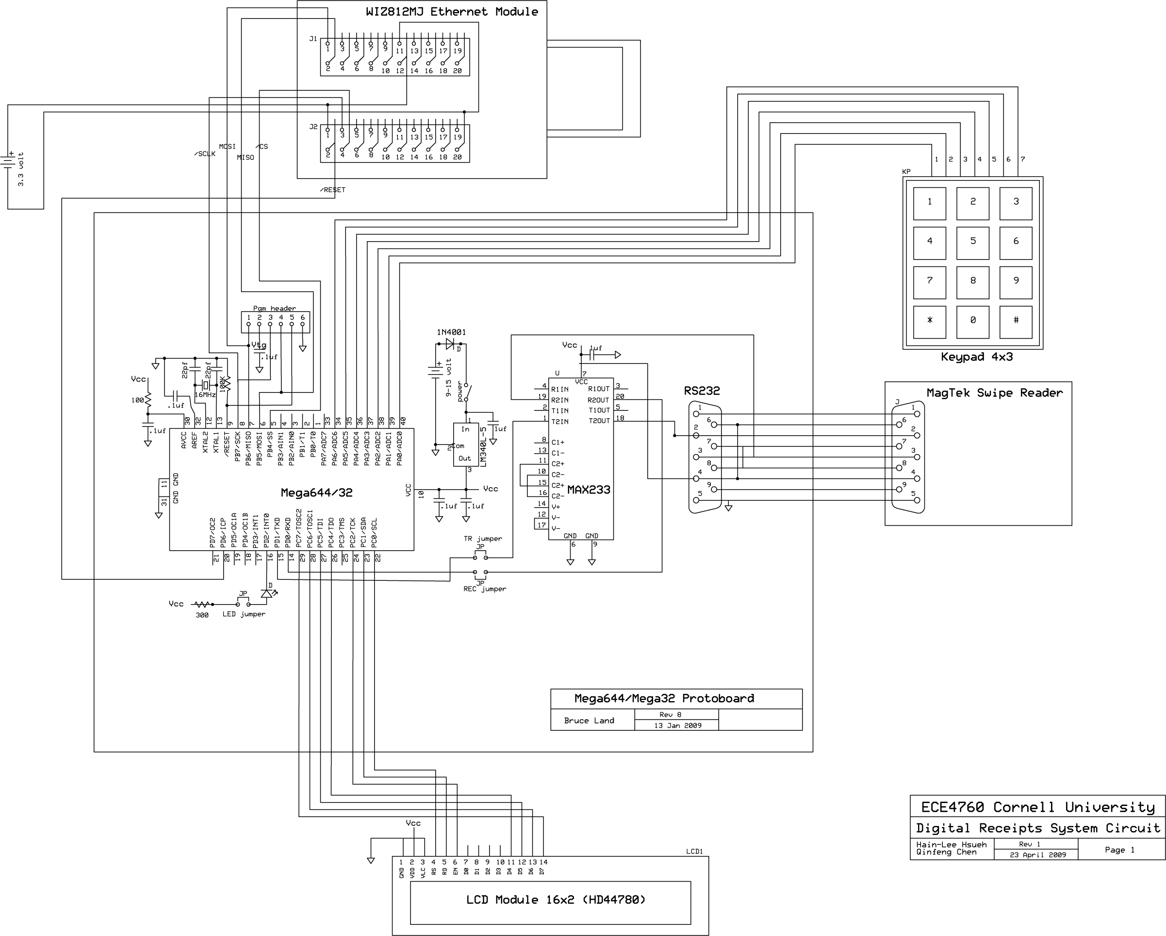
A schematic of the circuit can be found in the Appendix A.
Software Structure/Design
Main Program Structure
Let’s start with the main program structure. The overall structure of the main program is a state machine. The flow chart below depicts the different states and processes involved with each of them.
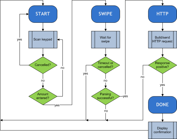
START
The START state is where the program waits for the cashier to enter a dollar amount on the keypad. Because of the limited number of buttons, only 2 buttons were available for “special” functions. We definitely wanted “Enter” and “Cancel” functions, along with a way to enter a decimal point. Thus, we chose the ‘#’ to indicate “Enter”, the ‘*’ key for the decimal point, and a simultaneous press-and-hold of the ‘#’ and ‘*’ keys for “Cancel.” We also arbitrarily limited the number of integer digits to 5 and number of decimal places to 2, although these can be easily changed in the code.
In summary, when the system is initialized to the START state, the LCD prompts the cashier to begin entering an amount. The digits are sent to the LCD display as the cashier presses buttons. They are also stored in a string buffer. The ‘#’ key is pressed when the amount is completely entered (which sets a flag in the software), the ‘*’ is pressed to enter a decimal point, and the ‘*’ and ‘#’ keys are pressed and held to cancel the order.
SWIPE
After an amount has been entered and confirmed, the program transitions to the SWIPE state. First, the program converts the sequence of digits entered by the cashier from a string to an integer (separate variables for dollars and cents). Then the LCD prompts the consumer to swipe his/her credit card through the card reader. During this time, the cashier can still cancel the order by pressing the ‘*’ and ‘#’ keys simultaneously. There is also a timeout counter that will automatically cancel the order if there is no card swiped within a period of time. When the consumer does swipe his/her credit card, the decoded information is set to the MCU to be parsed. The consumer’s name and credit card number are extracted from the data and stored in variables to be accessed later. In the event that the data from the card reader does not conform to the expected format, the system will cancel the current transaction and restart.
HTTP
When the information is successfully extracted from the magnetic card, the program then constructs an HTTP request containing the information pertaining to the current transaction. An attempt to connect to the remote server is made and the HTTP request is sent. The MCU expects an HTTP response from the server and examines it to make sure the transaction was successfully processed.
DONE
If the result of sending the transaction is successful, the program transitions to the DONE state, where the LCD displays a confirmation and thank you message to the consumer. After a few seconds, the program automatically performs a soft reset and transitions back to the START state to process the next transaction.
Keypad Debouncing State Machine/LCD Controller
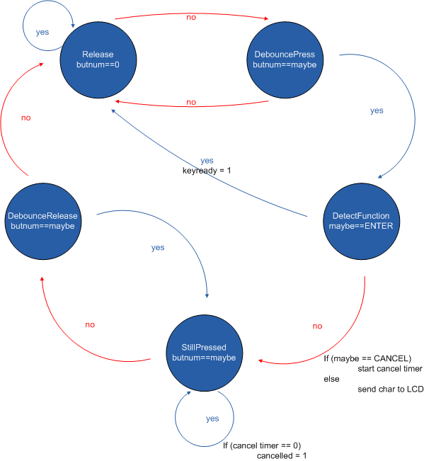
It was necessary to debounce the keypad in order for consistent behavior and performance. This was accomplished using a debouncing state machine, in which we also integrated the logic for detecting certain functions and sending characters to the LCD. The keypad debouncing state machine is based on the state machine we wrote for the DTMF dialer. First we had to modify the matrix encodings to correspond to the right ASCII values and/or specialized functions. We also included semantic logic in the state machine as well, for example prohibiting the user from entering more than 1 decimal point, more than 2 digits after the decimal point, etc. When a debounced key is detected, depending on what was entered already and what the detected button is, the state machine either sets a flag (for “ENTER” or “CANCEL”) or stores the corresponding ASCII value into a buffer and sends the corresponding ASCII character to the LCD. Refer to the commented source code in Appendix B for more details. The state machine diagram is shown below:
Communicating with the Magnetic Card Reader
For communicating with the card reader, we used Professor Land’s interrupt-driven serial communication code used in the keypad security code lab. This allowed us to make our program support concurrency selectively. When the program waits for a swipe (for the card reader to send data), it does not need to block, and the user can choose to cancel the transaction by pressing the ‘#’ and ‘*’ keys, or if a certain amount of time has elapsed, the system will automatically perform a soft reset.
When data from the card reader is received, it is parsed according to the track 1 format outlined by the ISO 7813 standard. When parsing of the card data and the entered amount on the keypad is complete, all the information is ready to be sent over Ethernet. If for any reason the data from the card reader does not conform to the standard, either due to misread swipe or other reason, then the program performs a soft reset and the amount must be entered again.
Ethernet Module Firmware
To drive the Ethernet module, we obtained firmware source code from the Wiznet website. The firmware code provided a HAL (defining descriptive names for register addresses, etc), SPI macros, register read/write functions, and socket functions. Although this code provided a huge convenience for us, it was necessary to make several changes in order to use for the ATmega644 and to get it to compile in our version of AVRStudio. It was also necessary to go through the firmware code and understand it in order to effectively debug – a great deal of time was spent studying the firmware code in conjunction with the datasheet to see what the firmware took care of and how to use it correctly.
Example uses of the Wiznet firmware were available from the iEthernet Circuit Cellar contest in 2007, which used a predecessor of our Ethernet module, the WIZ810MJ (we are using the WIZ812MJ).
For our specific application, we needed to configure the module to act as a TCP client in order to make an HTTP request to a remote website (web connections are established using TCP). To do this we needed to configure the module's IP address, the gateway IP address, and the MAC address. Connectivity took some time to obtain because of the way the network was set up in the lab and the fact that DHCP is not built-in. We were unable to ping our device, even after scanning the LAN to find a unique IP address within range, or using private IP addresses not routed on the public network. The only way we could get internet connectivity was by cloning one of the computer's MAC address and assigned IP address and disconnecting that computer from the network. Connectivity was confirmed by pinging the module from another lab computer and from a laptop on RedRover.
A test program was written exclusively to verify the operations of the Ethernet module before incorporating it with the project. This was a fortunate decision because the Ethernet module took up the most time in terms of getting all the components to work as expected. The first step was to make sure reading/writing registers to the module was working. The next was to ensure connectivity. And finally the last was to make a successful TCP connection. Each of these steps took much longer than anticipated and we needed to contact the manufacturer a couple times for help. An example output log file of a successful test connection can be found here (includes debugging print statements included in the firmware indicating which method is being executed).
On the Remote Web Server
On the remote web server, there is a PHP script that expects specific information that is passed to it, and adds data to a transaction database powered by MySQL. Besides the information about the transaction (consumer’s name, transaction amount, etc), the MCU also sends a parameter that tells the PHP script that the request came from the Ethernet module. This provides a very basic safeguard against anyone accessing the script using a web browser to add data to the database.
If all the expected parameters are provided, the PHP script adds the transaction to the database, creating a new user account if it is the first transaction for a consumer. Currently, the script creates default usernames and passwords for each name that it receives; the username being the first letter of the first name, followed by the last name in all lowercase letters with no spaces or non-alphabetical characters. The password is the person’s last name in all uppercase letters. Once an account has been created upon the first transaction, the person can log into the website and view his transaction history. The person also can (and should) change his/her password on the website as well. Login is implemented using PHP sessions, which are moderately secure (although almost every other aspect of the project is insecure).
If the PHP processing was successful, it returns a string that includes "<result>SUCCESS</result>" for easy parsing on the MCU. If invalid parameters are provided, or there are errors with database operations (e.g. if the database happens to be down at the time), then the PHP script will return an ERROR message that the MCU can also easily parse. The LCD display will notify the user of an error on the webserver side, and the system performs a soft reset.
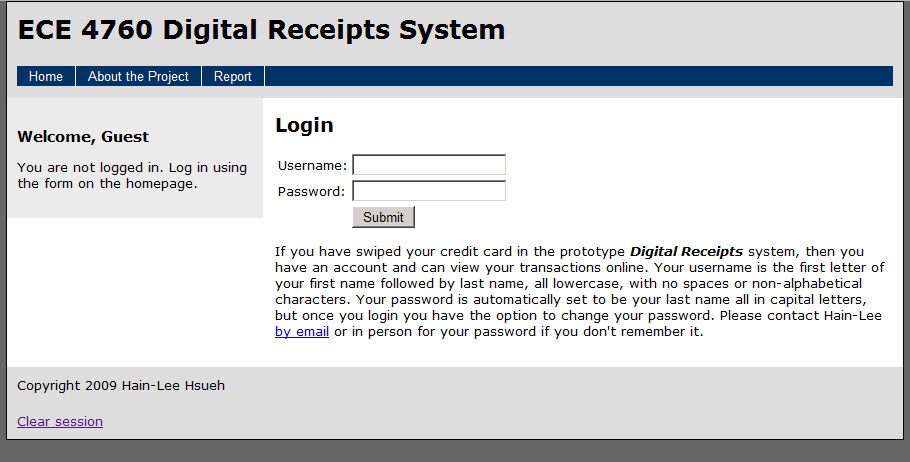
For the consumer web interface, there is a login form that validates usernames and passwords against the database of existing accounts and transactions. If an invalid username or password is entered, an appropriate mesage is shown and transactions cannot be displayed. Screenshots of the web interface are shown below. The actual live web interface can be found here.

Results
The resulting system was in general a success. It was able to allow numerical input without allowing invalid numbers (such as multiple decimal points or fractional cents). It was able to read in data from the card reader, parse the data correctly, and make a successful HTTP request to a PHP script. The system was also able to detect errors throughout the transaction process (timeout due to inactivity, unable to connect, and errors on the PHP side). Concurrency was supported selectively in that keypad input was only monitored during numerical input or when “listening” for a “CANCEL” while waiting for a card swipe.
There were some circumstances, however, that resulted in delaying of execution. The first is that when the system first powers on, it must wait a couple sends before the user can do anything. This time was necessary to perform a hardware reset of the Ethernet module via software in order to properly initialize it. 3 seconds provided enough time for the Ethernet module to properly power on and be ready for execution. Delays were also implemented when displaying status messages on the LCD display, in order for them to persist long enough for the users to read (timers were interrupt-driven to allow potential for concurrency). When the user cancels the transaction either while entering numbers or when the system is waiting for a card swipe, the LCD displays “Cancelled” for a brief amount of time before interaction can begin again. An exception to extending the duration of a status message is when the data is being processed to be sent over Ethernet. Status messages such as “Building HTTP request,” “Sending data,” and “Waiting for response” were only displayed for as long as the task took, in order to make the transaction quick. If the internet connection is fast, then the LCD “flickers” because the status messages change quickly.
Accuracy was not difficult to achieve because we only needed to support up to 2 decimal places, although we arbitrarily placed a limit on the number of digits before the decimal point to prevent any possibility of integer overflow and from running out of room on the LCD line.
In terms of usability, the system was easy and smooth to operate so long as card swipes were done smoothly. We asked a couple people in lab to try it out (using their own credit cards if they were comfortable doing so, or ours otherwise) and feedback was generally positive. On the MCU side, the status messages on the LCD served as visual cues for what the program was currently doing. Prompts also helped facilitate proper procedural operation (e.g. “Enter amount” and “Swipe card”). Factors such as the timeout duration could be adjusted to optimize the usability experience (e.g. not timing out before a person can get his/her credit card out). On the web interface side, logging in, viewing transactions, and logging out are also simple, partially because those are the only operations. Knowledge of how the system automatically creates usernames and default passwords, however, was necessary for a consumer to login (the system by default creates a username by combining the first letter of the first name, followed by the last name, all lower case, no spaces or non-alphabetic characters. The default password is the person’s last name in all uppercase letters). Once the person logs in, he/she has the option to change the password with ease.
A brief AVI video showing the system in use can be found here.
Conclusions
Expectations and Other Thoughts
Our primary goal was to be able to enable the microcontroller to connect to the internet and make persistent changes (in this case, by inserting data into a database). In this sense, our design certainly met our expectations. One thing we did not expect, however, was how close we were to the $75 budget (refer to Appendix C). The little details added up and we had to take care in finding cheap prices for components. The cost could have been reduced by a few dollars if we chose to leave the circuit on breadboards which we owned previously, and if we built more of the hardware ourselves, mainly the ethernet module. One of the most frustrating challenges (after finally managing to get each component working individually with the microcontroller) was the inability to use HyperTerminal to debug the system with the card reader connected, since the card reader occupies the RS-232 connection. As a result, we had to substitute print statements with short messages on the LCD if the card reader was connected.
If we were to do the project again, there are a couple things we would have done differently. In our implementation the system performs a soft reset if it detects an invalid card has been swiped. Often times a "faulty" swipe of an authentic credit card resulted in unsuccessful parsing of the data, which would then cause a soft reset. To make the system more usable, we would have allowed for an arbitary number of retries rather than resetting after the first failure. In terms of hardware, we would've opted for one power supply for everything rather than separate power supplies for the MCU and the Ethernet module. Adding circuitry to shift 3.3V levels to 5V levels also could have made the interface between the MCU and the Ethernet module more robust. Also, a larger LCD (perhaps a 20x4) could have allowed for more descriptive status messages, which would make the system more usable and also aid in debugging.
Security Issues
Security is a very relevant concern with our project. Although all the processing on the microcontroller is fairly secure, the Ethernet connection is inherently insecure – anyone sniffing the network and viewing packets can see what is being transmitted in plain text. It is for this reason that we only transmit the last 4 digits over the internet connection. Thus, a future addition would be for encryption of data before being sent. We did brainstorm some possible encryption schemes (such as using the PHP session id which changes with each new session), but ultimately we didn’t have enough time to implement any of them. RSA encryption is commonly used on commercial websites, but not very feasible on an 8-bit microcontroller. If we were to do this again, however, we would’ve thought of a basic encryption scheme beforehand. Security is also an issue on the web interface side as well, since the information is stored in plain text in the database. With more time, the web interface could also be made more secure.
Since our project dealt with sensitive information without much inherent security, we had to take precautions to protect the information. In order to test the card parsing code, we displayed the parsed parameters on the LCD display (first name, last name, and credit card number). We never connected the system to the internet during this testing process in order to prevent sending someone's credit card number completely exposed. Once we got the parsing code right, immediately after parsing the credit card number, we replaced the first 12 digits with '*' so only the last 4 digits were visible. Thus, a full credit card number is never sent over the internet in any circumstance. Another safeguard we took was not parsing/sending any other information on the credit card besides name and the last 4 digits of the credit card number. Information such as expiration date, CVC security code, and other discretionary information were not even parsed. Each time a transaction is completed, the system performs a soft reset which entails explicitly zeroing all the bytes in the buffer where the card data is stored, clearing the information from the previous transaction completely.
Meeting Standards
Because our design made use of hardware “modules” rather than homemade hardware, we did not have to worry much about conforming to standards because each module ensured they themselves conformed to their respective standards. The card reader itself has a controller that reads only track encodings that conform to the ISO 7813 standard. The Ethernet module takes care of creating packets with headers, sequence numbers, bit padding, TCP handshake, etc. The only protocol we needed to conform to was the HTTP protocol. This was necessary to make valid requests and parse expected HTTP responses.
Intellectual Property Considerations
Although the ideas of the project were inspired from a potential project in a software engineering course, we developed the electrical circuits and physical set up on our own. As undergraduates, we retain ownership and copyrights of our original designs and original code.
As mentioned throughout the report, our source code includes work done by other entities. The firmware to drive the ethernet module was obtained from the WIZnet website, and slight modifications were made to it to get it to work with our particular microcontroller and compiler. Example uses of the firmware code were also available from Circuit Cellar, although none of the examples we looked at were specifically included in our project. In addition The UART implementation we used during the course is written by Joerg Wunsch. We also used Professor Bruce Land's interrupt-driven serial communication code to interface with the magnetic card reader. The keypad scanning routine is also largely based off Professor Bruce Land's code from a previous lab. Lastly, the LCD library to drive the LCD is provided by Scienceprog.com and distributed under the GNU Public License (http://www.gnu.org/licenses/gpl.txt).
We did not need to reverse engineer any designs nor sign any non-disclosure agreements to obtain sample parts. As mentioned in the beginning of the report, commercially developed digital receipt systems already exist and this project was done purely out of educational enrichment. Thus we are not pursuing any patent opportunities. We also do not see any potential publishing opportunities either, aside from informal publishing such as this lab report or on a blog targeted towards hobbyists.
Ethical Considerations
We followed the IEEE Code of Ethics throughout the development of our project to the best of our ability. The nature of our project did not pose any potential threats to the physical health and safety of the public, but to information/identity safety/security. According to rule 1, we have consistently made decisions that ensured the safety of both the public and ourselves and were aware of the responsibility upon these decisions. As mentioned before, when testing our card data parsing code, we prevented any possibility of sending complete credit card numbers over the internet by disconnecting the ethernet module. For user testing, we did not push people to use their credit cards if they were not comfortable doing so. We also limited the information that was parsed and stored in the database.
For rule 2, no conflicts of interest that we are aware of arose during the project and had we encountered any we would have tried our best to immediately resolve them.
In line with rule 3, the results of the project are accurate and realistic and appropriate figures, images, and source code have been provided to support our claims in an unaltered manner.
Concerning rule 4, bribery was not involved in the development of the project (although it conceivably could have happened since we were dealing with data from credit cards) and we would have immediately rejected it if it occurred.
For rules 5 and 6, we have strived to improve our understanding of the technologies used and their potential applications through experimentation and testing, and we did not try to undertake tasks for others that we weren't qualified for. Much time was spent to understand the provided WIZnet firmware in order to deepen our understanding of the ethernet module used. The documentation/datasheets were also studied in detail.
For rule 7, we willingly accepted technical advice and criticism of by any and all parties and sought help from the TA's and the professor when needed. Our report gives due credit when referencing other people's work.
In accordance with rule 8, we were polite and courteous to our peers in the lab (regardless of race, religion, gender, disability, age, and national origin) and offered our help when it was asked for (some groups needed to borrow a serial gender changer that we had, which we let them use).
In accordance with rule 9, we avoided injuring others, their property, reputation, and employment. In dealing with sensitive information we did not try to do anything malicious (e.g. storing people's complete credit card information with the intent to deceive or exploit).
Legal Considerations
Since the project does not use any radio frequency communication, it is not subject to any FCC regulations. As mentioned earlier, this project does not infringe on any existing copyrights or patents, nor are we seeking any form of profit. The project was purely for educational enrichment and is not intended for use outside of a classroom environment.
Appendix A: Circuit Schematic
Appendix B: Source Code Listing
MCU C code
- main.c
- wiznet.h
- keypad.h
- keypad.c
- lcd/lcd_lib.h
- lcd/lcd_lib.c
- uart/uart.h
- uart/uart.c
- w5100/w5100.h
- w5100/w5100.c
- w5100/types.h
- w5100/spi.h
- w5100/socket.h
- w5100/socket.c
PHP/MySQL code
Appendix C: Parts/Costs Listing
| Item | Cost | Source |
|---|---|---|
| Custom PCB for MCU | $4.00 | 4760 Lab |
| MAX233ACPP | sampled | Maxim IC |
| ATmega644 | sampled | Atmel |
| 40-pin DIP socket | $0.50 | 4760 Lab |
| 20-pin DIP socket | $0.50 | 4760 Lab |
| Male headers for custom board | $1.65 | 4760 Lab |
| 12V Power supply | - | previously owned |
| 3.3V lab supply | $5.00 | 4760 Lab |
| RS-232 Connector | $1.00 | 4760 Lab |
| 4x3 Keypad (KEYPADSM) | $2.20 | Futurlec |
| Female headers for keypad | $0.70 | 4760 Lab |
| Male headers for LCD | $0.70 | 4760 Lab |
| Female headers for LCD | $0.70 | 4760 Lab |
| Powertip 16x2 LCD (PC1602LRU-FSO-B) | $3.00 | Bonanzle.com |
| Ethernet Module (WIZ812MJ) | $15.99 | WIZnet |
| Small Protoboard | $1.00 | 4760 Lab |
| Female headers for ethernet module | $0.35 | 4760 Lab |
| Magtek Mini Swipe Reader (21040071) | $34.90 | POSSavings.com |
| RS-232 null modem cable | free | 4760 lab |
| 6 inch prototype board | $2.50 | 4760 lab |
| Total Cost | $74.69 |
Appendix D: Task Division
| Protoboard for MCU | Qinfeng |
| Protoboard for keypad and LCD | Qinfeng |
| Ethernet module firmware porting | Hain-Lee |
| Ethernet module hardware/software testing/debugging | Hain-Lee |
| Protoboard for ethernet module | Hain-Lee |
| PHP+MySQL/web interface | Hain-Lee |
| LCD/keypad/program software structure | Both |
| Magnetic card reader hardware/software testing/debugging | Both |
| System testing/debugging | Both |
| Project report | Both |
| Budget record keeping | Hain-Lee |
| Project website | Hain-Lee |
Appendix E: References
Datasheets/Documents
Vendor Sites
Borrowed Code/Designs
- W5100 firmware from WIZnet
- LCD Library from Scienceprog.com
- UART implementation by Joerg Wunsch, distributed from the ECE4760 website
- Interrupt-driven serial routines from Bruce Land
- Keypad raw scanning routine from Bruce Land
- Website HTML/CSS template code from Dreamweaver