Introduction
The Holonomic Drive Vehicle with Stochastic Evolution is an autonomous mobile robot that uses an evolutionary algorithm to learn how to move in a straight line.
The robot initially moves in arbitrary directions and then compares its motion to the desired motion. It combines motion instructions from each iteration to improve its motion until it matches the desired trajectory. The vehicle is essentially self-learning and autonomous. Ultimately, it is designed to learn on its own through experimentation.
High Level Design
Inspiration
The idea for this project came from our interest in robotics and the popular field of robotic evolution and learning. Knowledge of the inner-workings of optical mice was provided by a previous project in which position tracking was desired. Seeing other robots, such as the RoboCup robots, effortlessly move in any direction using omni-directional wheels was an inspiration to use them on our project.
Background Math
In order to determine the motion of the robot, the information from two optical mouse sensors were combined using trigonometry and linear algebra. The motion at each of the sensors is read as X and Y translation information relative to each imaging sensor. This X and Y translation is a combination of translational and rotational motion. In order to determine the actual motion, the expected X and Y information from each sensor was calculated, assuming the translational and rotational motion was known. These equations were then combined as matrices and solved using a least squares fit in order to find the actual translational and rotational motion from the measured X and Y motion from each sensor. A least squares fit was used because the two optical sensors will give four measurements, when only three directions are of interest. The least squares fit allows two values to be combined to find a value that minimizes the error between each.
Logical Structure
Our project contains three major parts: optical position sensing, motor control, and the evolutionary algorithm. The optical position sensing consists of two optical mouse sensors, which each track two-dimensional movement. By using two sensors, we can determine the X and Y position and the rotation of the robot. The three motors are controlled by H-bridge motor drivers which receive a pulse-width modulation (PWM) control signal from the microcontroller. Each motor powers one of the omni-directional wheels used to drive and steer the robot. The evolutionary algorithm selects control signals to send to the motors based on the correlation between the optical position data and the desired path.
Hardware/Software Tradeoffs
We made many compromises in this project due to budget constraints, hardware availability, and microcontroller capabilities. We initially planned to use integrated circuit (IC) H-bridge chips (TAS5342, originally designed for audio applications) to control the motors [schematic | layout | photo], but we were unable to generate the precise, high-frequency PWM outputs that the IC required with enough processing cycles left over to execute our remaining code. Consequently, we implemented H-bridge circuits using discrete components to allow for and more flexibility and much lower frequency PWM generation.
We also wanted to implement wireless communications for communication between the vehicle and a PC, but were constrained by both fiscal and time budgets.
Standards
The primary standard that we considered was the Electronic Industries Association (EIA) standard for RS-232 serial communication because we used an RS-232 serial interface to analyze motion data in MATLAB on a PC. Since we used commercially developed RS-232 transceivers and the integrated RS-232 peripheral on the ATmega644, we were easily able to comply with the standard.
CAD drawings, circuit schematics, and PCB layouts were prepared with reasonable engineering practices in mind.
Intellectual Property
Though self-learning robotics is a popular research field, we are not aware of any patents that involve the same evolutionary implementation or the same desired end result.
Implementation
Hardware Design
The hardware essentially can be divided into two main sections: mechanical and electrical. The mechanical hardware consists of the robotic vehicle, including the chassis and wheels, and the electrical hardware consists of the circuitry used to power and control the robot.
Chassis
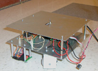
The robot consists of an 8-inch by 8-inch metal chassis [photo] mounted with three sets of omni-directional wheels [photo], powered by DC motors. All control hardware, including the ATmega644, H-bridges, and optical sensors, were contained on circuit boards mounted to the chassis. The chassis is machined from 0.060 inch thick steel sheet. It contains mounting holes and standoffs to hold the various components, and mounting brackets to support the motor and wheels. The wheels are made of plastic and are fitted to a steel drive shaft that is connected to the motors. We fabricated the chassis parts in the Cornell University Emerson Machine Shop and the CAD drawings for the chassis and motor/wheel holders are available here.
Motors
The three DC motors [photo] were salvaged from discarded inkjet printers. They can operate within a wide voltage range and are small. The motors are designed to be geared, so they operate at very high speeds while unloaded, and do not provide significant torques at most speeds. Since the vehicle's movement is learned based on position and is independent of the motor parameters, the motors do not need to be, and are definitely not, the same. The motors are powered by a 16V, 3.3A laptop power supply.
H-bridge Motor Drivers
Each of the three H-bridge circuits controls one of the wheel motors. The purpose of the H-bridges is to drive the motors in either direction and with a variable voltage. Each H-bridge consists of four MOSFETs (two NMOS and two PMOS), four BJTs (two NPN and two PNP), and several resistors. The transistors are used to properly drive the FETs and to ensure that only one of the FETs for each half-bridge is on at any time. [schematic | photo]
Optical Sensors
The two optical sensors are Avago Technologies ADNS-3080 High-Performance Optical Mouse Sensors. For correct operation, they are paired with a clip, lens, and high-brightness red LED, also from Avago Technologies. Each sensor is mounted on a printed circuit board [schematic | layout | photo] designed according to the specifications in the ADNS-3080 data sheet. The optical sensors send motion data to the ATmega644 over Serial Peripheral Interface (SPI). Level converters, in the form of voltage-dividers, are also included between the microcontroller and sensors so that the inputs to the chip are 3.3V instead of 5V, since the ADNS-3080 operates on 3.3V and does not have 5V tolerant communications inputs.
ATmega644
The ATmega644 microcontroller is mounted on a target board designed and provided by Prof. Bruce Land. The target board is modified with a higher current voltage regulator which dissipates heat better because it is in a larger package. We also added an external power switch and directly wired the 16V power supply input to the board. The external power switch was installed in the top chassis plate to facilitate easy switching.
Software Design
The software consists of several separate sections of code for different aspects of the project functionality.
Evolutionary Algorithm
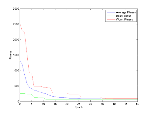
Paired with a cost function related to the desired output, the algorithm can determine an optimal solution to a given problem that minimizes the known costs (at least locally). By interacting with the environment, the robot acquires data and associates the action with a corresponding result. This result is compared to the desired output and permutes the control logic to try and reduce the error. A population of 25 members, with phenotypes to represent the motor control voltage, is developed and used to develop better solutions. Each epoch, all the members of the population are mutated in at least one of two ways: cross-breeding and random mutation. Cross-breeding selects a random portion from either the beginning or end of the phenotype and switches it with another random member's phenotype. In addition, with a 30% chance, a few bits in the phenotype may be randomly flipped. Once the member's phenotype has been mutated, the phenotype executes on the hardware and the result from the mouse sensors is recorded. This is then compared with the desired output and the fitness is determined. If the fitness is better than before (closer to zero), the new phenotype replaces the original. This process continues for each of the members, over many epochs, until a satisfactory set of solutions is found. A plot of the fitness for a simulated experiment is shown below.
Pulse-Width Modulation (PWM) Generation
The PWM software generates six 1 kHz output signals with variable duty cycles - two signals to control each motor. The PWM is generated in a 100kHz interrupt routine. Every interrupt, a counter is decremented (from a max of 100) and compared to zero. When the counter is still positive, the motor is turned on in the specified direction. After 100 cycles, the counters are reset, leading to a 1kHz PWM frequency. Each H-bridge receives two signals, one for each half-bridge. The two signals represent the two directions that each motor can go. The PWM generation routine ensures that the H-bridge is off, briefly, before turning on in the other direction to ensure that shoot through and other unwanted effects are avoided. Generating the PWM manually through an interrupt allows the pins to be arbitrarily specified and allows as many channels to be generated as desired.
Optical Sensor Communication
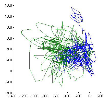
The ATmega644 communicates with the ADNS-3080 optical mouse sensors via an SPI serial interface. The ATmega644 is configured as a master, with both optical sensors configured as slaves. The communication signals use four-wire SPI - SCLK (serial clock), MOSI (master output, slave input), MISO (master input, slave output), and CS (chip select) - and a reset signal. The software reads X and Y motion from each sensor and uses this data to determine the overall motion of the vehicle. Two optical mouse sensors are required in order to extract the rotational motion since a single sensor only provides motion along two linear orthogonal directions. The two sensors are managed using independent chip select and reset lines. The plot below shows the X and Y position of two optical sensors.
Position Calculation
The two sets of X and Y motion information from the optical sensors are combined to determine the overall translational and rotational motion of the robot. The position calculation takes into account the extra information provided by the sensors, since only three degrees of freedom are present, but the sensors give four measurements, using a least squares algorithm.
Results
Speed of Execution
The evolutionary process takes approximately an hour to complete. The vehicle runs a 1 second tests approximately every second until a valid movement trajectory has been obtained. The robot moves with a reasonably high velocity, so this reduces the amount of time the evolution takes. Since many of the calculations only occur occasionally, the speed of execution for each subroutine is not significantly important. The most accurate routines are for PWM and SPI. The PWM occurs at 100kHz as dictated by the internal hardware timer.
Accuracy
The accuracy of the evolutionary results is primarily limited by the accuracy of the optical mouse sensors and the position tracking that can be determined from them. We also encountered some issues with insufficient motor torque causing difficulties in moving the robot. The motors were incapable of turning at lower voltages and also had difficulty starting to move in some situations when stuck against edges or bumps. The inconsistency of the motors could also contribute to inaccuracy, even if the optical sensors worked perfectly, since the motion would not match for each trial.
The surface on which the robot is moving has a significant impact on its performance and the accuracy of the results. The optical sensors do not work well on surfaces that are highly reflective or transparent, such as glass, or significantly textured, such as thick carpet. The wheels do not roll well on surfaces that have a high rolling resistance, such as carpet. Additionally, unlevel surfaces cause the robot to gravitate to the lowest point, since the omniwheels allow sideways rolling.
Safety & Interference
There are a few safety concerns involved with our project. Primarily, the robot can move very quickly and in unexpected ways. Thus, it is important that any operators or observers stay out of the way to avoid injury. Additionally, the long power cable could pose a tripping hazard.
The vehicle could cause interference with other projects due to noise from the electronic components. The brushed DC motors, H-bridges, and CPU could create high frequency noise. We have attempted to minimize the EMI by adding capacitors across the motor leads, and the motor leads are relatively short to reduce their radiative ability.
Usability
The vehicle is easy to use in the sense that it drives itself. For simple operation, it has a single user input: the on-off toggle switch on the top of the chassis. One complication in the user interface is the attached cable that connects to a wall outlet. This is used to supply power to the system and must be held out of the way of the robot, since the robot has a tendency to spin in circles and drive erratically.
Conclusion
Expectations & Analysis
We were pleased with the results of our project, as the vehicle was successfully able to learn to drive in a relatively straight line. When testing separate sections of the project, we were able to verify the correct functionality of all components. We verified the readings of the optical sensors by using MATLAB to plot the motion of the vehicle. We tested the H-bridges and motors by directly supplying a fixed PWM duty-cycle to each motor and verifying that it rotated in the correct direction and with a speed proportional to the duty cycle. The evolutionary algorithm was tested prior to implementation by simulating on a PC in C++ and in the Atmel AVR Studio design environment simulator. Once the algorithm was combined with the motor controller and the optical sensors, repeated tests were performed in which the robot was allowed to evolve for an hour to see if the motion was correctly learned.
Initially, we had expected to have the vehicle follow any arbitrary trajectory relative to its initial position, but this proved to be more difficult than we realized. We had some issues with accurately calculating the vehicle's absolute position due to error and drift in the optical sensor measurements. The final design is not constrained, however, to only straight-line motion. This was just the easiest movement to test, verify, and demo.
If we were to do the project over again, we likely would make a few changes. One significant issue in our implementation is that the DC motors do not have adequate torque to power the wheels. For low PWM duty cycles and on surfaces that are not smooth, the motor torque is insufficient to move the vehicle. A solution to this would be to use different motors with a higher torque or to add gearing to the existing motors for torque multiplication. Additionally, requiring a long power cable is cumbersome and it would be extremely useful to be able to let the robot move without constraint. Also, it would be convenient to have wireless transmission capabilities to supply commands to the vehicle and for debugging, since it is difficult to communicate with the vehicle via a serial cable while it is moving.
Intellectual Property
Since we developed all of our own software and hardware or used open designs, we do not anticipate any intellectual property issues.
Ethical Considerations
Throughout the development of our project, we adhered to the IEEE Code of Ethics. We considered safety as a primary concern, and were careful when using the soldering iron and machine tools. We have been honest in the claims made about our project and avoided conflicts of interest. We attempted to be considerate of other groups while working in the lab, and helped others with tasks or issues when the need arose.
Appendices
Program Listing
All code written for this project is available as plain text below.
ATmega644 software: Holonomic Drive Vehicle Code
MATLAB software: Optical Sensor Serial Test Code
Schematics & Layouts
ADNS-3080 Optical Sensor Board [Sch. | Layout | Gerber Files]
H-bridge Circuit [Schematic]
Vehicle CAD [Chassis | Motor Mounting Plate]
Unused H-bridge Circuit [Schematic | Layout | Gerber Files]
Parts & Cost Listing
The total budget for the project is $75. The table below lists all of the parts we used in their project, where we acquired them, and the associated cost.
Tasks
References
Thanks to Prof. Bruce Land for advice and supplying hardware for our project. Thanks to the TAs for keeping the lab open for so many hours. Thanks to everyone who leaves discarded items at the Upson Hall loading dock, which we used in our project. :-)
Thanks to John "MacGyver" for his fantastic debugging assistance and general electronics knowledge. Thanks to Mariss Freimanis for his generous help with H-bridge design and electronics explanations.
Past Project:
Neural Network Learning Helicopter - Spring 2008
Research Paper:
Precise Dead-Reckoning for Mobile Robots Using Multiple Optical Mouse Sensors, Sekimori & Miyazaki
Datasheets:
ATmega644 Microcontroller
ADNS-3080 Optical Sensor
MC78LC33 Voltage Regulator
STP16NF06 N-channel Power MOSFET
STP12PF06 P-channel Power MOSFET
2N3904 NPN Transistor
2N3906 PNP Transistor
Model 2570 Interroll Lightweight Omniwheels
2N7002 N-channel MOSFET
Vendor/Software Websites:
www.digikey.com - Electronics components
www.mouser.com - Electronics components
www.atmel.com - Microcontroller
www.avagotech.com - Optical Mouse Sensors
www.ti.com - H-bridge ICs
www.omniwheel.com
- Omni-drive wheels
www.advancedcircuits.com - Printed Circuit Board Fabrication
www.freepcb.com - Free Open-source PCB editor
ECE 4760 Project by:
Nicole Rodia (ncr6)
William Westrick (wjw27)