

Introduction
We have endeavored to develop a means by which eye gaze can be detected. This goal was achieved using the same principles learned in Lab4, where we recorded the motor speed of a small hub fan using the combination of IR emitter plus phototransistor, henceforth referred to as an emitter-phototransistor pair.
High Level Design
Several approaches have been taken to implement eye tracking, the so called “bright pupil” and “dark pupil techniques” for those interested in consulting the literature. We are geared towards such a project for two reasons. First, this project draws on knowledge learned within both the biomedical and electrical & computer engineering disciplines, which pleases us being that we are biomedical engineers concentrating on bioinstrumentation. Secondly, it lends itself to many useful applications, which we will address later in this report.
The outcomes expected from this project rely on the wonderful properties of light. Specifically, we note that incoming light rays hitting an object will either be reflected or absorbed. The degree to which reflection and/or absorbance takes place depends on material properties of the object. Here within, our material of interest is a soft tissue, the eye. We focus on three parts of the eye that will respond to incoming light rays in a different manner: 1) the sclera (the white portion of the eye), 2) the iris (the region bearing one’s eye color), and 3) the pupil (the black entrance hole that serves as a light receptacle).
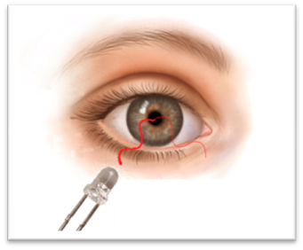
Figure 1. Depiction of eye regions of interest.
Though dissimilar from a microscopic cellular viewpoint, this is not of primary concern. Rather, interest lies in the clear color difference apparent in the three regions (mentioned above) that will have differing interactions with light. Just as we observed in Lab4, we expect a higher signal stemming from light directed to the pupil as compared to light directed toward the sclera. Nearly all the light directed toward the entrance pupil is absorbed. The white color of the eye reflects a majority of the light rays directed towards it. The ratio of light rays absorbed to reflected when directed to the iris depends on the eye color, with those eye colors darker in tone pigmentation yielding the higher signals.
Background Math
We note that the user’s focus is directed towards the Dell Monitor provided at each lab station in the Phillips 218 lab. At an estimated viewing distance of 20” (50.80cm), the Dell Monitor subtends 20.5 degree x 18 degrees of visual angle. Please use Figure 2 below for a visual depiction of this information [1].
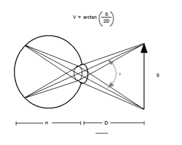
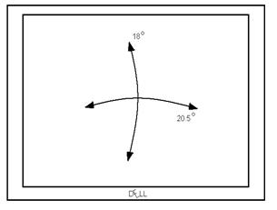
Figure 2. (Left) Background mathematics. Image influenced from Wikipedia discussion on Visual Angle.
Figure 3. (Right) Visual Angle subtended by ROI.
(Note: Ideally, it would be nice to map 2-dimensional gaze to one point on the monitor. Due to the uniformity that exists within the three regions of the eye listed previously, this is not entire possible with the setup we have implemented. (Please see Footnote [1].)
Logic Structure
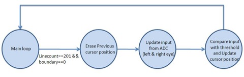
Figure 4. Top level view of software design.
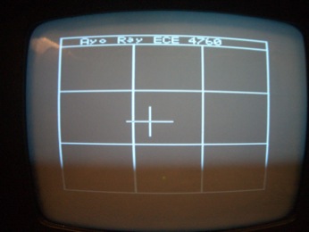
The main loop will update the contents of the frame on the TV screen and read the signals from the ADC while the MCU is not sending data to the screen (Linecount 231 to Linecount 30). It first prints a cursor on the center of the screen to indicate the reference level. Whenever the difference between the updated signal and the reference is above the threshold, the MCU will update the position of the cursor according to the direction of the eye movement it detected.
Expected Results
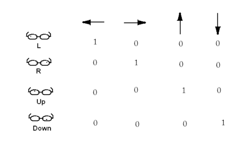
Figure 5. Diagram depicting Expected Results in one of four cardinal directions.
Our initial goal was to detect movement in two dimensions, as shown in Figure 5. The expected results from the emitter-phototransistor pair indicated in the left-most column are shown in each row, for particular gaze (indicated by top-most row). Results obtained confirm expectations seen in the first two rows of this figure. (Please see “Results” section below) [2].
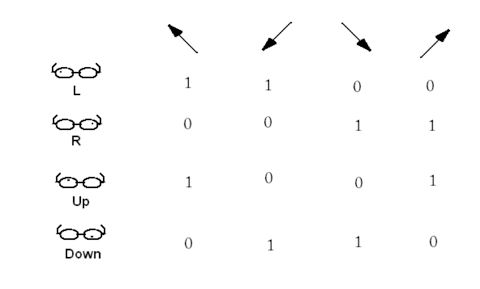
Figure 6. Diagram depicting Expected Results in one of four ordinal directions.
From these four cardinal detections, the next step would be to extend our detection into the ordinal directions. Figure 6 shows the expected results for gaze tracking in these ordinal directions.
Hardware/Software Tradeoffs
Real time eye/gaze tracking system is made possible with the incorporation of a CCD camera. The incorporation of a CCD camera adds an additional $20 expense to the budget. This is a significant addition in terms of budget costs. After some discussion, we decided that the incorporation of the CCD camera is well worth the cost. However, data collected from the CCD camera (i.e. frames of eye/gaze tracking footage) cannot be processed in real time with the Atmega 64 bit microcontroller. As such, we felt it more appropriate to use the emitter-phototransistor setup already being utilized. Though this is limiting, in the sense that one can only track eye movement in 8 directions (as opposed to “any” direction as would be the case with eye/gaze tracking with the CCD camera), there are benefits. As we have seen in Figure 5 (and Figure 6), our expected outcomes are much simpler in nature and much simpler to deal with. This simplicity helps to ensure that we have a device that responds to user input at near real time without adding too much strain on the microcontroller. This is a stepping stone that will serve the basis for future projects that will inevitably make improvements that strive for the goal of a "gaze tracking" system that can be achieved in real time with the resources used here or improved resources.
Standards
Safety. Given the nature of our backgrounds as biomedical engineers, our primary concern on any given project (health related or not) is safety. Specifically, is it safe to expose the eye to x amount of IR light over a finite amount of time, directed to the same area of soft tissue?
We first note that IR light is not visible light, but it resides after red light and opposite blue/ultraviolet light. It is known that a large percentage of IR light is transmitted through the skin (another type of soft tissue) [3]. The same result is expected for IR emission towards the eye. With ultraviolet light, however, the complete opposite is true. Blue light is absorbed by soft tissues and is known to cause damage to cells (specifically, damage to DNA). This is why the general populous is asked to be careful when exposed to sunlight for a long duration of time.
Freasier and Sliney have acknowledged that 0.3mW/cm2 is the maximum allowable intensity that the retina can be exposed to IR without damage. Being that our LTE-4208 device has a maximum aperture radiant incidence measure of 1.68mW/cm2, one must be careful in using this setup for long durations of time. [4] (Please see footnote).
National Television Systems Committee, NTSC. According to NTSC standards, television signal should contain information for starting a new frame, information for starting a new line, and information for brightness (white or black color pixel). As discussed in lecture, a long pulse (160--180 µs) near 0V is indicative of the start frame command. A short pulse (5 µs) near 0V is indicative of the start new line command. A voltage of 0.3V encodes a black pixel, a voltage of 1.1V encodes a white pixel, and in-between is grey [5] (please see Figure 7).
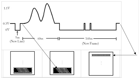
Figure 7. Diagram of video/sync signal coming from Port D.5 and D.6 of ATmega644. The 5µs pulse near 0V indicates the start of a new line. The lone 160 µs pulse with two intermediary spikes indicate the start of a new frame. (Technically, the bottom row of the left-most TV monitor image should be black pixels. To better display the idea of sync/video signal transmission, we have left it as white pixels. The next image (TV monitor in the center) shows the resulting brightness after the 60 us interval of video/sync signal information. The arrow here indicates that a new line has started.) (Further note that the new frame command could be in the range of 160—180µs)
Patents, copyrights, and trademarks which are relevant to your project.
Our project has been an attempt to think about the life of the future and to think of how technology can once again make people's lives easier. There are several methods being employed for gaze detection/tracking. These methodologies, though, make use of a CCD camera, at the very minimum. We distinguish ourselves, though, by attempting such a feat without the use of such a camera [6].
Program/Hardware Design
Hardware
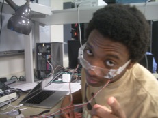
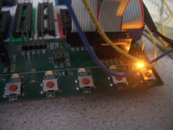
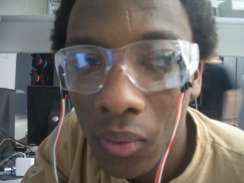
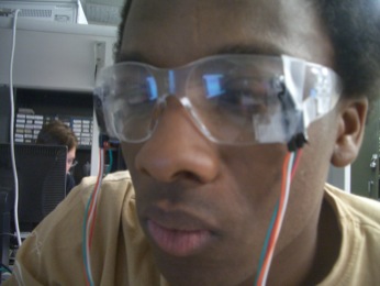
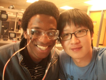
The hardware setup was quite simple. The hardware simply consisted of two pairs of emitter-phototransistor mounted atop goggles/glasses (in order to detect one-dimensional eye tracking). As noted before, the placement of these pairs is important [7]. Emitter-phototransistor pairs are placed off-axis so as to anticipate the arrival of the pupil upon the user shifting his/her gaze. The output signal stemming from the phototransistor is amplified for convenience. This way, it is easier to see the changes in signal brought about by different portions of the eye interacting with IR light. Amplification also makes it easier to set a threshold that will later be used for determining left vs right eye movement. The amplified signal is connected to Port A.0 and A.1, thus making use of the analog to digital (ADC) converter on the STK 500 board. Port B is jumpered to the LEDs as a means of visually displaying which direction the user is looking (i.e. toggling lights for a specific LED). This also served as a means for debugging. Lastly, we enabled hyperterm which was an invaluable addition to the hardware/software development process as it was continuously utilized for debugging and confirmation that things ought to be working the way that they were intended. (Assumption: User moves both eyes in the same direction at all times.)
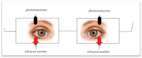
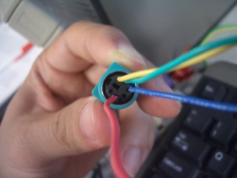
Figure 8. IR emitter-phototransistor pair.
Software
The software for this eye tracking system is in eyetrack.c, which can be found in the appendix. The functionality of the code can be broken up into two main sections. These include 1) converting signals from the two phototransistors and then 2) controlling the movements of the cursors on the TV monitor. First we use the ADC to get the voltage readings across the phototransistors, and the reference voltage is set to be at Vcc (5V). The ADLAR bit is set since we only need to use 8 out of the 10 bits, and the program reads the signals from PORTA.0 and PORTA.1 alternatively by toggling the last bit of the ADMUX. The readings are taken when the ADSC bit in ADCSRA is set to low, which indicates that the conversions are completed.
The display on the TV is similar to what we learned in Lab3. We set Timer1 to run at full speed and enable clear-on-match and turn on the compare match interrupt. The result is displayed from line 30 to line 200, and signals from the ADC are read during lines 201 to 29 (notice that Linecount is reset at Linecount =263).
Before we start the eye tracking system, we first need to get the reference signal from the eye when it is looking straight ahead. After turning on the power, the first 3 seconds are set as the initialization period. The data collected during this initialization period are discarded to eliminate noise. Then 180 sets of data (60 data per seconds) in the next 3 seconds after the initialization period are used as the reference (Leftref) for comparison later. We will average the signals every half second (save as Left_avg) and compare it with the corresponding reference signal (Leftref). If the difference between Left_avg and Leftref is greater than the threshold value, we will send a left signal and move the cursor to the left on the TV.
The threshold value for both eye are set to be 20. However, in our system, we are only able to get a very distinct difference for the left eye but not the right eye. Therefore, we normalize the signal from right eye by multiplying it by a factor of 3.
Results of the Design
Our optical tracking device performed very well. This device can be applied to many systems, or this device can be incorporated to other systems to add versatility to already existing devices/systems.
Preliminary tests were used to confirm that directionality can be detected. After mounting the left/right emitter-phototransistor pairs, we observed performance on the oscilloscopes provided in the Phillips 238 labs. The results of left vs right movement are shown below.
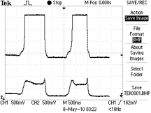
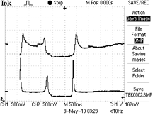
Figure 9. Caption: (Left) Baseline measure of off axis (i.e. emitter-phototransistor pair focused to the sclera) measure of reflection of IR light directed towards the user's eye. Upon looking left (top trace detecting left eye movement), voltage measured from the output of the op-amp escalates to 3.6 V (saturation value) which is 1.5V higher than baseline. A threshold value can then be used to confirm that the user has shifted his/her gaze towards the left. Note too, the trace detecting right eye movement (Trace #2, bottom trace) also changes voltage with leftward gaze. (Right) Baseline measure of off axis (i.e. emitter-phototransistor pair focused to the sclera) measure of reflection of IR light directed towards the user's eye. Upon looking right, voltage measured from the output of the op-amp escalates to 2.2 V which is 200 mV higher than baseline. A threshold value can then be used to confirm that the user has shifted his/her gaze towards the right. (See last sentence of “Software section for more details). Note too, the trace detecting left eye movement (Trace #1, top trace) also changes voltage with rightward gaze.
Further, tests were performed to see if there is a difference in voltage as a result of the emitter-phototransistor focused towards the user's iris versus the case when this pair is focused towards the user's pupil. In order to test this, commands of 'half-left', 'full-left', 'half-right', or 'full-right' (where 'half-left/right' was approximated to expose one's iris to the emitter-phototransistor pair, whereas the full-left/right exposed one's pupil towards the emitter-phototransistor pair) were given. The results are shown below. We note, however, that we opted not to use this information. However, we feel that this find is significant.
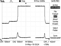
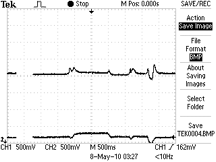
Figure 10: Figure showing Exposing emitter-phototransistor pair towards the iris versus exposing the emitter-photoranstor pair towards the pupil. Figure Caption: (Left) Looking left: The trace from the oscilloscope shows incremental steps indicative of the emitter-phototransistor pair directed towards different parts of the user's eye. Baseline indicates exposure towards the sclera. Exposure towards the iris results in a 200 mV increase of signal acquired. Exposure towards the pupil results in a 1.5V increase in signal (to saturation), much like before (please see Figure 9). (Right) Looking right: The trace from the oscilloscope shows incremental steps indicative of the emitter-phototransistor pair directed towards different parts of the user's eye. Baseline indicates exposure towards the sclera. Exposure towards the iris results in a negligible increase of signal acquired. Exposure towards the pupil results in a 100-200 mV increase in signal, much like before (please see Figure 9).
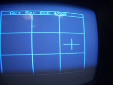
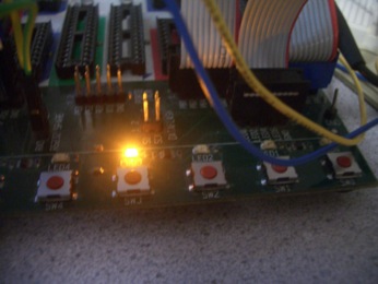
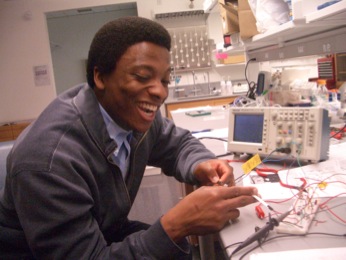
The accuracy of the device could be confirmed by two ways. Throughout the development phase, LEDs were used as a means to debug and to indicate user's gaze (please see images that follow this report). The other major component of this project was the eye tracking displayed on the TV monitor. The white cross (making up 1 out of the possible 3x3 boxes displayed) would change its position based user's gaze. In 5 trials of 10 eye movements, gaze tracking was correct 80%, 90%, 100%, 70%, and 90% of the time, respectively.
Safety is always of primary concern when dealing with a device that user's place on their bodies. As such, careful consideration was taken when mounting the emitter-photoransistor pairs onto the goggles. These parts have been mounted in a fashion that limits how far they protrude into the user's field of vision.
Conclusions
Our initial goal was to design an "Optical Mouse System" whereby a user could move a mouse cursor upon shifting gaze in one of the four cardinal directions. As was indicated in the logic diagrams shown above, it was our hope that 8 directional functionality (4 cardinal directions plus 4 ordinal directions) could be detected thus adding to the user experience. Based on what direction was detected, the cursor would move at a predefined rate. Due to difficulties encountered while interfacing the PS/2 connected mouse, we resorted to the design of an "Optical Tracking System" that proves that one can track gaze and that shows expected cursor movement.
The design was successful in that gaze could be tracked (albeit in one-dimension). The next step would be to mount the two additional emitter-phototransistor pairs to enable 2-dimensional tracking of eye gaze. We would further try once again to implement two-way signal transfer between the PS/2 mouse and the microcontroller. We would even consider interfacing USB, since it is the more recent and standard technology.
After demonstration, my partner and I discussed the applications that our final project lends itself to. There were three applications identified. 1) As already mentioned, it would be nice to carry this project further and change the position of a cursor based on eye movement. 2) One could play a game of tic-tac-toe with the device constructed. This game could be played against a friend, or against a computer with varying levels of difficulty. Though, we expect the "varying levels of difficulty" part to be difficult to write in software. 3) One could merge the concept here with Lab3: Video game. In addition to using pushbuttons for guiding movement, and a variable resistor to set the thrust, one could allow for the option for these inputs to be dictated by gaze. For instance, rightward gaze can be indicative of right tilt, leftward gaze can be indicative of left tilt, and upward gaze can be indicate the need for more thrust. The emitter-phototransistor pairs used for this must be very sensitive (i.e. electrical tape should be placed around these parts). Tests should be performed to ensure that this methodology for playing Lunar Lander is still enjoyable to the user.
Intellectual Property
Software written for this final project is based on code supplied for Lab3: Video game. The sample code provides a means by which TV signal is generated and the bitmaps necessary to display characters on the TV monitor.
For those who would like to take this project further and interface PS/2 mouse, we suggest taking a look at projects of yesteyears. Specifically, we recommend reading "Easy Input Head Controlled mouse and keyboard interface (2008)," "Accelerator Mouse (2005)," "Nintendo 64 to PS/2 mouse (2002)," and the last reference listed below. There are several other projects listed interfacing both PS/2 and USB that we haven't listed. One can easily scroll through the list with "Ctrl+F" "mouse" search on the "Final Projects" page of the ECE 4760 webpage.
Ethical and Legal Considerations
As up and coming engineers, we fully abide and adhere to the ethical standards set forth by the IEEE, NSPE (National Society of Professional Engineers), and the Biomedical Engineering Society (BMES).
Specifically, all the work performed, here, is done to better people’s lives in a safe and responsible manner. All the claims made in this report are honest, to the best of our knowledge. Undertaking such a project has lead to a deeper understanding of the previous technologies and potential applications.
Throughout our work, class members were kind enough to offer suggestions when hurdles were encountered. To those individuals, we say a “thank you.” We, too, tried to offer sound tokens of advice when we could.
All in all, our work is meant “to increase the competence, prestige, and honor of the” engineering profession(s).
We understand that ethics is the guiding principle by which engineers (and anyone skilled at a particular trade) are able to stay true to their role within society. We believe that the ethically inclined society is a safer society. Our work both in the past, the present, and the future will be done to keep this going.
We do not intend to sell our product in the market so there are no legal considerations. If we did, then product safety must be considered.
Footnotes
[1] Our initial thought was that by detecting pupil/eye movement in one of four cardinal directions, a contrived “Optical Mouse System” would enable users to move a mouse cursor with 8 directional movement. The implementation of this initial project was thought to serve a twofold purpose: 1) Enable user(s) suffering from paralysis to still use a computer (the same argument is used for those users suffering from severe muscular and/or joint pain such as carpel tunnel), 2) Add to the overall enjoyment experience by computer users. This is discussed further, later in the report.
[2] Though there is cross talk between IR emitter-photransistor pairs, this is expected. This issue is addressed in the “Software” section of this report.
[3]Simple experiments conducted with a red laser pointer and a green pointer directed toward the tip of one’s index finger show that red light readily gets transmitted through soft tissues. The percentage of transmittance is even larger for infrared light.
[4] The data sheet for the LTE-4208 provides sufficient information to calculate expected “aperture radiant incidence” measures, with the test conditions, provided. We should have recorded the voltage on the long leg of the emitter to provide an accurate measure of the intensity our system exposes to one’s cornea.
[5] In this project, we did not encode voltages between 0.3V and 1.1V to be gray pixels. Rather, we simply used white and black pixel intensities defined by 0.3V and 1.1V, respectively.
[6] As mentioned earlier, our initial goal was to devise an “Optical Mouse System” by which a user can move a mouse cursor via eye movement. To this end, we have not come across any patents attempting such a feat. However, it would not come as a surprise to learn that such an enterprise is already in existence.
[7] The angle at which the IR-emitter points towards the eye is also very important. Differences in this angle between the left/right eye yields different detection signals as is apparent in the “Results” section.
Schematic
- (i) Schematic of video signal.
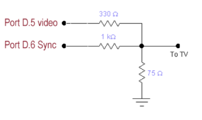
Figure 11. Schematic of TV connection taken from ECE 4760 website. http://courses.cit.cornell.edu/ee476/labs/s2010/lab3.html
- (ii) Schematic of phototransistor-emitter pair, op-amp, ADC connection.
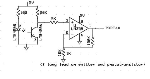
Figure 12. Schematic of emitter-phototransistor pair connected to ADC of STK 500 board Modified image taken from ECE 5030 website. http://instruct1.cit.cornell.edu/courses/ece5030/labs/f2009/Plethysmograph.html
Parts List
| Parts | Source | Quantity | Unit Cost | Total |
| STK500 | ECE 4760 Lab | 1 | $15.00 | $15.00 |
| ATMega644 | ECE 4760 Lab | 1 | $8.00 | $8.00 |
| Op-Amps | ECE 4760 Lab | 2 | $0 | $0 |
| Safety Goggle | Previous Owned | 1 | $0 | $0 |
| IR Emitter | ECE 4760 Lab | 2 | $0.25 | $0.50 |
| Phototransistor | ECE 4760 Lab | 2 | $0.54 | $1.08 |
| Resistors & Capacitors | ECE 4760 Lab | -- | -- | $0 |
| Total | $24.58 |
Tasks
All tasks were done together, as we have found that this greatly helps with the learning process.
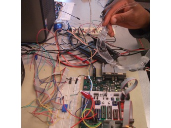
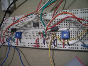
Photos

Appendix: Commented Programming List
References
ATmega64 datasheet
Morimoto, et al. Pupil Detection and tracking using multiple light sources.Image and Vision Computing. 18 (2000): 331--335.
Voronka et al. US Patent #6299308. Low cost non imaging eye tracker system for computer control.
Sliney and Freasier. Evaluation of Optical Radiation Hazards. Applied Optics. January 1973. Vol. 12 (1).
http://www.eyetracker-drvoss.com/Safety_Infrared-Radiation.html
http://www.computer-engineering.org/ps2mouse/
IEEE Code of Ethics
Thanks
We would like to thank two individuals that helped us to complete this project. These individuals are Prof. Bruce Land, and TA Tim Sams.
Enough cannot be said about Prof. Bruce Land and his devotion to his students. Specifically, we thank you for your helpful suggestions throughout the project development process. We also thank you for helping to ease our panic in the days leading up to demonstration. We both feel privileged to have taken your course. Both of us highly recommend this course, or ECE 5030: Bioinstrumentation, to anyone who has a desire to learn more about the role electronics plays in the grand scheme of the engineering disciplines.
Simply stated, Tim Sams has been a very helpful and sincere TA, throughout the course. Tim, we thank you for being there to guide us through the increasingly difficult lab modules. We also thank you for asking us questions that led to progressively successful lab demonstrations.