ECE 4760 Final Project Report: Grapefruit Segmenter[A] [A]A PDF version of this report is available here
May 9, 2011
Kevin Martin <ksm76> Hyundo Reiner <hpr6>
Grapefruits are delicious, but a hassle to eat.[B]
[B]That is, xkcd author Randall Monroe is only half right
To address this problem, we developed an automated grapefruit segmenter that detects pulp edges in halves of grapefruit and slices around them, enabling the user to extract the pulp without tedious manual cutting.
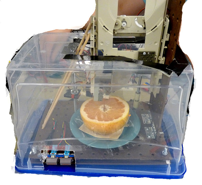
What? The device, about the size of a breadbox, consists of a rotating platform on which the fruit hemisphere is placed, a set of knives attached to a stripped down CD-ROM tray, and a flex sensor attached to a cantilever assembly built from modified LEGO® bricks. The system is controlled by an Atmel ATMega644 Microcontroller Unit (MCU) running an AVR GCC program.
Why? The goals are twofold: First, to attack a completely novel problem we were both passionate about while building a tool that could, ideally, be a welcome addition to daily life. Second, we wanted to overengineer something and get away with it.
Table of Contents
Part I. High Level Design
1 Rationale and Problem Overview
As regular grapefruit consumers, both of us could appreciate the value in automating the cutting procedure. We saw the problem as suitable for a final project because it is [very] challenging while requiring a combination of software, analog electrical hardware, and physical components. The device has further appeal as something that can even be commercialized if it works well enough.
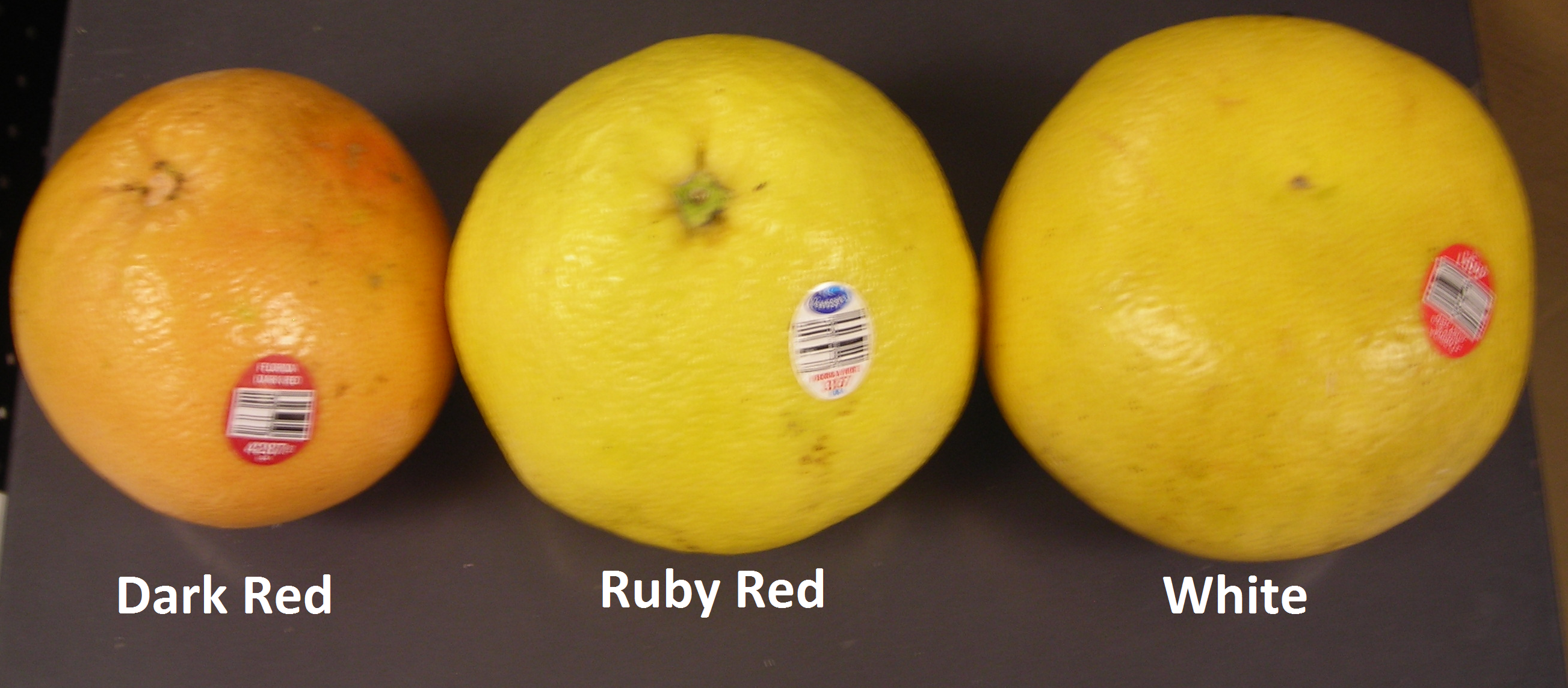
But challenges abound. For most humans, the task of cutting out segments in a grapefruit is simple. We have a substantial amount of dexterity along with direct feedback that enables us to cut around the pulp of a grapefruit with relative ease. However, an automated machine is much less capable, especially one which is constructed under a limited budget. The main challenge is trying to account for the large variability present from one grapefruit to another. We hoped to be able to cut many different types of grapefruit, including ruby red, white, and dark red varieties, as shown in Fig. 2↓; including multiple varieties causes more problems in variability. Furthermore, no physical dimension of a grapefruit is guaranteed: the widths of the segments typically vary by a factor of at least two; the radial length of segments can be different, even within a fruit, and not perfectly straight; the strength of the pulp and edges depends specifically on the fruit; the rind has variable width; the height and width of a grapefruit varies, especially between species; there are usually seeds that knives must avoid, and so on. We tried to address all these problems and construct as robust a machine as we could, though obviously there will be cases where automatic segmenting is either inefficient or, at worst, impractical.
2 Background Math
Formal analysis of the geometry of the problem is intractable due to the large variation in grapefruit physical characteristics and lack of standardized studies on such quantities. Thus, we were unable to base our design on any sort of idealized grapefruit model, and most of our dimensions and quantities resulted from trial and error, including all the dimensions of the apparatus, the motor drive voltage, and the position of the knives on the CD tray.
It can be reasoned that the optimal solution to the problem of finding edges in the fruit would reduce to a Kalman Filter applied to either flex sensor or image data, that combined a model of grapefruit segment placement as well as the response of the sensor to the fruit. This would be an extremely complicated approach, and its behavior would depend on how well the process and measurement noises could be characterized. Dismissing this tool, the algorithms we implemented achieved, in some cases, impressive results.
Other math needed in the project is trivial, such as precalculating the gain of the amplifier in Sec. 6.3.2↓.
3 Logical Structure
3.1 Software
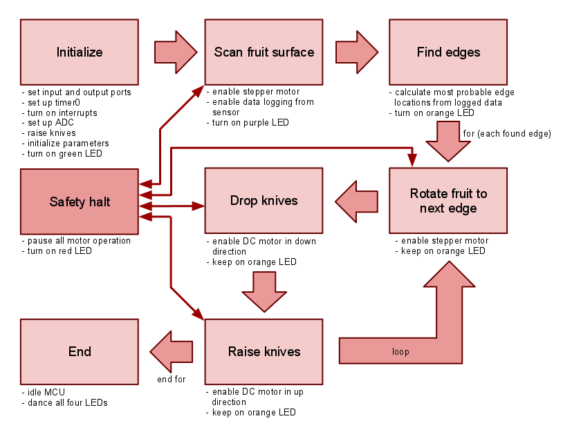
The overall software flow diagram is shown in Fig. 3↓. The software had a few specific tasks at a given time, depending on what part of the process the machine was executing. Its main responsibilities were handling user input, controlling the stepper motor during the data collection phase, logging and processing sensor data, and controlling the stepper and DC motors when cutting. Since the design only requires a few steps to be done sequentially, the software was straightforward compared to that of previous labs (e.g. the video game). For more detail on the specific implementation of each task, see Sec. 7↓.
3.2 Hardware
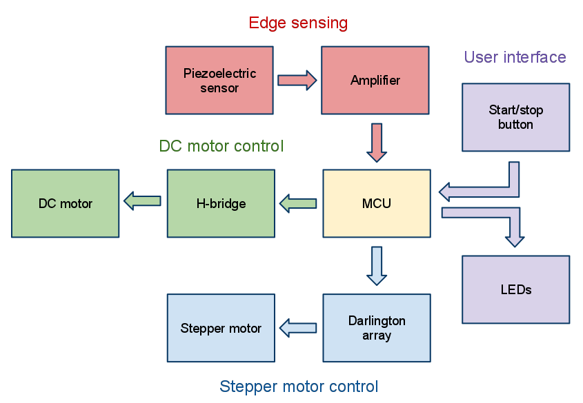
There are independent circuits for the flex sensor, stepper motor control, DC motor control, and user interface. See Sec. 6↓ for more detail on each of these.
During typical operation of the machine, the user must hit the “Start/Stop” button to initiate the cutting sequence after power up. The MCU begins rotating the grapefruit around its center axis by commanding the internal electromagnetic components of the stepper motor, which is driven by the MCU via a Darlington array. As the fruit is rotating, the carefully-supported piezoelectric flex sensor deflects off the edges of the grapefruit. The sensor transduces the small mechanical deflections into measurable electrical signals,[C]
[C]For the principles of piezoelectric sensor operation, consult Wikipedia
which are amplified by a non-inverting op-amp amplifier, then fed into the ATMega644’s analog to digital converters (ADC) with an adjustable threshold, producing a time history of how the sensor position changed as it was dragged across the fruit. Because we need to know the angular displacement of the fruit at all times, and because we need to start and stop rotation instantaneously, the stepper motor, with its discrete driveshaft positions, was the obvious choice for the task of rotating the fruit.
Once the sensor has traversed the fruit, the MCU halts the stepper motor and calculates the best estimate for all the edge locations. Then the MCU controls the DC motor on the CD-ROM tray and the stepper motor simultaneously to rotate to the next estimated edge location, drop the cutting knives, and raise the cutting knives, until all found edges are accounted for. An H-bridge controls the DC motor, allowing the MCU to drive the CD tray up and down (as well as at much higher voltage and current than the MCU can supply). At any point in the operation, the user can hit the “Stop/Start” button to pause the machine. Status LEDs indicate the current step in the process that is executing, including when safety checks have failed. The basic flow of the hardware is illustrated in Fig. 4↓.
4 Hardware/Software Tradeoffs
Our design allows for computationally cheap operation by doing much of the necessary work in hardware. Our original design involved using a camera to detect edges, as described in Sec. 8.1↓. This would have been extremely intensive in terms of both computation power and memory requirements, because each (possibly color) frame would have to be read in to the MCU and digitally processed before letting the stepper advance the fruit position. Instead, using a force sensor mounted on a cantilever is an elegant solution to finding the edges of the fruit: not only does it reduce the amount of information to process per edge, but it also allows us to process the signal partially in hardware. Initially, we didn’t even use the ADC, opting to tradeoff software complexity for very slight hardware complexity, namely a comparator. The stepper motor positions (hereafter referred to simply as “steps”) where the comparator transitioned from logic low to logic high were saved in an array, and we ran it through our own simple edge finding algorithm to deduce the most likely edge locations from a sparse set of data (see Sec. 7.4↓). Ultimately, we redesigned the edge detection algorithm to use the ADC, undoing this tradeoff.
Another design consideration was to use as few motors as possible without losing accuracy or robustness in operation. We tried to implement as many things as possible in mechanical hardware, so that we could forgo extra control logic on the MCU. In this spirit, we chose not to have separate motors drive the exact radial position of the knives, the rotation of the “back” or “rind” knives, or the sensor height. The minimum number of motors we found could was two: one for rotating the fruit and one for raising and lowering the knives. We decided that the accuracy possible using a fixed radial position would be sufficient, given that the variation in grapefruit diameter is not too extreme. The fact that stepper motors can be run without any extra sensors or control (open-loop) simplifies software substantially, as we won’t need to implement any sort of closed-loop rotation measurement and PID control as in the tachometer and motor control lab (Lab 4).
To control the DC motor that powers the cutting knives, we could either use pulse-width modulation (PWM) of a fixed voltage to vary the supply power, or we could simply use a constant voltage. The former approach is very flexible, allowing effective motor speed to be adjusted via software. However, it also requires non-trivial closed-loop control for best operation. Since we have access to a variable power supply in lab, and various diodes to perform any crude voltage regulation if needed, we decided to only use a constant drive signal, relying on empirically derived timings to change the motor state. In addition, we had to come up with mechanical ways to control the parallel edge-cutting knives with the circumferential rind-cutting knives with the same motor. For a full description of the physical design, see Sec. 6.4↓.
Lastly, having a simple user interface is important because it means having less complicated hardware and software. Because our device is built to perform one function only, we could reduce the user interface to a two-button panel. Instead of a more expensive and inefficient LCD readout, we installed four LEDs for status indication. The extra work was worth the improvement in the user experience.
5 Existing Patents, Copyrights, and Trademarks
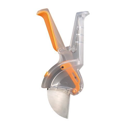
As far as we can tell, there are currently no automated grapefruit cutters commercially available, though several hand-operated gadgets exist. A portion of our design idea did come from the Chef'n Grapefruiter(tm), a manually operated grapefruit sectioning tool pictured in Fig. 5↓. However, on top of being fully automated, our design seeks to cut out segments that are of variable width instead of having a set distance between blades as in the Grapefruiter and all solutions we found on the market.
Part II. Program and Hardware Design
6 Hardware Details
6.1 DC Motor Circuit
More Info
As put forth in Lab 4, it is always a good idea to isolate logic power from motor power to avoid excessive noise induced from a DC fan (especially one with brushes) or current dips as the motor(s) strain. The main slicing knives are mounted onto a heavily modified CD tray scavenged from an old desktop PC. Fortunately, after stripping it down to the bare essential components needed for this design, we saw that the tray was powered by a simple DC motor with a complex, but robust mesh of gears. Pre-assembly testing revealed that the motor+tray apparatus can handle well over 5V, and provides a very strong push at 9-12V without noticeable strain in any of the components. In fact, testing revealed that the 5V the motor typically runs off of is insufficient cut the grapefruit, so we had to up the motor power to a full 12V, drawn from a regulated 12 V rail from the power supply unit (PSU) scavenged from an old computer (for more see Sec. 6.4↓).
As put forth in Lab 4, it is always a good idea to isolate logic power from motor power to avoid excessive noise induced from a DC fan (especially one with brushes) or current dips as the motor(s) strain. The main slicing knives are mounted onto a heavily modified CD tray scavenged from an old desktop PC. Fortunately, after stripping it down to the bare essential components needed for this design, we saw that the tray was powered by a simple DC motor with a complex, but robust mesh of gears. Pre-assembly testing revealed that the motor+tray apparatus can handle well over 5V, and provides a very strong push at 9-12V without noticeable strain in any of the components. In fact, testing revealed that the 5V the motor typically runs off of is insufficient cut the grapefruit, so we had to up the motor power to a full 12V, drawn from a regulated 12 V rail from the power supply unit (PSU) scavenged from an old computer (for more see Sec. 6.4↓).
In order to move the tray from software, we needed to connect a high-voltage, relatively high-current power supply in one of two polarizations across the motor leads to get it to extend or retract. An H-bridge circuit, shown as a simplified set of switches in Fig. 7↓ does just this. It is a simple set of four switches--usually transistors--that engage in one of two patterns to apply a voltage in either direction across a DC motor, thereby turning the driveshaft in both directions. The circuit can also attempt to brake the motor by shorting the two terminals to VM or ground. One must also be careful when controlling these switches from software, since it is easy to cause a short circuit by turning on either a top and bottom switch on either side.

Figure 7 Operation of basic H Bridge circuit. By Cyril BUTTAY (own work, made using inkscape) [GFDL, CC-BY-SA-3.0, or CC-BY-SA-2.5-2.0-1.0], via Wikimedia Commons.
The implementation of the H bridge can prevent this. While we can build an H-bridge with components commonly available in lab, H-bridge ICs offer a more robust solution with short-circuit protection, level shifting (in case motor and logic voltages are different, as they are in ours), a high range of voltage operation, and high current output. Based on I/O and package requirements, we opted for a Freescale MPC17510, in a small-but-solderable 24-pin TSSOP package. The IC takes as input three signals from the MCU: an enable toggle EN, and two pins IN1 and IN2 to determine polarity applied to the motor. Setting these latter two pins to (HI, LO) biases the motor one way, while (LO, HI) biases it the other. The circuit handles all other combinations of EN, IN1, and IN2 without short circuiting. Two outputs of the IC go to the motor leads, and several other pins are connected with capacitors to act as charge pumps for the level shifters (not related to actual operation of the H-bridge; used for going from logic level to transistor-driving levels). We have discussed here only the crucial operational components of the particular chip; see the datasheet, available in Sec. 17↓, for much more detail and explanation for all the extra pins that seem to complicate a simple circuit.
6.2 Stepper Motor Circuit
More Info
Other steppers, namely bipolar motors, have only four leads, while higher phase-count motors have even more. Six-lead is a common arrangement, and allows for simpler, unipolar drive circuitry by having a center tap on each coil to make reversing current direction easy. A stepper motor can’t be driven with a simple constant DC or PWM signal — it has six input wires (see sidebar) that all need to be set appropriately in order to energize electromagnets that cause a central permanent magnet to spin. The magnet is the shaft, and by pulsing current down the coils of the electromagnets in the proper sequence, we can pull the magnet around in discrete steps. Fig. 8↓ shows an animated mock stepper motor as its internal magnets turn on sequentially to attract different teeth and cause the shaft to spin.
Other steppers, namely bipolar motors, have only four leads, while higher phase-count motors have even more. Six-lead is a common arrangement, and allows for simpler, unipolar drive circuitry by having a center tap on each coil to make reversing current direction easy. A stepper motor can’t be driven with a simple constant DC or PWM signal — it has six input wires (see sidebar) that all need to be set appropriately in order to energize electromagnets that cause a central permanent magnet to spin. The magnet is the shaft, and by pulsing current down the coils of the electromagnets in the proper sequence, we can pull the magnet around in discrete steps. Fig. 8↓ shows an animated mock stepper motor as its internal magnets turn on sequentially to attract different teeth and cause the shaft to spin.
Figure 8 Physical Operation of Stepper Motor. (By Wapcaplet; Teravolt.Teravolt at en.wikipedia [GFDL], via Wikimedia Commons)
There are many different types of stepper motor, as well as different winding arrangements, which determine how the magnets shown above are controlled. The motor used in our design, an Aratron AB model PF35T-48, is unipolar, two coil model.
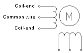 The internal wiring corresponds to the idealized model shown in Fig. 9↑.
Figure 9 2-phase unipolar stepper motor internal coils and wiring.
(By Yegorius (Own work) [GFDL or CC-BY-SA-3.0-2.5-2.0-1.0], via Wikimedia Commons.)
(By Yegorius (Own work) [GFDL or CC-BY-SA-3.0-2.5-2.0-1.0], via Wikimedia Commons.)
The two common wires are shorted and go to motor power, while the other four go to the outputs of a Darlington array. The Darlington array chip (ULN2003AN) contains seven pairs of transistors arranged in a Darlington configuration (Fig. 10↓)
, which act as input current amplifiers, in this case of the four control signals from the MCU going to the four different coil taps. By alternating which of the coil-end wires is ground, the direction of current and thus orientation of magnet poles can be changed.

There are also several stepper drive patterns that result in different motor torques and angular resolution. Since our stepper motor is mating to a large-diameter gear, a relatively large step on a small motor shaft radius maps to a much smaller angular step on the gear that holds the grapefruit. Thus we chose to use a high-torque full step drive pattern that has two phases energized at a time, as opposed to the one-at-a-time example of Fig. 8↑. The step sequence is stored in software as a 2D array look-up table; the MCU sets the output ports to the appropriate value based on what the integer step index is. For smoother operation, the ideal drive patterns are sines and cosines, phased appropriately. This would require a look-up table and D to A converter, complicating our design unnecessarily. The vibration from the motor is significant, but it does not affect the quality of measurements or cuts, and we significantly reduced the noise by adding padding around the edges of the platform to dampen the vibrations.
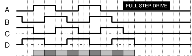
Figure 11 Full Step drive pattern, where A and C are the two coil-ends of one phase, and B and D are the ends of the other. (By Misan2010 (Own work) [CC-BY-3.0], via Wikimedia Commons)
6.3 Sensor Circuit
Our sensor circuit can be divided into two main, sequential parts: the piezoelectric sensor that’s attached to the fruit probe and an analog amplifier.
6.3.1 Piezoelectric sensor
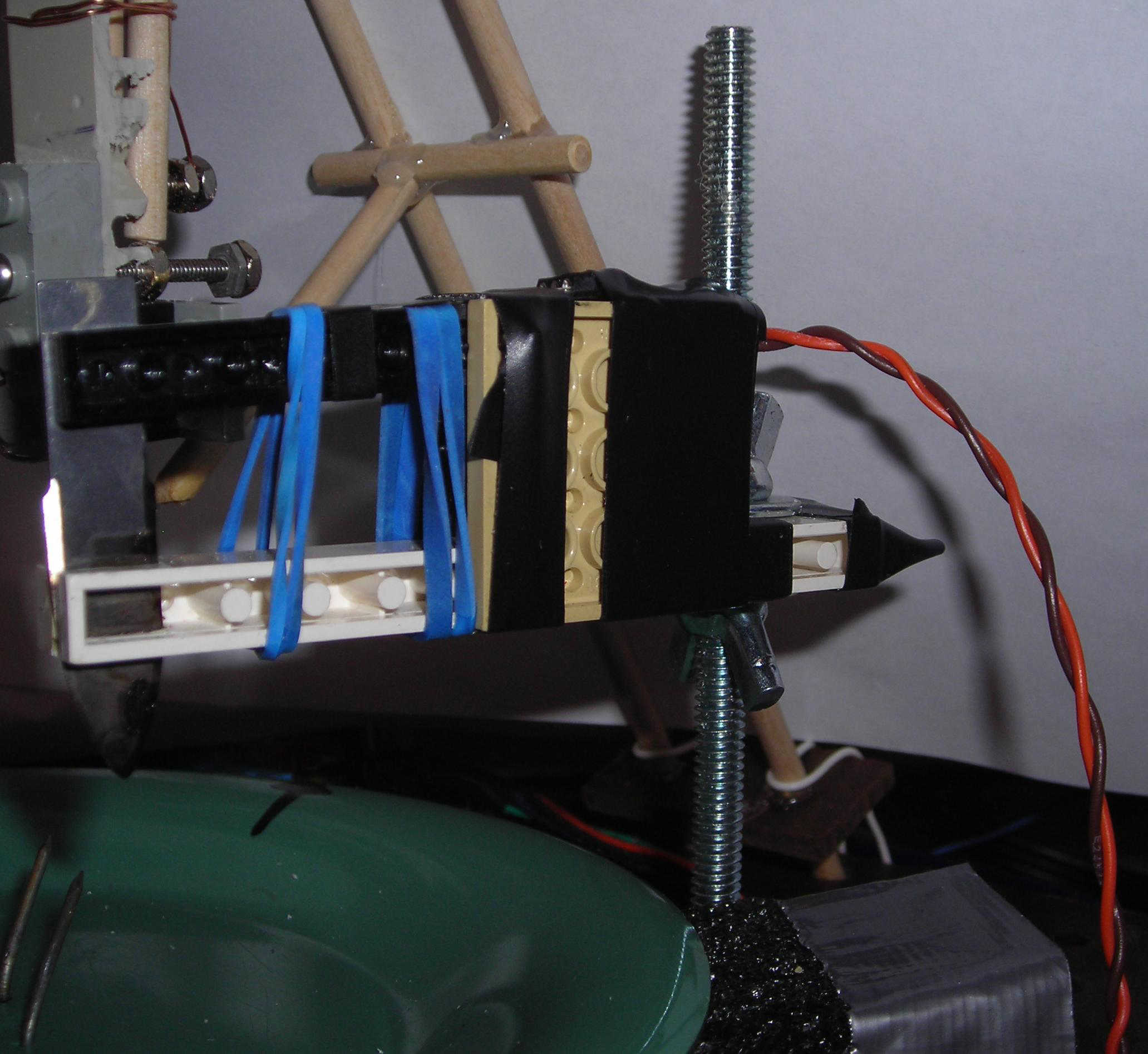
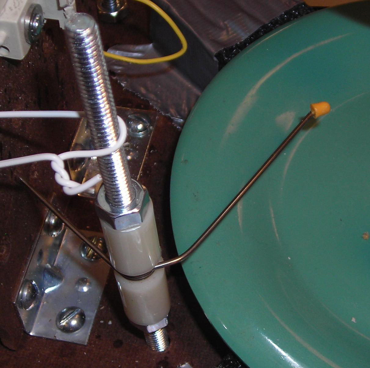
The sensor we used was an extremely sensitive, LDT0-028K laminated piezoelectric film vibration sensor. We mounted it on a cantilever apparatus, as shown in Fig. 12↓, which was constructed out of LEGO® bricks. A dulled X-Acto© blade is attached to the end of the cantilever, so that when the device is positioned above a rotating grapefruit half, with the point of the blade submerged in the flesh by about 4 mm, the blade point would be able to ride along the surface, transferring the up and down motion down to the axis of the cantilever, on which the sensor is placed.
6.3.2 Amplifier and Analog to Digital Converter
When testing with real grapefruit, we found that our sensor was able to produce voltage spikes on the order of 20-200 mV after hitting an edge. In order for the MCU to interpret these reliably, we chose to amplify the signal substantially. We used an operational amplifier on the LM358 chip to create a single stage non-inverting amplifier (with topology shown in the schematic of Fig.25↓, as well as this thorough Wikipedia page). The gain of the amplifier was
Moreover, we felt more comfortable operating the ADC with a much larger amplitude range, especially since our bit depth is “only” 8 and we aren’t bothering with ADC noise cancellation.
VoutVin = (1 + R2R1) = 101,
More InfoMoreover, we felt more comfortable operating the ADC with a much larger amplitude range, especially since our bit depth is “only” 8 and we aren’t bothering with ADC noise cancellation.
which increased the sensor output to a maximum of 5 V, at which it has been clipped. This amplified signal is then fed into a single channel of the MCU’s on-board analog to digital converter (ADC). The configuration of the ADC is discussed more in the relevant software section, but in order for the physical ADC to assign discrete values to input voltages, it needs a reference voltage. This can be the 2.5V band-gap reference voltage available internally, a 1.1V internal reference, or whatever value is supplied on the AREF pin of the MCU. We ran VCC through a 10K pot back to MCU ground, put a large cap on the wiper of the pot to smooth potential voltage fluctuations for a maximally stable reference, and set the AREF value manually after measuring a few runs of the sensor output on an oscilloscope. This lets us change the levels easily as we change other parts of the design.
Why did we bother to amplify the signal instead of just setting a suitably low VREF for the ADC? In order to get more accurate quantization, it’s important to set VREF to retain as much dynamic range as possible while clipping only the inputs that add no extra information. Simply put, it’s hard to tune a reference voltage down to a few tens of millivolts with accuracy using only a pot--multimeters can only offer so much accuracy.
In the final implementation, this parameter is fixed; were this a commercial product, the user would not be expected to tweak such a parameter with no a priori knowledge of the machinations of the device and how it reacts to different types of grapefruit.
We also found through extensive testing that it’s best to amplify a certain lead of the sensor over another. The flicks that occur when the probe drops from an edge back down to the flesh are much sharper in time and higher in amplitude than the comparatively smaller magnitude “humps” of output when the sensor knife first rides up an edge. Before attempting an ADC solution, we checked the duration of these flicks. Since we’re only sampling at a relatively slow 390 Hz (Ts = 2.56 ms), these pulses must be large enough to ensure that we capture them. Fortunately, they are on the order of 5-10 ms wide so such a low rate is acceptable.
6.4 Physical Construction
Most of the parts for the physical structure were purchased from Lowe’s or created from various parts that we already owned. The main aspects of the physical construction are the base and supports, the rotating platform, the force sensor mount, the CD tray actuator, and the safety enclosure.
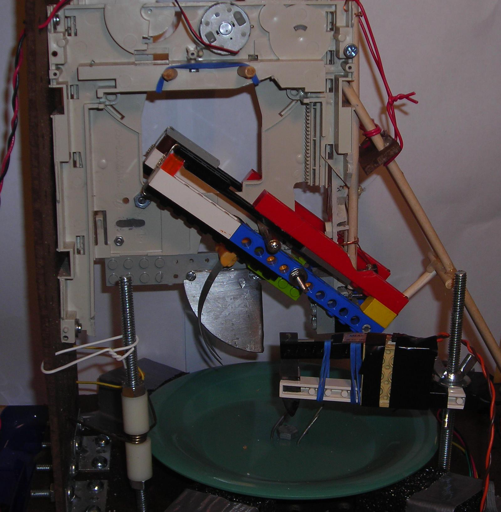
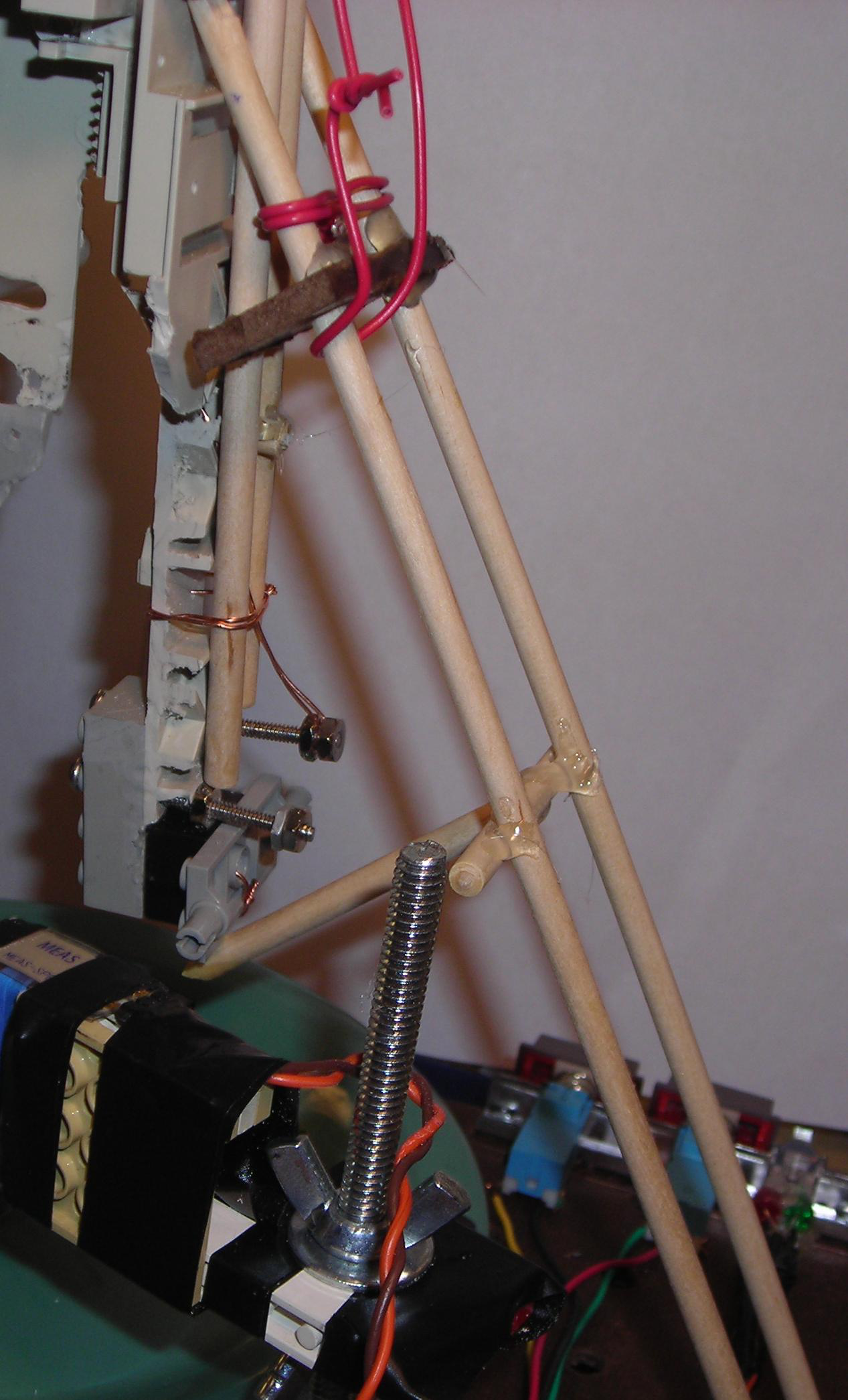
The overall physical design is shown in Fig. 13↓. We constructed the base of the apparatus out of two parallel sheets of Masonite pegboard with 1/4” holes, between which we sandwiched the stepper motor so that the gear of the motor was protruding from the top piece. We attached a vertical piece of pegboard to the base as a support for the CD tray. A long 1/4” diameter bolt through the base acts as a variable height stand for the sensor, which could be adjusted easily by moving the wing nuts holding the sensor in place up or down. We also extended two thin dowels from the base to the unsupported side of the CD tray to act as further support and stabilize the motion of the knives, with further wire and dowels to provide rigidity to the system, shown in Fig. 14↓. Last, we mounted a torsion spring on a 1/4” bolt between the CD tray pegboard support and the fruit to keep the fruit from shifting while knives were cutting, shown in Fig. 15↓.
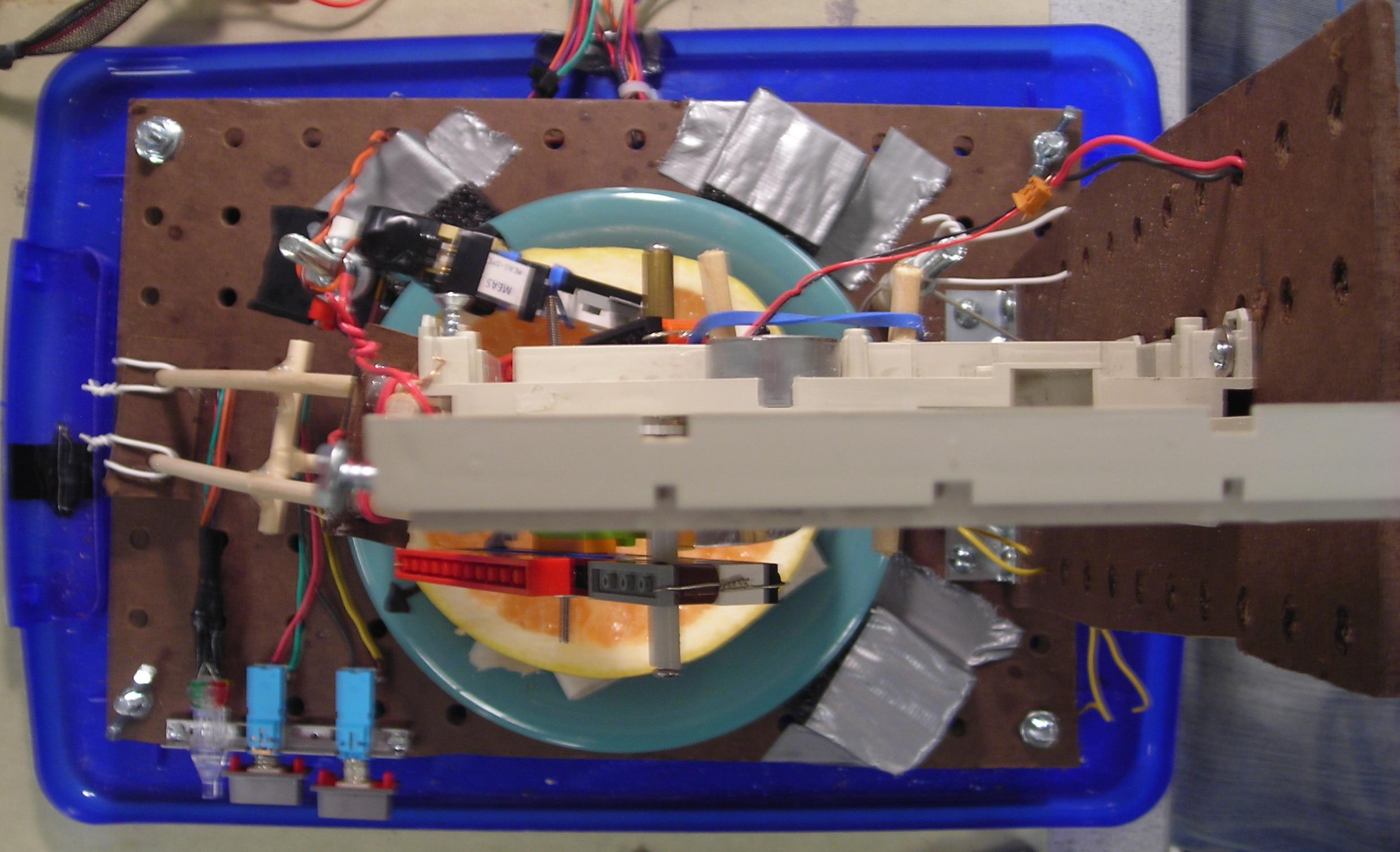
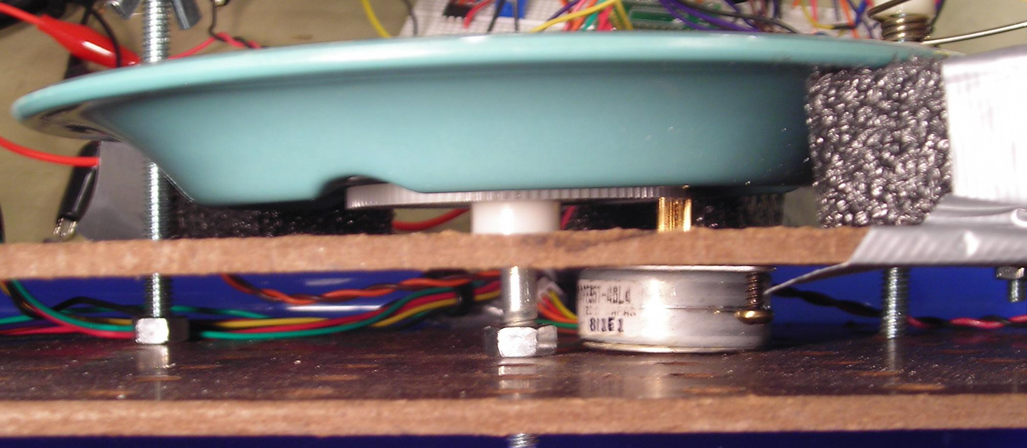
The rotating platform shown in Fig. 16↓consisted of a 2.25” diameter gear rotating on a 1/4” bolt positioned so that it meshed with the gear of the stepper motor. The relatively large gear size compared to the stepper motor gear allowed us to control the position of the plate in much smaller increments than a single step size for a motor could provide, resulting in much more precise positioning; See Sec. 7.2↓ for the full details. On this we fastened a hard plastic plate so that the plate and gear would rotate together about the bolt. Four small nails near the center of the plate, anchor the grapefruit to the plate.
The force sensor mount that we constructed is mentioned in Sec. 6.3↑.
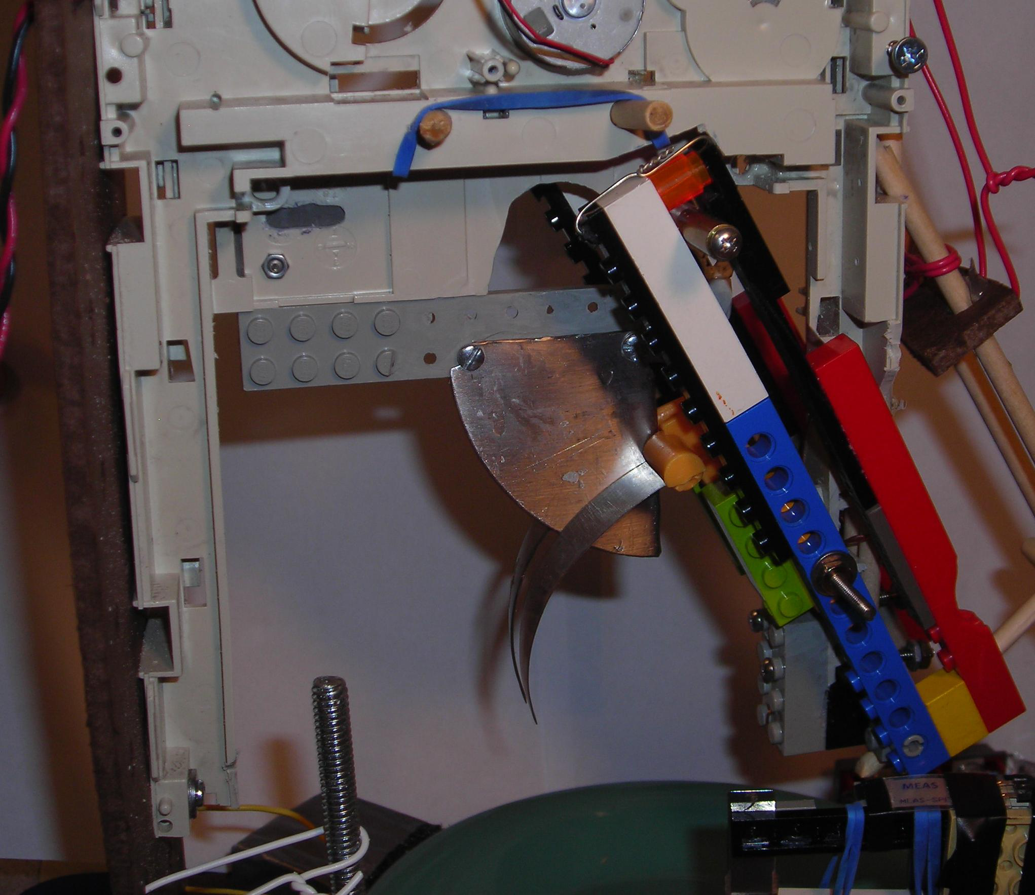
We mounted the CD tray vertically and used its DC motor as a linear actuator to propel the knives up and down into the fruit. The motor was already equipped with a gear system, meshed to a toothed tray riding on plastic rails. In order to implement the rotating knives that cut around the rind, two rectangular grooved plastic pieces made of LEGO® bricks were mounted to an axis at the base of the CD tray; these are shown in detail in Fig. 17↓. A bolt extending on both sides of the CD tray rides in grooves cutout in the knife arms. When the tray moves up and down, this bolt slides in the groove, causing a rotational motion about the pivot point on the corner of the CD tray. Both the parallel knives and the rind knives are detachable so that they can be easily cleaned.
Because safety was a large concern for the project, we constructed an enclosure out of a plastic bin to shield the user from the dangerous parts of the device. The device is built on top of the underside of the lid, and the user has to place the bin over the lid to seal it, actuating a switch to ensure the cover is on tight before beginning operation, as shown in Fig. 18↓. We enforced this safety feature by connecting two separate leads to the underside of the lid, stripping off a large portion at the endpoints, and running it through the handle. A separate wire runs from one edge of the bin, around the outer lip, and to the other edge of the bin such that having the bin placed on the device short the two exposed lead ends attached to the lid (see Fig. 19↓). Safety is discussed in more detail in Sec. 11↓.
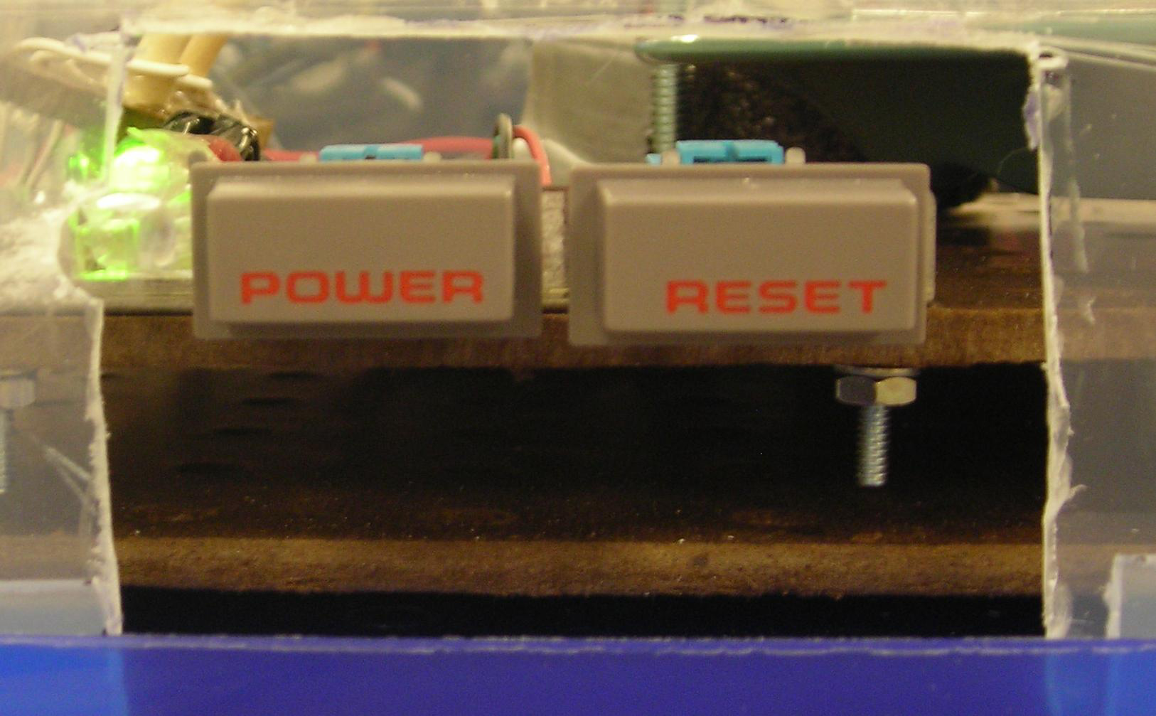
6.5 User Interface
As shown in Fig. 6.5↑, the user interface is extremely simple. There exists just a power switch and a momentary, normally open start/stop button, taken from an old NES system, and four LEDs. The power button is directly wired to the MCU host board power switch. The stop/start button is handled by the software to halt and resume either motor during operation, and is debounced; see Sec. 7.1↓ for more details. The four LEDs indicate the status of the machine during operation: green means the machine initialized properly and is waiting for the user to start the process, purple means the machine is scanning the surface for edges, orange means the machine is cutting out found edges, and red means the external enclosure is loose, and must be secured before operation may resume. When the machine is done, it flashes all the LEDs one at a time.
7 Program Details
There are many ways to implement the system as described in high-level form. We’ve implemented a relatively small program that uses only one 8-bit counter triggering one ISR that manages the button debouncing, stepper control, DC motor control, and ADC storage and triggering all in one. The interrupt rate is the least-common factor of all the time intervals we care about, and this master tick is then scaled down via modulo operators to control other items slower. Most of the time-sensitive algorithm is expressed in Algorithm 1↓, and the following sections will refer heavily to it. All the logic is possible because of a comparatively slow millisecond-order master pulse.
On top of this is the function that analyzes the raw data to estimate edge locations. This does not interact in any way with hardware, and has no realtime constraints.
if logEdges and done pre-cutting
-
accumulate ADC data for this step
initiate another ADC conversion
end

if ticks mod 8 == 0
-
// Handle motors at slower rate than ADC logging
if stepperEnableFlag
-
increment step count, take mod 4 for new index in 0..3 for the next drive pattern
lookup set of outputs based on index
send appropriate logic signals to ULN2003 chip via output PORTC
end
// Write ADC output to global array once per step
if logEdges and done pre-cutting and not all steps have been logged
-
dump accumulated ADC data into next available slot in rawData array
zero out ADC accumulator register
end

if dcFwdEnable
-
set EN pin hi
set IN1 hi, IN2 lo (without loss of generality; really depends on wiring)
increment dcTime counter
end

if dcRevEnable
-
set EN pin hi
set IN1 lo, IN2 hi
increment dcTime counter
end

if stopStartDelay < MAXSTOPSTARTDELAY
-
increment stopStartDelay
end
-
end
increment ticks
Algorithm 1 Timer0 Compare Match ISR: Handles stepper and knife motor control, along with Start/Stop button debouncing.
7.1 Button Handling
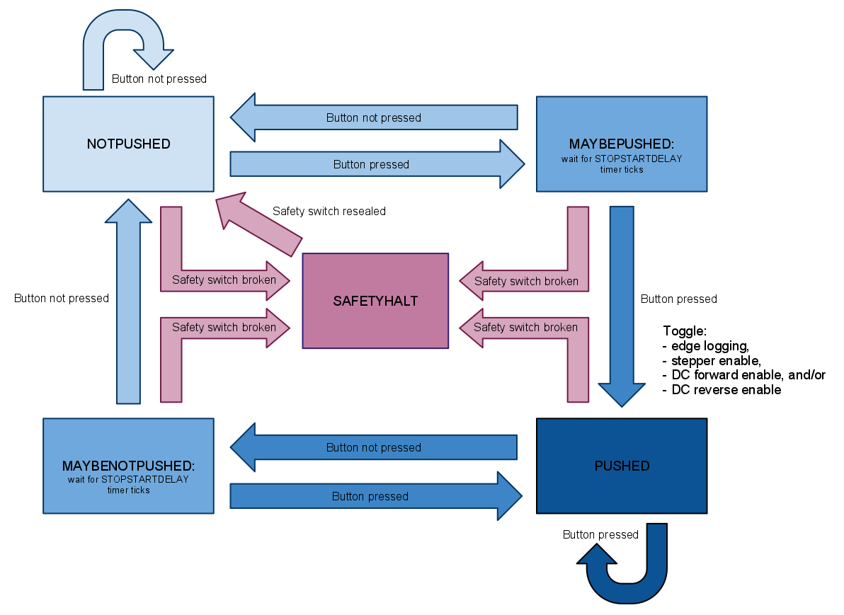
In order to handle the pressing of the “Start/Stop” button, we implemented a function called handleButton that we call continuously while either of the motors is active. This function includes a state machine that toggles the relevant values according to what step in the process the machine is currently executing. The state machine was designed to debounce the button to reduce any error possible from pressing the button at human speeds. The state machine is shown in Fig. 21↓.
There are five states: two for the states of the button, whether or not its pressed or not pressed, two for transitioning between states, and one for handling safety switch toggles. At the transition states, we check to make sure that the transition is valid by having the machine stay in the state for a set delay, STOPSTARTDELAY timer ticks, which makes sure that the user has held the button down for at least that long before anything is done. Since the output of the state machine depends on the transition to the pushed state, the state machine was implemented as a Mealy machine, where the relevant values are toggled at the transition only. This ensures that a single push of the button corresponds to one action. The actual code that checks whether STOPSTARTDELAY has elapsed is included as part of the Timer0 compare match ISR, explained in Sec. 7.2↓ and shown in Alg. 1↑.
The specific effect of pushing the button depends on the current action that the segmenter is performing. In all cases, the button should halt any motors that are active if the machine is running, or resume any motors that are halted if the machine is paused. At any given time, the machine can only be operating one of the two motors, one of which can be running in either its forward or its reverse direction. The machine can also be recording edges if its doing its first pass over the surface of the fruit. Thus, there are four possible sets of values that need to be toggled, consisting of combinations of: the flag for stepping the motor, the flag for running the DC motor in the forward direction, the flag for running the DC motor in the reverse direction, and the flag that indicates whether or not data from the sensor should be logged. These possibilities are passed into the function handleButton to ensure the proper flags are toggled at the right times.
If, at any time during operation, the machine senses the external enclosure has been opened or has come loose, operation will halt and the machine will enter into a paused state until the electrical interconnect connections are resealed, at which point it will wait for the user to press the stop/start button to begin again.
7.2 Stepper Motor Control
Once the system passes all safety checks and is given the Start command, the first thing it must do is spin the fruit exactly one revolution, keeping track of how far along its rotation it is so the sensor and its data filtering routine can estimate where pulp edges occur (Sec. 7.4↓). Since the drive sequence the MCU must output is tightly coupled with an understanding of the hardware, it is defined in Section 6.2↑. All that remains is to achieve continuous rotation by stepping through the drive sequence at a constant rate. To do this, we configure an interrupt on Timer0 that drives the stepper motor circuit (among other things). The timer is configured with a ÷1024 prescalar and a compare-match of 40 ticks. The interrupt triggers and clears on match. With a 16 MHz system clock, this works out to 40⋅(1024 ⁄ 16 × 106) = 2.56 ms per tick, where every 8th tick adds to the total number of steps taken (or 20.48 ms), and the step count modulo four is the time index in the drive pattern, which is output on four port pins. The ISR only changes the state of the stepper motor if a global flag set in the main loop is enabled; during cutting it is false and the step counter doesn’t increase, so the position doesn’t change.
7.3 DC Motor Control
In order to move the CD tray up or down, the three H-bridge input pins EN, IN1, and IN2 discussed in Sec. 6.1↑ must be set appropriately. The software uses the Timer0 compare-match ISR, first introduced in Sec. 7.2↑. When the main function has rotated the fruit to a suspected edge, it sets a global flag indicating the DC-motor-down state. It also zeros a global knife timer. During the next instance of the Timer0 interrupt that updates motor statuses (at most 20.48 ms later), the ISR sets the three H-bridge pins appropriately--with exactly one of IN1, IN2 high and the other low--and increments the knife timer. Each subsequent invocation of the ISR continues this action until the DC-motor-down state is no longer asserted. Defining this knife timer is how we stop the tray from moving at a certain point. There are also mechanical measures that physically prevent the tray from over extending in either the up or down positions.
Once the knife timer expires, the main loop turns off the DC-motor-down flag and asserts DC-motor-up, again zeroing out the knife timer. The ISR behaves exactly as before, this time setting the IN1 and IN2 pins to the opposite of what they were before. When the knife timer hits a (possibly different) preset value, the motor is halted and the main loop disables the motor-up flag. The cutting operation can be extended flexibly, though. That is, we default to using two cutting strokes per edge: after the first down-cut, the knives pull up slightly and then come down again, hopefully driving deeper than with only one slice per edge.
The pseudocode in Alg. 1↑ combines all these elements, along with the other tasks necessary for stepper and button control. Note that it is entirely up to the main software loop to control dcFwdEnable and dcRevEnable. That (slow, interruptible) loop is also what performs overhead functions like setting LED colors and printing debugging info over the UART. Practically speaking the commented source code in Sec. 15↓ is the best reference for more detail on this procedure.
7.4 Sensor Data Parsing/Filtering
7.4.1 ADC Setup
The ADC setup is adapted from Prof. Land’s example code. Since we don’t care too much about quantization noise (as long as large spikes are discernible from small ones), we chose to use 8 bits of output, left adjusted so that only the ADCH register needs to be read.[D]
[D]The left-adjust avoids the potential fatal problem of halting the ADC by reading ADCL without a subsequent ADCH read.
As discussed in Sec. 6.3.2↑, the converter is configured to use the AREF pin as a maximum amplitude reference. Last, the ADC clock--independent from the master pulses that drive the Timer0 ISR--is configured to run at 125 kHz, though this is somewhat of an afterthought since the ADC conversions are triggered from the Timer0 ISR; it is not free-running. Consequently, all ADC interrupts are disabled. Pin A.6, or channel 6 of the MCU’s available single-sided ADC channels, is setup as input.
When initializing these settings, we also begin a conversion before starting any of the actual program logic. This seems to be common practice since the first run of any ADC channel takes twice as long as all subsequent conversions: 25 ADC clock cycles (25/125kHz) as opposed to 13 ADC clock cycles. Doing this here avoids the problem of a single sporadically long conversion breaking timing constraints with the rest of the program. However, it’s worth noting that the 2.56 ms timer match rate that schedules the main ISR is nearly (2.56 × 10 − 3) ⁄ (13 ⁄ 125 × 103 Hz ) ≈ 25 times slower than the time needed to perform one ADC conversion, so it is entirely legal to triggered a conversion in one ISR execution and expect it to be finished by the next time the interrupt runs. This is in fact exactly what we do--except the ADC sampling is 8 times faster than actual stepper motor movement, so we accumulate the 8 values over the interval of each step, dumping the values into the appropriate step-number-indexed bin whenever the stepper advances. Semantically this is the same as non-sliding window averaging; the only difference is that the result is not normalized to save a slow and imprecise division operation.
7.4.2 Finding Edges
The function edgeFind must take in all the ADC values accumulated and dumped into the global array and estimate from there where the grapefruit edges are. The algorithm works by finding the largest peak in the data set, calling it an edge, and flagging data points within a threshold on either side of the newly detected edge as "processed," so that we never consider them again. This threshold is the minimum typical segment width, expressed in steps. We then loop, finding the next highest peak and so on. This way, all data is addressed, and edges are inserted even in noisy data if the spacing of the previously located edges (i.e. the ones we’re more confident about) suggests that there should be one. The flagging operation treats the data as circular, acknowledging the periodic nature of the collection pass.
Empirical results indicate that this is a more robust system than our original comparator/differentiation-based algorithm, detailed below. In order to debug this “ranked confidence with threshold” algorithm, we can easily export the raw ADC data into Matlab and overlay the detected edge locations. For a white grapefruit whose edges generate substantial sensor flicks, the results look like Fig. 22↓. We’ve found that letting the dulled, but firmly inserted sensor tip make one or two passes around the grapefruit works best before actually collecting data to make decisions off of. It turns out that the probe slices through the soft flesh, but not the edges, removing a substantial amount of false positives with this trick.
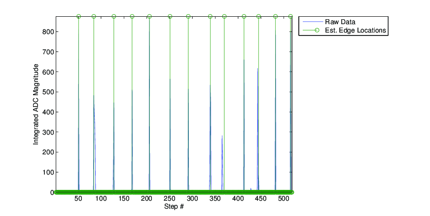
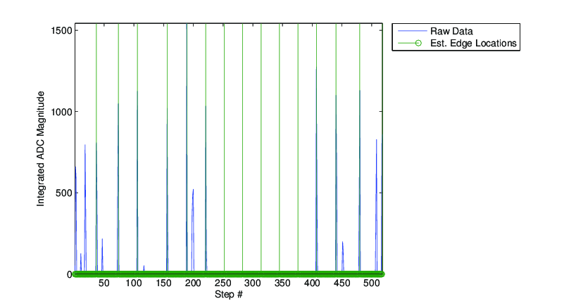
Figure 23↓ on the other hand, shows both the poorer performance of non-white varieties due to textural variations, and the ability of the algorithm to insert edges in the most likely places, even when there is no data there (note especially steps 250-375 of the figure).
The hardware comparator output, which is in the range {0, + VDD} volts, is fed into PORTD.3, corresponding to asynchronous hardware interrupt INT1, which is configured to trigger on a rising edge. Because VDD > 2.5 V (the approximate threshold for the MCU when powered with VDD = 5 V), the comparator’s edges are sufficient to trigger the interrupt. The interrupt service routine (ISR) that is invoked simply saves the current location of the stepper motor, in steps, into a global array of potential edge locations. To avoid overwriting this data, known hereafter as edgeLocs[], a flag indicates whether to log flicks; this is only set high for the initial pass around the fruit, thus disabling flick logging when the stepper engages again when it moves the fruit to cut.
As one might expect, the data in edgeLocs[] is noisy. We have seen empirically that, for a fixed comparator threshold level across several grapefruits, the biggest corruption is in the form of false positives clustering around true edges. That is, just before and just after a true edge is reported, there are multiple spurious detections. However, there remain large gaps between clusters of detections, corresponding to the period during which the knife is cutting through pulp. To exploit this fact, we can better estimate edge locations by filtering the redundancy out of edgeLocs[] via a “thresholded derivative” method. We take the first consecutive difference (discrete analog of a derivative) and look for large values--that is, large jumps in the raw stored locations. In between these large jumps, we average the data over each “plateau” in edgeLocs[], effectively collapsing the multiple triggerings for each true edge into one record. See the pseudocode in Alg. 2↓.
for ii ← 1:length(edgeLocs)
-
edgeDiff  ←  edgeLocs[ii] - edgeLocs[ii-1]
if edgeDiff > THRESH
-
add average of last ii-prevIdx measured edge locations to foundEdges array
increment number of true edges found
prevIdx ← ii
else-
accumulate edgeLocs[ii] onto running sum (to be dumped and averaged eventually)
end -
end
Algorithm 2 Finding true edges from the noisy raw data recordings (omitting housekeeping for clarity). Deprecated method.
This algorithm allows us to go from an initial recording of 100-200 potential edges to a set of only ~15 best estimates. The (hardcoded) THRESH was set based on empirical diff(edgeLocs[]) data plotted in Matlab, allowing us to see the optimal level for differentiating between inter-edge flicks false alarms.
8 Failures
8.1 Initial Design: Image Processing
Our initial design was to have a camera mounted at the surface of the fruit pointing toward the center so that we could find the edges in a grapefruit by processing images as we rotate the fruit. In theory, we would only need to process a few lines from the fruit at the center of the field of view, searching for some derivative change in pixels that would indicate an edge is present. However, there were several problems with this idea. For one, cameras are expensive, which we may not have had the budget for, and interfacing with a camera requires a lot of overhead. Retrieving the signal would be relatively slow as well, since images are large, which means if the accuracy of the machine depends on the quality of the images, accuracy would be inversely proportional to execution time. On top of this, the execution time of our algorithm would have added some time to the process at each frame. Lastly, from experience we found that edges can be extremely difficult to see, even with a human eye, which made us question the upper limit on performance that was possible using this method, even with color filtering techniques. By using a force sensor, we believe we found a cheaper, more robust solution to edge finding.
8.2 Hardware Modifications
Throughout the development process, we made several modifications to the hardware after previous methods didn’t work or required improvement.
- The original idea was to just drag the force sensor across the surface of the fruit at an angle, which turned out to be useless, so a penetrating probe was added to the sensor
- The original idea also involved cutting out single pieces, which would make it very difficult to account for variability in piece width, which was replaced with the idea of cutting around each edge
- The probe tip on the cantilever was too sharp and was cutting through edges, so we had to dull the edges of the blade
- The base holding the grapefruit went through several changes as it was unsteady and did not grip the grapefruit well enough
- The voltage driving the DC motor was upped several times to generate enough force to fully penetrate the fruit, going from 9V to 10.5V and finally to the maximum we could achieve for cheap, 12V
- The piece of fiberboard holding up the CD tray didn’t provide enough support, so we added dowels to support the other side of the tray
- The original axis for the rotating knives was optimized for large fruit, so we had to adjust it to be able to handle smaller cases
- (Deprecated) The input signals were too small for the comparator, so we implemented an amplifier to boost the signal.
Part III. Results
9 Speed of Execution
As detailed by Table 1↓, the device can cut one half of a grapefruit in about a minute and fifteen seconds. The majority of this time is spent after initial scanning and edge location, during the cutting phase. If we speed the cutting step up, we might not allow enough time for the knives to dig sufficiently deep into the fruit. Speeding up the scanning phase by either removing the extra “pre scan” cutting rotations or increasing the stepper speed results in more nosy artifacts in the sensor data. For comparison, we estimate that an able bodied human can do the same amount of work in approximately 40 seconds, working at at comfortable but not lazy pace. Clearly our device is outclassed in terms of speed with the default settings. However, if we double the motor speed and eliminate the extra initial fruit revolutions, we could perform a much poorer quality cut in about 11 ⁄ 2 sensing + 2 process + 11 ⁄ 2 cutting rotation + 31 cutting knife motion ≈ 44 seconds.
10 Accuracy
Thanks to the grapefruit donation from Wegmans, we were able to test on nearly twenty different samples, spread across the white, ruby red, and dark red varieties. Due to the physical nature of the project, and the variance of the organic grapefruit, it’s not immediately obvious how to gather quantitative accuracy data. Ideally we would like to measure the percentage of edges correctly located and percentage of pulp extracted. We can estimate the former, but there have been cases where we think that we hit or miss edges due to chance. That is, if the sensor data isn’t good and we can’t find the edges well, the results could look artificially good due to the algorithm’s inferred edges lining up with an oddly regular grapefruit. Also, the machine currently cuts out edges and, optionally, a smaller portion from the rind. It doesn’t free the segments as we initially hoped, so we cannot have a measure of true “extraction efficiency.”
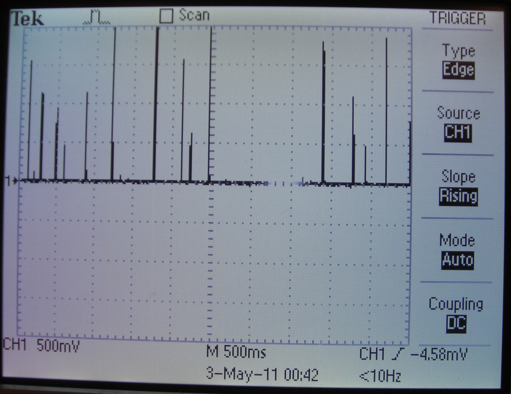
Our foremost comment on accuracy is that it depends heavily on grapefruit species. White grapefruits, with their large average size, soft flesh, and pronounced edge separators, work best with our system. Of the ten white halves we’ve tested, the raw piezoelectric flex sensor voltage looks the best on the scope (Fig. 24↓). During the cutting phase, the first few edges are often located very well while the later edges aren’t found as accurately. There seems to be almost a linear drift affecting the accuracy of location there. That said, we estimate an edge cutting error rate of approximately 15%, corresponding to 2 imperfect cuts on a grapefruit with 13 edges.
The dark red grapefruit, as explained in the images at the top of this site, are much much smaller than the other varieties, so we the fixed-width knives have a hard time cutting them accurately, and we can’t at all use the radial rind-knives. There are no reliable, repeatable data for this set since mechanical size limits preclude cutting.
Ruby reds behave better than dark reds, thanks to their size, but worse than whites, due to their texture. The biggest problem with accuracy is correctly finding edges, as explained further in Sec. 12↓. Furthermore, the 12V available from the computer PSU powering the DC motor with isn’t quite enough. We only rarely penetrate the fruit to the depth we desire, and adding the rind knives makes the overall depth of the cuts shallower.
11 Safety
Because our design involves automated moving knives, we tried to address any safety concerns which a user could have. We did this by including an external enclosure for the device and an emergency halt button. Complementing these measures, a simple user interface guarantees a much lower probability of misguided user operation. We firmly believe that the operation of this device is absolutely safe for any adult to operate.
11.1 Enclosure & Electrical Interconnect Structure
The safety enclosure was designed specifically to protect the user from potentially hurting themselves during operation. Two exposed pieces of wire on opposite sides of the base platform lid have to be shorted together to allow operation; because this fail-safe is more than just a button or switch, the average user would have a hard time beating this safety measure without a long piece of conductive material. See Sec. 6.4↑ for a full description of the setup.
When the cover is on, the two interconnects are shorted, which the MCU detects as an input pin shorting to ground. Likewise, if the cover is not on, the MCU will not allow the stepper or knife motors to start moving, and if the cover is removed during operation, the MCU immediately halts all motion. Thus, the enclosure makes sure that no knives or sharp pieces are exposed whenever the machine is moving them, which we believe drastically reduces the chance of injury.
11.2 Emergency Halt
We implemented a button which pauses and resumes operation of the machine; for more details see Sec. 6.5↑ and Sec. 7.1↑ for descriptions of the user interface and how we handled button presses, respectively. We imagine this button will further reduce any risks associated with our machine, acting as a second line of defense. If, by some chance or tampering, the machine operates without the enclosure present, any alarmed user may hit the halt button to pause the machine.
Furthermore, if perhaps the software fails and bypasses the enclosure check while ignoring user inputs from the halt button, the power button is directly hardwired to the power of the MCU, and is conveniently located next to the pause button. In fact, because the user interface is so simple, hitting either button in the event of an emergency will immediately stop the machine.
11.3 Interference with Others’ Designs
We don’t anticipate any interference with anyone else’s design, except perhaps for a negligible amount of RF noise that is inevitable with the operation of a small motor. For better or worse, the audible noise created by the metal-on-metal clacking and clanging of the knives, along with the loud rotations of the stepper motor, are much more annoying to the human designers of other teams than any radiated electrical signals are to their designs.
11.4 Usability
Though the fruit is initially difficult to insert, the machine does do the tedious work for you, which normally requires some dexterity. As long as the user can cut the fruit in half initially, the device could perhaps be beneficial towards the disabled that lack the suitable fine motor skills to extract pulp themselves. However, the quality of the sensor measurements depend largely on the initial cut being level and the fruit being placed on the platform exactly centered.
With this in mind, the usability of the project is appropriate for a “proof of concept” phase, where human factors have been superseded by technical performance.
Part IV. Conclusions
12 Results vs. Expectations
Our overall assessment of the results, expressed in a manner to which engineers are accustomed, is that
EffortResults≫1
Concerning usability, we had hoped that the final product would be as user friendly as a kitchen appliance. In the final product, however, design limitations necessitate a specific sequence of actions for successful operation. One aspect is the insertion of the grapefruit: positioning the grapefruit accurately on the four center nails on the platform, which is extremely important for smooth operation, is more difficult than we pictured because there are many elements in the way. One component that is in the way, and which is not adjustable, is the pivot point on which the rotating knives are mounted. In design, we needed the rotating knife axis to be mounted be as low and as close to the surface of the grapefruit as possible, in order to carve out an arc that is a close approximation to the inner rind of the fruit. We bent the nails in a uniform direction to ease the insertion of the grapefruit, but this means that the fruit must be positioned at an offset from the center and slid onto the center of the platform as the fruit is pierced by the nails. Furthermore, the torsion spring also obstructs the placement of the grapefruit, so the user must first bend the spring back and lock it there by inserting it into a loop of wire attached to the CD support. Finally, the edge sensor is also in the way, since it must be resting near the surface of the fruit during operation, so the sensor must be rotated away before a grapefruit is placed on the platform.
Another thing to consider when using the machine is that the rind cutting knives are positioned to cut at a fixed radius, which means that an attempt to cut a grapefruit that has a smaller radius will be guaranteed to fail as the DC motor does not have enough power--nor are the knives sharp enough or shaped well enough--to cut through the outer rind. The user has the option of detaching the rind knives if this is the case, so that at least they may cut the radial edges are automatically cut. In that case, the user must cut their own circumference around the fruit either before or after mounting it on the platform.
Aside from these physical annoyances, the performance varies widely with grapefruit variety. Of the three varieties tested--white, ruby red, and dark red--white grapefruits are the easiest to cut. The flex sensor deflects in sharp, large motions off of true edges, and cuts easily through pulp and pulp alone. Thus the results match our initial (high) expectations. However, the relatively stiffer ruby and dark red varieties result in more large, false positives in the raw ADC data. Despite motor noise dampening and sensor probe adjustment, the texture of these varieties often times introduces a large flick in the sensor knife mid-segment. If the noise had more regularity we could perhaps design a software algorithm around it; from our moderate number of tests this doesn’t appear to be the case. Again, this is an example case where we expected better performance across fruit varieties.
There are a few apparent solutions to these problems, even within the $75 budget. First, the entire CD tray apparatus could be mounted on a swinging hinge such that it can be rotated out of the way when the user has to insert or remove the fruit. Second, if we could combine the flex sensor with a color camera and optical filter system, as we had originally planned, we may very well be able to generate better estimates of edge location by combining the two sensor measurements to make up for weaknesses each presents alone. More reliable edge detection could not only reduce the error rates reported in the Accuracy section 10↑, but could even speed up operation overall if we don’t need to make multiple passes around the fruit.
13 Conforming to Standards
There are no standards relevant to our project.
14 Intellectual Property
14.1 Reuse code or design
We reused both knives from the Chef’n Grapefruiter(TM). In the original design of that product, however, the knives form a fixed wedge shape, which goes against the primary goals of our project, so we cut the stationary knives down the middle and cut the rotating knife in half as well. We fully acknowledge the origin of these knives, and, as mentioned in Sec. 14.5↓, would not reuse them if we were pursuing a patent or any form of commercialization.
14.2 Public domain code
We did not use any public domain code, in whole or in part.
14.3 Reverse-engineering
We did not reverse engineer any software or hardware.
14.4 Non Disclosure Agreements
We did not sample any parts and thus did not have to sign any NDAs.
14.5 Patent Opportunities
This project does show the capacity for a patent. If we can improve the performance and speed of the unit, it could conceivably be redesigned for commercial sale, at which point the protection of a patent would be helpful. The exact solution to the “problem” is novel as far as we have seen online, and even though the Grapefruiter(TM) device doesn’t seem to be patented, it would be in our best interest, personally and ethically, to fabricate our own knives instead of cannibalizing them as we did in this project.
14.6 Publishing Opportunities
In the world of academia there is almost definitely no interest in what we have developed. Perhaps if we discovered some novel way of using piezoelectric flex sensors for feature detection it could make an estimation and detection, signal processing, or more specific “special topic” conference or journal. Realistically, the prime outlet for this project is in the hacker and maker community literature. We will openly entertain submission to Circuit Cellar, hackaday, avrfreaks, hackedgadgets, etc.
14.7 Ethical Considerations
We sought to adhere to the IEEE Code of Ethics in our design, particularly considering our device could potentially cause harm the user if created carelessly. The first standard states that we “accept responsibility in making decisions consistent with the safety, health, and welfare of the public, and to disclose promptly factors that might endanger the public or the environment.” We tried our best to make our device safe for adult use, and put safety first during any design process. There are three levels of safety: a simple user interface to minimize unintentional misuse, an electrical safety interlock to immediately halt all knives and motors if the clear plastic enclosure is removed, and power and halt buttons to give users immediate, physical control over the operation of the machine. These work in concert to ensure that those that use our machine will not be harmed. Furthermore, we have documented all potentially harmful aspects of our design and how we handled them in this document, and have made this document available to anyone that should use it. The source code is completely open, and hardware designs are well documented with pictures and schematics, so anybody who attempts to copy our design will be similarly aware of such safety measures.
Regarding IEEE point number 3, we have above shown complete honesty in stated results. The unit clearly works best on white grapefruit only, and faces severe shortcomings on other varieties. Finally, ample acknowledgment can be found in Sec. 19.1↓, in line with principle number 7, that members of the IEEE should seek criticism of technical work and credit others when due.
14.8 Legal Considerations
There are no obvious legal considerations pertinent to our grapefruit segmenter. We do imagine, though, that if this product were to be made commercially available, it wouldn’t be without a “for use under adult supervision only” or some similar safety warning regarding the small parts and sharp moving pieces crucial to the design.
Part V. Appendices
15 Appendix A: Source Code
There is only one main C source file and one header H file, included below with syntax highlighting performed by Notepad++. UART code can be found here and here :
Exported from Notepad++ /** * stepper.c * ECE 4760 Final Project: Grapefruit Segmenter * * Authors: Kevin Martin <ksm76@cornell.edu> * Hyundo Reiner <hpr6@cornell.edu> * * Last Modified: 5/2/11 * * This version of the code uses ADC and a more sophisticated, robust * signal processing solution to better estimate true edge locations. * * The signal winds up binned into 518 categories, one for each step; * we perform 8 A to D conversions per step */ // Op amp non-inverting amplifier settings // R1 = 9.91 kOhms // R2 = 991 kOhms // G = (1+R2/R1) approx 100 // orange sensor lead is ground // LED standard: // PORTB.0 = green, 1 = red, 2 = violet, 3 = orange /** * INCLUDES */ #include <inttypes.h> #include <avr/io.h> #include <avr/pgmspace.h> #include <avr/interrupt.h> #include <stdio.h> #include <util/delay.h> #include <string.h> #include "uart.h" #include "kyundoExtras.h" // UART file descriptor // putchar and getchar are in uart.c FILE uart_str = FDEV_SETUP_STREAM(uart_putchar, uart_getchar, _FDEV_SETUP_RW); // Bootup string. It's long, so save in FLASH /** * DEFINES */ //timeout values for each task #define SAFETYON 1 #define DEBUG 1 #define NUMSLICES 2 #define ROTATIONS 1 #define STEPSPERROT 518 #define OFFSET 129 // Number of STEPS between sensor and cutting head. (~4.8 * teeth) #define FLICKDELAY 3 #define MINSEGMENT 30 #define MAXEDGES 17 // extra cutting rotations and corresponding steps: 1 - 518, 2 - 1037 , 3 - 1555 #define PRESCANSTEPS 1037 // NOTE: With the /1024 clk prescalar and mod arithmetic in the ISR, each tick // below corresponds to 8*2.56=20.48ms, so scale these constants accordingly #define DCTIMEDOWN 35 #define DCTIMEUP 20 // Subsequent cut timing #define DCTIMEDOWN2 20 #define DCTIMEUP2 12 #define STOPSTARTDELAY 2 #define NOTPUSHED 1 #define MAYBEPUSHED 2 #define PUSHED 3 #define MAYBENOTPUSHED 4 #define SAFETYHALT 5 #define SCANNING 1 #define CUT_STEPPER 2 #define CUT_DCDOWN 3 #define CUT_DCUP 4 /** * DECLARATIONS */ // task subroutines void initialize(void); //all the usual mcu stuff void edgeFind(void); void handleButton(uint8_t); /** * GLOBALS */ /* Define the step table - Full Mode Sequence Step A B A\ B\ 0 1 1 0 0 1 0 1 1 0 2 0 0 1 1 3 1 0 0 1 where pins C.0,1,2,3 are A, A\, B, B\ respectively */ uint8_t drivePattern[4][4] = {{1, 1, 0, 0}, {0, 1, 1, 0}, {0, 0, 1, 1}, {1, 0, 0, 1}}; uint16_t edgesFound[STEPSPERROT]; uint8_t dcFwdEnable; // Knife-dropping motor settings uint8_t dcRevEnable; uint8_t stEnable; // Stepper motor settings uint16_t stepsTilHalt; uint8_t foundIdx; // How far into the foundEdges array we are uint8_t edgeLogging; uint8_t numEdges; uint8_t stopStartState; uint8_t ticks; volatile uint16_t adcStepAccum; // Summation of 8 ADC values volatile int16_t rawData[STEPSPERROT]; // Buffer into which adcStepAccum is dumped volatile uint8_t safetyFlag; // Main safety flag volatile uint8_t a, ap, b, bp, curStep; // A, Aprime, B, Bprime - for stepper volatile uint16_t steps; // Number of steps the motor turned volatile uint16_t logIdx; // Index into edge logging array volatile uint16_t dcTime; // Time for DC motor to be active volatile uint8_t stopStart; // Flag from the stop/start button volatile uint16_t stopStartDelay; // Debounce timer /** * INTERRUPT SERVICE ROUTINES */ /** * Timer0 compare ISR * * Drives the stepper motor when the state calls for it, keeping track of * how many steps the motor has moved. Note pattern moves backwards to obtain * a certain direction of rotation relative to the "flick" sensor. * * It also acts as a master timer for commanding the DC motor and overseeing * the debouncing in the handleButton routine. * * Also initializes, sums, and stores ADC conversions */ ISR (TIMER0_COMPA_vect) { // Save last ADC result and init new ADC capture if (edgeLogging && steps >= PRESCANSTEPS) { adcStepAccum += ADCH; SET(ADCSRA, 6); } // So that the stepper runs five times slower than ADC if((++ticks % 8) == 0) { // Check if stepping the motor if (stEnable) { curStep = 3 - ++steps % 4; a = drivePattern[curStep][0]; ap = drivePattern[curStep][2]; b = drivePattern[curStep][1]; bp = drivePattern[curStep][3]; PORTC = a | (ap << 1) | (b << 2) | (bp << 3); } // Watch for overflow if (edgeLogging && steps > PRESCANSTEPS && logIdx < STEPSPERROT) { // Write accumulated ADC value to the appropriate step rawData[logIdx++] = adcStepAccum; // Start new conversion - this takes 13 ADC clock cycles, or ~0.1ms adcStepAccum = 0; } // Check if dropping knives if (dcFwdEnable) { SET(PORTA, 0); SET(PORTA, 1); CLR(PORTA, 2); dcTime++; } // Check if raising knives if (dcRevEnable) { SET(PORTA, 0); SET(PORTA, 2); CLR(PORTA, 1); dcTime++; } if (stopStartDelay < STOPSTARTDELAY) { stopStartDelay++; } } } /** * FUNCTIONS */ /** * Entry point and state machine * * Note: initialize() call must come first. Remove ISP programming header to * avoid extra reset after bootup. * * Note: There is no explicit safety code in this function. handleButton() * handles that logic as well, and it is called within the while() loops that * run during safety-conscious operation (i.e. when any motors are moving). */ int main(void) { uint16_t ii, jj, cutTimeDown, cutTimeUp; initialize(); steps = 0; stepsTilHalt = PRESCANSTEPS + ROTATIONS*STEPSPERROT; // Wait for Start button, and turn on green LED SET(PORTB, 0); fprintf(stdout, "Waiting for start...\r\n"); while (READ(PINB,5)) { } fprintf(stdout, "Starting scan\r\n"); // Start seeking edges, and turn on violet LED SET(PORTB, 2); CLR(PORTB, 0); while (steps < stepsTilHalt) { handleButton(SCANNING); } // Stepper motor has made the predetermined number of revs, so disable it stEnable = FALSE; edgeLogging = FALSE; // Print list of edge locations #if DEBUG fprintf(stdout, "rawData:\r\n[%d", rawData[0]); for(ii = 1; ii < STEPSPERROT; ii++) { fprintf(stdout, ",%d", rawData[ii]); } fprintf(stdout, "]\r\n\r\n"); #endif // Call edge finding function edgeFind(); // Print filtered list #if DEBUG fprintf(stdout, "edgesFound:\r\n[%d", edgesFound[0]); for(ii = 1; ii < STEPSPERROT; ii++) { fprintf(stdout, ",%d", edgesFound[ii]); } fprintf(stdout, "]\r\n\r\n"); #endif ///////////// Start cutting // Change LEDs - orange for caution CLR(PORTB, 2); SET(PORTB, 3); fprintf(stdout, "\tSTARTING TO CUT\r\n"); CLR(PORTA, 0); // Rotate by offset first stepsTilHalt = OFFSET - FLICKDELAY; steps = 0; stEnable = TRUE; while (steps < stepsTilHalt) { handleButton(CUT_STEPPER); } // Halt stepper stEnable = FALSE; stepsTilHalt = 0; // Go to each edge and cut, possibly multiple times for (ii = 0; ii < STEPSPERROT; ii++) { stepsTilHalt++; // Consider next step if (edgesFound[ii] == 0) { continue; } // If we're here, then edgesFound[ii] == 1 steps = 0; // Rotate fruit to this step offset location stEnable = TRUE; while (steps < stepsTilHalt) { handleButton(CUT_STEPPER); } stEnable = FALSE; stepsTilHalt = 0; // Move knives up completely SET(PORTA, 0); CLR(PORTA, 1); SET(PORTA, 2); _delay_ms(80); CLR(PORTA, 0); // Cut, possibly in multiple strikes for(jj = 0; jj < NUMSLICES; jj++) { // Default to short strokes cutTimeDown = DCTIMEDOWN2; cutTimeUp = DCTIMEUP2; // Make first strike have the long downstroke if (jj == 0) { cutTimeDown = DCTIMEDOWN; } // Make last strike have the long upstroke if (jj == NUMSLICES - 1) { cutTimeUp = DCTIMEUP; } dcTime = 0; dcFwdEnable = TRUE; // Cut down while (dcTime < cutTimeDown) { handleButton(CUT_DCDOWN); } // Halt DC motor CLR(PORTA, 0); dcFwdEnable = FALSE; // Cut up dcTime = 0; dcRevEnable = TRUE; while (dcTime < cutTimeUp) { handleButton(CUT_DCUP); } // Halt DC motor CLR(PORTA, 0); dcRevEnable = FALSE; } } // for each edge // FINISHED! Raise knives, and ENTER IDLE MODE, and dance the LEDs :D fprintf(stdout, "\r\n-- FINISHED! --\r\n"); SET(PORTA, 0); CLR(PORTA, 1); SET(PORTA, 2); _delay_ms(40); CLR(PORTA, 0); while (TRUE) { // Dance the LEDs!! PORTB &= 0xF0; SET(PORTB, 0); _delay_ms(125); CLR(PORTB, 0); SET(PORTB, 1); _delay_ms(125); CLR(PORTB, 1); SET(PORTB, 2); _delay_ms(125); CLR(PORTB, 2); SET(PORTB, 3); _delay_ms(125); } } /** * For one logged set of raw logged ADC data, find the edge location. * This is how we filter out false positives. * * The algorithm works by finding the largest peak in the data set, calling * it an edge, and flagging data points within a threshold on either side * of the newly detected edge as "processed," so that we never consider * them again. This threshold is the minimum typical segment width, * expressed in steps. We then loop, finding the next highest peak and so * on. This way, all data is addressed, and edges are inserted even in * noisy data if the spacing of the edges we're more confident about * suggests that there should be one. The flagging operation treats the * data as circular, aknowledging the periodicity of the sensing operation. * * The loop ends when all edges have been processed. */ void edgeFind() { int32_t sum = 0; int16_t ii, jj; int16_t nextEdgeIdx = 0, curMax; while(sum != -518) { // Find and record location of max value of myRawData // Matlab: find(raw_data == max(raw_data),1) curMax = -1; for(ii = 0; ii < STEPSPERROT; ii++) { if(rawData[ii] > curMax) { curMax = rawData[ii]; nextEdgeIdx = ii; } } // Mark steps as processed by setting to -1 (careful to use mod to wrap around) for(ii = -MINSEGMENT; ii < MINSEGMENT+1; ii++) { // How C defines mod is DIFFERENT from how Matlab does. // e.g. neg % pos = neg always. It's mathematically valid, but just an // alternate definition. Thus we add STEPSPERROT to ensure that // nextEdgeIdx + ii > 0 for all ii. jj = (nextEdgeIdx + ii + STEPSPERROT) % STEPSPERROT; if(jj < 0) { fprintf(stdout, "jj = %d\r\n", jj); } rawData[jj] = -1; } // Find sum sum = 0; for(ii = 0; ii < STEPSPERROT; ii++) { sum += rawData[ii]; } fprintf(stdout, "nextEdgeIdx = %d, sum = %d\r\n", nextEdgeIdx, sum); edgesFound[nextEdgeIdx] = 1; } } /** * Debounces and handles the "Stop/Start" button appropriately based on * the state the machine is in when the routine is called (specified via * input argument "scenario" */ void handleButton(uint8_t scenario) { // Check for safety #if SAFETYON if (READ(PINB,4)) { if(stopStartState != SAFETYHALT) { // Only output warning on transition into this state. Light RED LED fprintf(stdout, "!!! UNIT UNSAFE!!!\r\n"); SET(PORTB, 1); } stopStartState = SAFETYHALT; stEnable = FALSE; edgeLogging = FALSE; dcFwdEnable = FALSE; dcRevEnable = FALSE; } else { #endif switch (stopStartState) { case NOTPUSHED: if(!READ(PINB,5)) { stopStartState = MAYBEPUSHED; stopStartDelay = 0; } break; case MAYBEPUSHED: if (stopStartDelay == STOPSTARTDELAY) { if (!READ(PINB,5)) { // Transitioning to PUSHED state, so toggle motor values stopStartState = PUSHED; switch (scenario) { case SCANNING: stEnable = !stEnable; edgeLogging = !edgeLogging; break; case CUT_STEPPER: stEnable = !stEnable; break; case CUT_DCDOWN: dcFwdEnable = !dcFwdEnable; break; case CUT_DCUP: dcRevEnable = !dcRevEnable; break; } } else { stopStartState = NOTPUSHED; } } break; case PUSHED: if(READ(PINB,5)) { stopStartState = MAYBENOTPUSHED; stopStartDelay = 0; } break; case MAYBENOTPUSHED: if (stopStartDelay == STOPSTARTDELAY) { if (READ(PINB,5)) { stopStartState = NOTPUSHED; } else { stopStartState = PUSHED; } } break; #if SAFETYON case SAFETYHALT: if (!READ(PINB,4)) { stopStartState = NOTPUSHED; // Transitioning OUT of safety halt, so print another message fprintf(stdout, "Phew! Another lawsuit avoided. UNIT SAFE!!! [Press Start/Stop to Resume]\r\n"); CLR(PORTB, 1); } break; } #endif } } /** * Set up timer for master ISR, I/O pins for user interaction, * ADC for input capture, states for button handling, etc. */ void initialize(void) { uint16_t ii; SET(DDRD, 2); // PORT D.2 is an output for LED DDRC = 0x0F; // outputs to ULN2003AN CLR(DDRD, 3); // Input from sensor ck t DDRA = 0x07; // Outputs to H-bridge - EN, IN1, IN2 DDRB = 0x0F; // Outputs to LEDs, inputs from safety and stop/start switches // Use input pull-up resistors for the start/stop button and safety latch. Active low logic. SET(PORTB, 5); SET(PORTB, 4); // Init the UART -- uart_init() is in uart.c uart_init(); stdout = &uart_str; stdin = &uart_str; stderr = &uart_str; fprintf(stdout, BOOTUPSTRING); // Init the A to D converter using channel 6, left adj, ext. Aref ADMUX = 0b00100110; // Enable ADC and set prescaler to 1/128*16MHz=125,000 and clear interupt enable // Start a conversion; this one takes almost twice as long as all following ADCSRA = 0b11000111; // Set up Timer0 to use interrupt on compare match (and clear) TIMSK0= (1<<OCIE0A); // The combination of prescalar of 1024 and a match figure of 40 give 2.56ms pulses. // We'll do an ADC conversion on each of these, and a motor command every 8 of these OCR0A = 40; TCCR0B= 5; TCCR0A= (1<<WGM01) ; // Twitch the DC knife-drop motor up a little to check the wiring polarity, then halt SET(PORTA, 0); CLR(PORTA, 1); SET(PORTA, 2); _delay_ms(30); CLR(PORTA, 0); // On-board LED for reset monitoring and overall power state CLR(PORTD, 2); // Initialize log params logIdx = 0; foundIdx = 0; memset((void *)rawData, 0, sizeof rawData); memset((void *)edgesFound, 0, sizeof edgesFound); // Be thourough: initialize all other state variables edgeLogging = FALSE; safetyFlag = FALSE; stopStart = FALSE; dcFwdEnable = FALSE; dcRevEnable = FALSE; stEnable = FALSE; steps = 0; ticks = 0; adcStepAccum = 0; dcTime = 0; stopStartDelay = STOPSTARTDELAY; stopStartState = NOTPUSHED; // Enable ISRs sei(); }
Exported from Notepad++ /** * kyundoExtras.h * * Stores the convenient defines and long, annoying strings away from the * logic of the program. */ #ifndef _KYUNDO_EXTRAS #define _KYUNDO_EXTRAS // For easy, less error-prone bit manipulation #define READ(U, N) ((U) >> (N) & 1u) #define SET(U, N) ((void)((U) |= 1u << (N))) #define CLR(U, N) ((void)((U) &= ~(1u << (N)))) #define FLIP(U, N) ((void)((U) ^= 1u << (N))) #define TRUE 1 #define FALSE 0 #define max( a, b ) ( ((a) > (b)) ? (a) : (b) ) #define min( a, b ) ( ((a) < (b)) ? (a) : (b) ) #define BOOTUPSTRING \ "The Kyundo Meiner Inc. 'Gr8fr00t (tm)' Initialized.\r\n\ -----------------------------------------------------------------------------------------------------------------\r\n\ Instructions\r\n\ 1) Carefully place the grapefruit so that the edges line up directly under the knives--\r\n\ such that the fruit is centered properly.\r\n\ 2) Firmly push the fruit onto the support nails.\r\n\ 3) Swing the sensor into position so that the tip drags as close as possible to perpendicular\r\n\ to the edges.\r\n\ 4) Embed the sensor tip into the pulp so that it's almost all the way in up to the white stopper brick.\r\n\ 5) Snap the safety cover onto the unit. Push down hard until all four tabs click in.\r\n\ 6) When the READY indicator is set (Green LED), the unit is safe and you are free to press the START/STOP button.\r\n\ \t6a) If the cover is not on securely, the system will indicate error (Red LED) until the \r\n\ \t safety connection is fixed.\r\n\ 7) -- Watch the machine work! --\r\n\ \t7a) If at any time the machine halts due a safety failure, the Red LED will light and you must replace\r\n\ \t the cover and hit the START/STOP button to resume operation.\r\n\ 8) The system indicates it is done by dancing all four LEDs.\r\n\ ONLY THEN is it safe to remove the cover and take out your delicious, mediocrely segmented grapefruit.\r\n\r\n" #endif
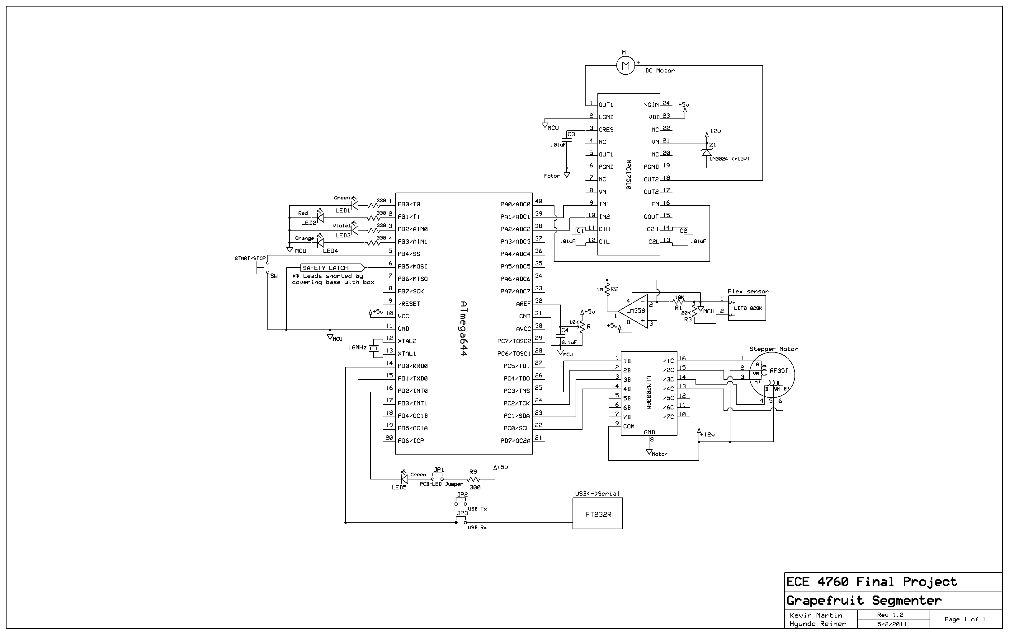
16 Appendix B: Schematics
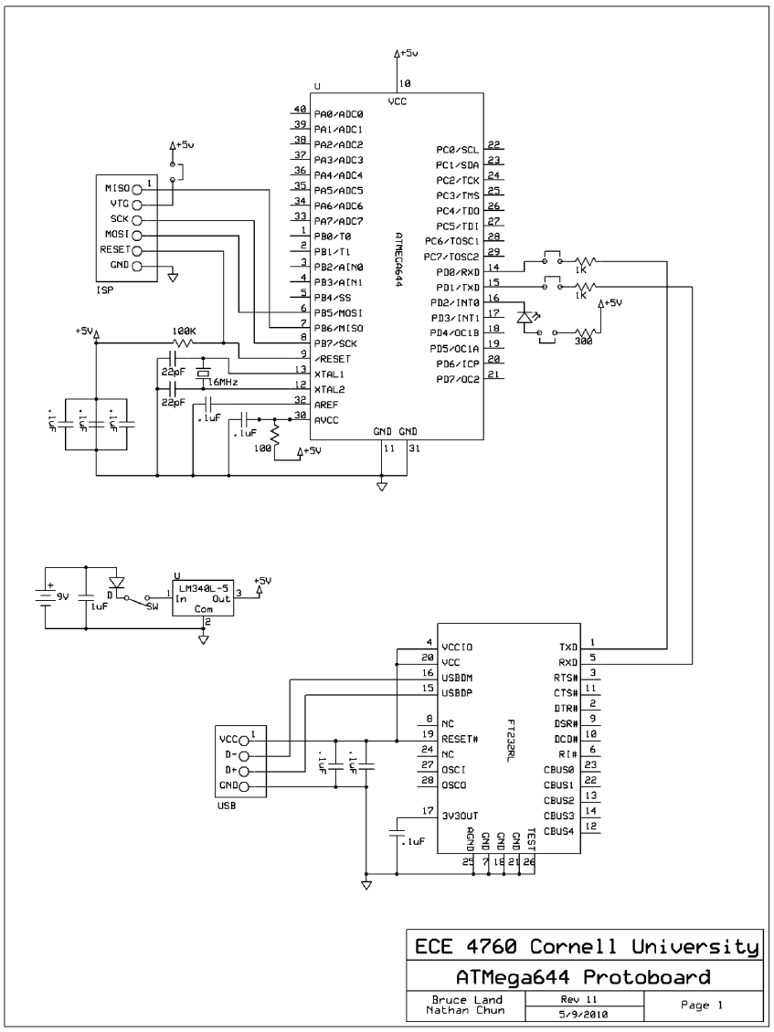
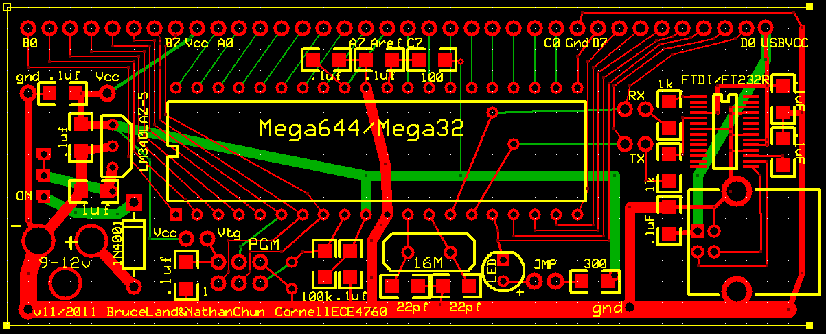
You can download the original ExpressSCH schematic file here. Note that this does not include hardware necessary for the custom protoboard to function. See the appropriate figure for those additional components. The entire circuit is the union of these two diagrams, but separating them as such should make it easier for the reader to separate essential system logic from “overhead”.
17 Appendix C: Parts List
| Item | Description | Source | Cost |
| Custom PCB Breakout Board | Hosts MCU, power, and connections to rest of project | Course | $4.00 |
| Atmel ATmega644 | MCU | Course | $8.00 |
| Wires, resistors, and capacitors | Connectivity, motor control circuitry, filtering, detection, etc. | Free in lab | $0.00 |
| 1N3024 15V Zener diode | Back-EMF Snubbing for DC motor circuit | Free in lab | $0.00 |
| ULN2003AN Darlington Array | Stepper motor control | Free in lab | $0.00 |
| Whiteboard | Analog motor control hardware | Course | $6.00 |
| DC motor | For knife arm | Free in lab | $0.00 |
| PF35T-48 Stepper motor | Fruit rotation | Free in lab | $0.00 |
| LEGO® bricks | Knife mounting and rotation | Preowned (Hyundo) | $0.00 |
| Masonite Pegboard | Structural platform | Lowe’s | $5.00 |
| Plastic enclosure box | Safety | Lowe’s | $5.00 |
| Hardware - 1/4”-20 nuts, bolts, screws | Connections through the fiberboard | Lowe’s & Free in lab | $8.00 |
| Header pins | Custom board connections | Course | $3.60 |
| Freescale MPC17510 H-bridge | DC motor control | Course | $3.60 |
| Generic TSSOP Breakout Board | To host H bridge | Free in lab | $0.00 |
| Measurement Specialties LDT0-028K | Piezo flex sensor for flick detection | Course | $2.80 |
| Chef’n Grapefruiter | Cannibalized for knives | Amazon.com | $14.20 |
| Grapefruit | 18 total , 6 each of 3 varieties | Wegmans Donation | $0.00 |
| Buttons | Power and reset | Free in lab | $0.00 |
| Dowels | Structural support | Wal-Mart | $1.50 |
| 100W Power Supply | Mains to +12V, 2A regulated DC for MCU and motors | Preowned (Kevin) | $0.00 |
| Elastic Bands | For holding sensor onto mount | Wal-Mart | $0.54 |
| Commodity LEDs | Status indication | Free in lab | $0.00 |
| LM358 Dual Op Amp | Piezo Sensor output amplification | Free in lab | $0.00 |
| Alligator clips (x2) | Connecting the DC motor | Course | $2.00 |
| TOTAL | $64.24 | ||
Table 2 Inventory
18 Appendix D: Delegation of Responsibilities
| Kevin | Both | Hyundo |
| Initial motor code | Stepper motor gear and plate assembly | Design and construction of sensor platform |
| Initial edge finding algorithm | Debugging H bridge and stepper code | Design and construction of knife mounts |
| ADC setup | Sensor circuitry | New edge finding algorithm |
| Initial physical construction | Edge finding - implementation | Plate construction |
| Button and LED buildup & circuitry | Debugging overall code | Extensive CD tray modifications |
| Custom 4760 Protoboard construction | Button handling code | Grapefruiter disassembly |
| PC Power Supply Integration | Safety latch system | Mechanically harden all physical components |
| Website formatting | Website content | |
| Gross Simplification | ||
| Soldering and most electrical | Software and testing | Dremelling and most mechanical |
Table 3 Task List
19 Appendix E: References
data sheets, company websites, useful tutorials
- Datasheets
- Vendors
-
References
- Timers on the Mega644
- Stepper Motor Control using a ULN2003 and a microcontroller
- Op amp applications
- Linear Actuator from a CD tray motor - inspiration for entire CD tray apparatus
- A/D and D/A on the Mega32
19.1 Acknowledgments
We would like to thank the Ithaca Wegmans supermarket for graciously donating all the grapefruits we used to to test and demonstrate the project. Though this expense would likely have not counted towards our $75 budget, it saved us a considerable amount of money out of pocket. Thank you again to both Corporate and Mike and Joe from the Produce Department.
We would also like to thank Brian Dyson, the landlord/roommate/close friend of Kevin Martin, without whom the we would not have been able to do much of the structural work at home so easily and comfortably. Brian’s basement workshop complete with soldering irons, a Dremel with a large tip set, styrofoam shaping tool, modeling epoxy, superglue, helping hands, drills and drill bits, screwdrivers and screws, nuts, bolts, and other assorted fasteners were a tremendous help in completing the project. Another roommate of Kevin’s, Russell Wolf, also let us use his oscilloscope so we could effectively work from home.
Cornell Veterinary School Professor of Physiology Dr. Ellis Loew kindly donated both his time and materials to us during the very beginning stages of our project when we were pursuing a camera-based segment-edge detector. His background in vision systems and access to colorimetry lab equipment was useful in characterizing how to best optically filter out rind from pulp.
Last, we would be foolish to omit Bruce Land. He, and ECE 4760, are Cornell treasures. Bruce possesses a seemingly infinite mass of knowledge, and he offers it up in large doses with an almost absurd set of open lab hours. Without his constant, welcome oversight and tutelage in all things mechanical, electrical, and mathematical, we would get so much less out of the class and so much less out of Cornell ECE.