ECE 4760 Final Project
Digital Saxophone
04/24/2012
By Brian Wang
Abstract
My final project was the design of a digital saxophone which can reproduce the sound of an actual saxophone through digitally synthesized electrical waveforms. The digital saxophone consists of a microphone to sense the user blowing into a mouthpiece, push-buttons to control the note to be played, and the Atmel644 Micro-Controller which processes the inputs and produces the digital output that sounds like a saxophone.
High Level Design
Overview:
There are several ways to digitally produce sounds, for example Karplus Strong, FM synthesis, and additive synthesis. The selection of methodology to implement depends on the type and complexity of the sound to reproduce. There are many instruments that have particularly designed shapes to give them their distinct tones; however, it is due to these ambiguities of structure which create the complicated harmonics and modulations that could be difficult to replicate precisely.
The way to digitally create the sound of an instrument is to reverse engineer it. You can play the instrument, have the sound pass through a microphone, scope the electrical signal, and analyze it. Once the data is collected, there are two approaches to view the signal, one is time-based and the other is frequency-based. In time-based, you can reveal certain qualities of the sound such as the attack of a note, which is the speed and shape in which a sound reaches its peak amplitude. An example of a sharp attack would be a bell, whereas a dull attack would be a tuba. You can also analyze the decay of a note, for example a violin has a slow decay while a drum has a fast one. In terms of the frequency-based analysis, every instrument has its unique set of frequency spectrums. Although a pure note has a single frequency (for example C4 is 262 Hz) an instrument also has components with different frequencies around it which gives it the rich sound. To accurately produce the sound of the desired instrument, all of those frequencies as well as their corresponding amplitudes must be addressed.
Synthesis:
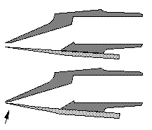
Knowing that we must approach the digital synthesis of the sound from both time-based and frequency-based, I started from analyzing the time-based aspect of a saxophone sound. Below are the time-based response of three different type of instruments (woodwind, bell, drum):
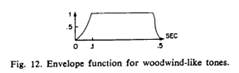
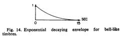
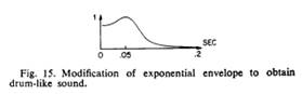
As expected, the bell has a very sharp attack and an exponential like decay. The envelope I am interested in is the woodwind-like one, since a saxophone falls in the category of woodwind instruments. Thus, the amplitude of overall digital signal I produce would have an exponential rise, a steady hold value, and a smooth but quick exponential decay.
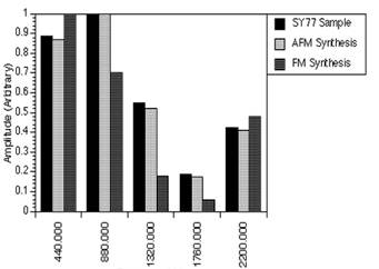
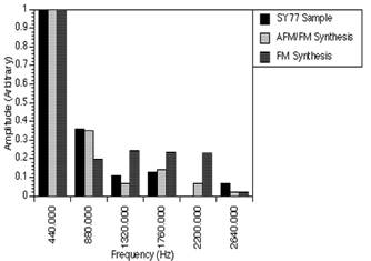
The next aspect is the frequency spectrum. Below is the analysis of four instruments, the saxophone, harp, bassoon, and pipe organ for comparison:
Saxaphone
Harp
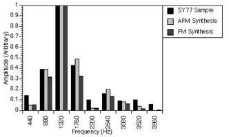
Bassoon
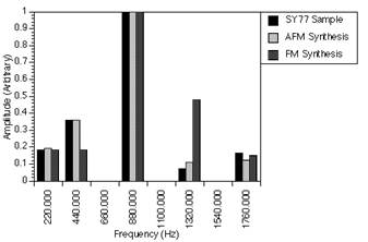
Pipe organ
All these notes are played at 440Hz. The other bars represent the harmonics (integer multiples of the frequency of the desired note) around the 440 Hz note. This is a normalized representation, as you see the highest amplitude is equal to one, thus you can scale your own amplitudes simply to the ratios. For the saxophone we see that the first and second harmonics are strongest but, there are also 3rd, 4th and 5th harmonics. As I discovered during testing of the sound, these additional harmonics are crucial in contributing to the overall saxophone sound despite their smaller amplitudes.
Hardware and Software Design
Mouthpiece:
The mouthpiece of a saxophone is the source of the sound produced. Below is a dissection of the mouthpiece. On the bottom there is a thin piece of wood called the reed. As the player blows into the mouthpiece and apply pressure to the reed, the reed will vibrate in a way that allows airflow into the mouthpiece to resonate in a sin-wave like fashion. This vibration along with opening and closing holes on the side of the saxophone produces the different tones at their corresponding frequencies.
Mouthpiece of an actual saxophone
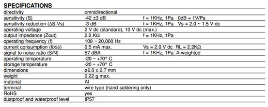
To simulate this sound we needed a device that could sense the player blowing. Thus we used a microphone for this purpose. The microphone will input the user’s blow whereas the microcontroller will take care of the sound producing algorithm.
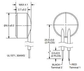
Dimensions of the microphone
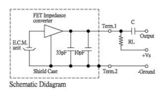
Measurement Circuit
Since the microphone is omnidirectional, noise from all directions surrounding it will all be taken in by it. To isolate the player’s blow I made a cone shaped shield around the microphone as shown below:
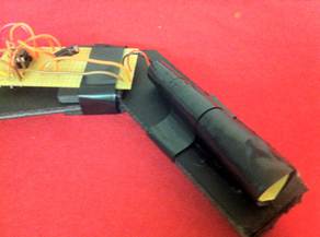
Image of the mouthpiece
Because the microphone’s output is in the range of millivolts, we must amplify this signal before we feed it into the microcontroller’s ADC. To achieve this, the following circuit called the pre-amp is built shown below (the above image also shows the preamp connecting to the microphone which is at the back tip of the cone).
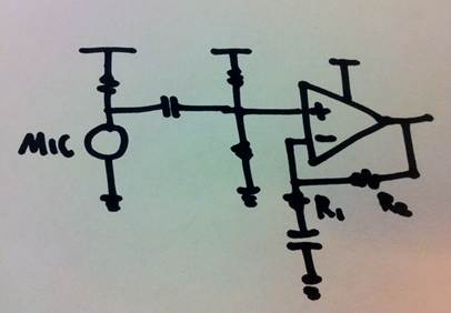
Pre-amp for the microphone
The resistor above the microphone sets the bias current needed. I chose a 3.1kOhms bias resistor on top of the microphone for a 4.1V operating voltage well below the 10V maximum. A large AC-coupling capacitor (1 uH) follows the microphone stage to separate its bias point with the pre-amp’s. The pre-amp’s bias is set by the dual resistor which is both 5.1 kOhms to place the bias at half of Vdd, which is 2.5V. This is a non-inverting configuration with a gain of R2/R1. The amplifier I used is the LM358. I chose R2 to be 1MOhms and R1 to be 10kOhms for a gain of 100. This way the small signal output of the microphone can be amplified enough for the microcontroller’s ADC to read.
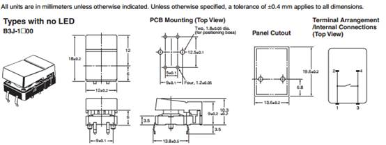
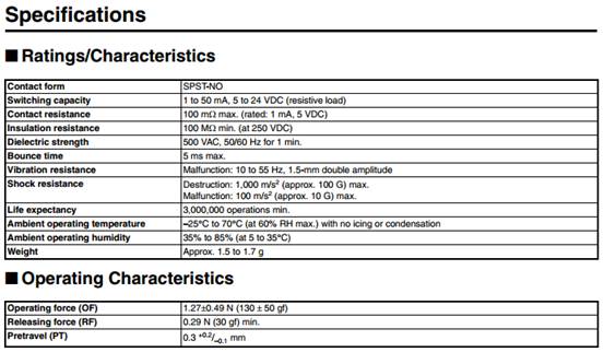
Buttons:
In an actual saxophone the buttons open and close holes that will alter the standing waveforms within the body and thus changing the frequency of the tone. In this digital saxophone, the button locations are designed to match the actual saxophone while the sound production is managed by the microcontroller. The specifications of the button are below. The pins on the microcontroller are configured to input with pull-up resistors on. The buttons are connected one end to ground and the other end to a pin each. When the button is pressed it will short the ground side and the pin side together. Thus when un-pushed the pins are high, and when pushed they are ground. A table of different key configurations is set in the software so the microcontroller will produce the sound that corresponds to the buttons you’ve pushed.
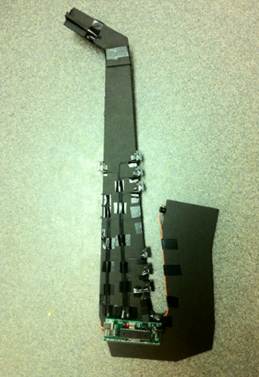
The image bellow is a close-up of the buttons where one side is connected to a pin each and the other is connected to the ground.
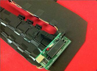
Wiring of buttons to the microcontroller
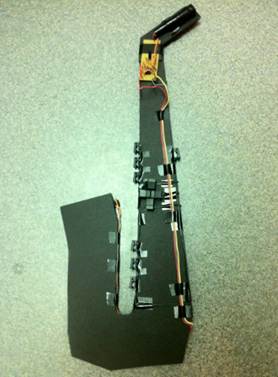
The two images below show the left and right side of the saxophone:
Software:
The software processes the inputs from the microphone and the pushbuttons and produces the sound through an additive synthesis algorithm. Below are a summary of the important tasks and functions.
àTimer0 is used to control the Pulse Width Modulator (PWM):
TCCR0B = 1; //timer 0 runs at full rate
TIMSK0 = 0; //turn off timer 0 overflow ISR TCCR0A = (1<<COM0A0) | (1<<COM0A1) | (1<<WGM00) | (1<<WGM01); //turn on PWM, turn on fast PWM and OC0A output at full clock rate, toggle OC0A (pin B3) 16 microsec per PWM cycle sample timeOCR0A = 128; //set PWM to half full scale
This code allows the PWM to output pulses at pin B.3 according to the synthesis code, which produces voltages relative to how wide a high pulse is compared to a low pulse width.
àTimer1 is used to run the Sound synthesis at 8kHz rate:
// timer 1 ticks at 8000 Hz or 125 microsecs period=2000 ticks
OCR1A = 1999; //2000 ticks TIMSK1 = (1<<OCIE1A); TCCR1B = 0x09; //full speed; clear-on-matchTCCR1A = 0x00; //turn off pwm and oc lines
àTask0 measures the voltage out from the pre-amp with the microcontroller’s ADC:
void task0(void)
begin
DDRA=0; //port
A is an input
ADMUX = (1<<ADLAR) | (1<<REFS0); //5V ref
ADCSRA = (1<<ADEN) + 7; //enable ADC and set prescaler
1/128*16MHz = 125MHz
if(!(ADCSRA &
(1<<ADSC))) ADCSRA|=(1<<ADSC);
Ain = ADCH;
end
àThe following is the definitions for the fundamental frequencies of each note and their corresponding keys:
float frequencies[13] = {65.41, 69.41,
73.42, 77.78, 82.41, 87.31, 92.50, 98.00, 103.83, 110.00…
// C
C#
D D# E
F F# G G# A …
unsigned char keyC[13]
={0xFD, 0xFD, 0xFC, 0xFE, 0xF8, 0xF0, 0xE8, 0xE0, 0xE0, 0xC0, 0x90,…
àSince there are a total of 13 buttons, pins from both port C and D are used. The first key corresponding to pressing PINC.1 is matched to the first frequency 65.41 Hz. The code below basically checks if the value that the ADC reads suggests that the player has blown into the mouthpiece. The for-loop then checks which of the button configuration is pressed. Then if there was previously no blow, then the sound production starts. The fall_all = 50 (the larger the value the longer the decay) makes the decay very very slow, which will let the note hold until Ain returns the value where the microphone senses no blow.
if(Ain >
135 || Ain < 115) begin
keyPressedC
= ~PINC;
keyPressedD
= ~PIND;
if (keyPressedC & 0xff) begin
for(j = 0; j
<= 12; j++) begin
if((keyC[j] == keyPressedC)
&& (keyD[j] == keyPressedD))
begin
index = j;
if(!blowed) begin
pluck = 1;
blowed = 1;
fall_all =
50;
end
end
end
end
end
àThe code below is the sound parameters that determine the digital synthesis of each note. For the details of the digital synthesis algorithm refer to the code section in the end of the report. This code only includes the first two harmonics, as you see that inc_2 has a frequency that is 2 times that of the fundamental from inc_1. All the fall parameters are set to fall_all so that when a player is blowing fall_all is set to a high value to hold the note, and when the blowing stops fall_all is set to a low value and the note fades. Also the amplitude of each harmonics is reflected by the coefficient for max_amp, as they are 1, 0.8, 0.5, 0.2, 0.4 corresponding to the frequency-based analysis done earlier.
inc_1
= (int)(8.192 *
frequencies[index]) ; // sets the
frequency of the sin wave
// rise and decay SHIFT factors -- bigger is
slower -- max value is 8
fall_1 = fall_all ;
rise_1 = 2 ;
a_1 = 7 ; // amplitude SHIFT
factor -- bigger is lower amp -- min
value is 7
sel_1 = sine ;
max_amp1 = 32767 * 1; //maximum amplitude when note is played
inc_2 = (int)(8.192
* frequencies[index] * 2) ;
fall_2 = fall_all ;
rise_2 = 2 ;
a_2 = 7 ;
sel_2 = sine ;
max_amp2 = 32767 * 0.8;
Results
The digital saxophone was able to successfully produce the notes that were played as the user blows into the microphone. The image below shows how the output of the pre-amp is boosted when the microphone senses a pressured blow from the user and outputs a small voltage difference.
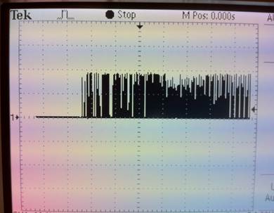
Oscilloscope display of the microphone output after pre-amp
Conclusion
This project incorporated many concepts acquired from the labs that we have done for this class, including voltage measurement with the ADC and digital sound synthesis. I was able to further explore techniques in sound synthesis by producing richer instrumental sounds with multiple harmonics in comparison to the lab which only used FM synthesis.
Through the process of building this project as well as seeing other groups create theirs, I realized the vast capabilities of a microcontroller with the variety of peripherals one can find and buy online. This project, although straightforward and easy to implement, gives a good idea of the length, effort, and issues in putting together a microcontroller based product. It will be a good stepping stone to more advanced projects in the future.
Reference
[1] John C. “The Synthesis of Complex Audio Spectra by Means of Frequency Modulation,” Journal of the Audio Engineering Society.
[2] Analysis of AFM Real-time Synthesis Results, http://xenia.media.mit.edu/~gan/Gan/Education/NUS/Physics/MScThesis/Chapter8.html
[3] Bruce Land, ECE 4760 Webpage, Lab 3, http://people.ece.cornell.edu/land/courses/ece4760/labs/s2012/lab3.html
Appendices
Parts list and cost
|
Name |
Supplier |
Unit cost |
Quantity |
Total cost |
|
Microcontroller |
ECE 4760 lab (Atmel 644) |
$6.00 |
1 |
$6.00 |
|
Microphone |
ECE 4760 lab |
$2.62 |
1 |
$2.62 |
|
Pushbutton |
DigiKey (SW820-ND) |
$1.81 |
13 |
$23.53 |
|
Op-amp |
ECE 4760 lab (LM358) |
$0.45 |
1 |
$0.45 |
|
Foam board |
Cornell Store |
$11.99 |
1 |
$11.99 |
|
Total |
$44.59 |
|||
CODE:
//
DDS output thru PWM on timer0 OC0A (pin B.3)
//
Mega644 version
//
additive synthesis
#include
<inttypes.h>
#include
<avr/io.h>
#include
<avr/interrupt.h>
#include
<math.h> //
for sine
#include
<stdlib.h> //
for rand
#include
<stdio.h>
#include
"uart.h"
//
set up serial for debugging
FILE uart_str = FDEV_SETUP_STREAM(uart_putchar, uart_getchar,
_FDEV_SETUP_RW);
//I
like these definitions
#define
begin {
#define
end }
#define
max_amp 32767
//
masks for random noise shift register
// 32
bits
//
http://en.wikipedia.org/wiki/Linear_feedback_shift_register
#define
bit15 0b0100000000000000
#define
bit14 0b0010000000000000
volatile unsigned int
noise_gen ;
char bit0, bit1 ; // linear feedback
bits
//
The DDS variables
volatile unsigned int
acc_1, acc_2, acc_3, acc_4, acc_5 ;
volatile unsigned int
inc_1, inc_2, inc_3, inc_4, inc_5 ;
volatile unsigned char high_1, high_2,
high_3, high_4, high_5 ;
//
attack and decay constants
volatile unsigned char rise_1, rise_2,
rise_3, rise_4, rise_5, rise_n ;
volatile unsigned char fall_1, fall_2,
fall_3, fall_4, fall_5, fall_n, fall_all
;
//
attack and decay waveforms
volatile int
amp_rise_1, amp_rise_2 ,amp_rise_3, amp_rise_4, amp_rise_5, amp_rise_n
;
volatile int
amp_fall_1, amp_fall_2 ,amp_fall_3, amp_fall_4, amp_fall_5, amp_fall_n
;
volatile int
max_amp1, max_amp2, max_amp3, max_amp4, max_amp5;
//
amplitude waveforms = attack * decay waveforms
volatile int
amp_1, amp_2 ,amp_3, amp_4, amp_5, amp_n ;
//
amplitude scaling constant
volatile unsigned char a_1, a_2, a_3,
a_4, a_5, a_n ;
//
tables for DDS and the output waves to be added together
volatile signed char wave_table[3][256],
sine_1, sine_2, sine_3, sine_4, sine_5, noise ;
volatile unsigned char sel_1, sel_2,
sel_3, sel_4, sel_5 ;
#define
sine 0
#define
saw 1
#define
tri 2
//
trigger state variables
volatile char pluck, blowed;
//
Time variables
//
the volitile is needed because the time is only set
in the ISR
//
time counts mSec, sample counts DDS samples (62.5
KHz)
volatile unsigned char time ;
volatile char count;
//
index for sine table build
unsigned int i, j;
float frequencies[13] = {65.41, 69.41,
73.42, 77.78, 82.41, 87.31, 92.50, 98.00, 103.83, 110.00, 116.54, 123.47,
130.81};
C C# D D# E
F F# G
G#
A A# B
C
unsigned int
index;
unsigned char keyC[13]
={0xFD,
0xFD,
0xFC,
0xFE,
0xF8,
0xF0,
0xE8,
0xE0,
0xE0,
0xC0,
0x90,
0x80,
0x40};
unsigned char keyD[13]
={0x00,
0x02,
0x00,
0x00,
0x00,
0x00,
0x00,
0x00,
0x04,
0x00,
0x00,
0x00,
0x00};
unsigned char keyPressedC;
unsigned char keyPressedD;
#define
t0 1
volatile unsigned char time0
void task0(void);
void initialize(void);
char Ain;
char tally;
/////////////////////////////////////////////////////////
//timer
0 compare ISR
ISR
(TIMER2_COMPA_vect)
begin
if (time0>0) --time0;
end
/////////////////////////////////////////////////////////
ISR
(TIMER1_COMPA_vect) // Fs = 8000
begin
// turn on timer for
profiling
TCNT2 = 0; TCCR2B = 2;
// compute exponential
attack and decay of amplitude
// the (time & 0x0ff)
slows down the decay computation by 256 times
if
((time & 0x0ff) == 0) begin
amp_fall_1
= amp_fall_1 - (amp_fall_1>>fall_1) ;
amp_rise_1
= amp_rise_1 - (amp_rise_1>>rise_1);
amp_fall_2
= amp_fall_2 - (amp_fall_2>>fall_2) ;
amp_rise_2
= amp_rise_2 - (amp_rise_2>>rise_2);
amp_fall_3
= amp_fall_3 - (amp_fall_3>>fall_3) ;
amp_rise_3
= amp_rise_3 - (amp_rise_3>>rise_3);
amp_fall_4
= amp_fall_4 - (amp_fall_4>>fall_4) ;
amp_rise_4
= amp_rise_4 - (amp_rise_4>>rise_4);
amp_fall_5
= amp_fall_5 - (amp_fall_5>>fall_5) ;
amp_rise_5
= amp_rise_5 - (amp_rise_5>>rise_5);
//amp_fall_n = amp_fall_n - (amp_fall_n>>fall_n) ;
//amp_rise_n = amp_rise_n - (amp_rise_n>>rise_n);
end
// form (1-exp(-t/tau)) for the attack phase
// product of rise and fall
exponentials is the amplitude envelope
amp_1 = ((max_amp1 -
amp_rise_1)>>8) * (amp_fall_1>>8) ;
amp_2 = ((max_amp2 -
amp_rise_2)>>8) * (amp_fall_2>>8) ;
amp_3 = ((max_amp3 -
amp_rise_3)>>8) * (amp_fall_3>>8) ;
amp_4 = ((max_amp4 -
amp_rise_4)>>8) * (amp_fall_4>>8) ;
amp_5 = ((max_amp5 -
amp_rise_5)>>8) * (amp_fall_5>>8) ;
//amp_n
= ((max_amp - amp_rise_n)>>8)
* (amp_fall_n>>8) ;
// Init
the synth
if
(pluck==1) begin
amp_fall_1
= max_amp1;
amp_rise_1
= max_amp1;
amp_fall_2
= max_amp2;
amp_rise_2
= max_amp2;
amp_fall_3
= max_amp3;
amp_rise_3
= max_amp3;
amp_fall_4
= max_amp4;
amp_rise_4
= max_amp4;
amp_fall_5
= max_amp5;
amp_rise_5
= max_amp5;
//amp_fall_n = max_amp;
//amp_rise_n = max_amp ;
acc_1 =
0 ; //
phase lock the synth
acc_2 =
0 ;
acc_3 =
0 ;
acc_4 =
0 ;
acc_5 =
0 ;
pluck = 0;
end
//the DDRs --
acc_1 = acc_1 + inc_1 ;
high_1 = (char)(acc_1 >> 8) ;
sine_1 = (signed char)((((amp_1>>8) * (int)wave_table[sel_1][high_1]))>>a_1) ;
acc_2 = acc_2 + inc_2 ;
high_2 = (char)(acc_2 >> 8) ;
sine_2 = (signed char)((((amp_2>>8) * (int)wave_table[sel_2][high_2]))>>a_2) ;
acc_3 = acc_3 + inc_3 ;
high_3 = (char)(acc_3 >> 8) ;
sine_3 = (signed char)((((amp_3>>8) * (int)wave_table[sel_3][high_3]))>>a_3) ;
acc_4 = acc_4 + inc_4 ;
high_4 = (char)(acc_4 >> 8) ;
sine_4 = (signed char)((((amp_4>>8) * (int)wave_table[sel_4][high_4]))>>a_4) ;
acc_5 = acc_5 + inc_5 ;
high_5 = (char)(acc_5 >> 8) ;
sine_5 = (signed char)((((amp_5>>8) * (int)wave_table[sel_5][high_5]))>>a_5) ;
/*
// add some noise
noise_gen
= noise_gen << 1 ;
// & with bit 30 for
'linear feedback shoft register'
bit0 = (noise_gen
& bit15)>0 ;
// & with bit 27
bit1 = (noise_gen
& bit14)>0 ;
noise_gen
= noise_gen + (bit0 ^ bit1) ;
//noise = (signed char)((((amp_n>>8) * (int)noiseTable[(unsigned
char)time]))>>a_n) ;
noise
= (signed char)((((amp_n>>8) * (int)(noise_gen &
0xff)))>>a_n) ;
*/
// output the wavefrom sample
// scale amplitude to use
only high byte and shift into range
// 0 to 255
OCR0A = 128 + sine_1 +
sine_2 + sine_3 + sine_4 + sine_5 ;//+ noise ;
time++; //ticks at 8 KHz -- maxvalue
255
// profiling
TCCR2B = 0;
end
/////////////////////////////////////////////////////
int
sound(void)
begin
// frequency 2^16/8000*freq
= 8.192*freq
inc_1 = (int)(8.192 * frequencies[index]) ;
//fall_1 = 5 ; // rise and
decay SHIFT factors -- bigger is slower
-- max value is 8
fall_1 = fall_all ;
rise_1 = 2 ;
a_1 = 7 ; //
amplitude SHIFT factor -- bigger is
lower amp -- min value is 7
sel_1 = sine ;
max_amp1 = 32767 * 1;
inc_2 = (int)(8.192
* frequencies[index] * 2) ;
//fall_2 = 5 ;
fall_2 = fall_all ;
rise_2 = 2 ;
a_2 = 7 ;
sel_2 = sine ;
max_amp2 = 32767 * 0.8;
inc_3 = (int)(8.192
* frequencies[index] * 3) ;
//fall_3 = 5 ;
fall_3 = fall_all ;
rise_3 = 2 ;
a_3 = 7 ;
sel_3 = sine ;
max_amp3 = 32767 * 0.2;
inc_4 = (int)(8.192
* frequencies[index] * 4) ;
//fall_4 = 5 ;
fall_4 = fall_all ;
rise_4 = 2 ;
a_4 = 7 ;
sel_4 = sine ;
max_amp4 = 32767 * 0.4;
inc_5 = (int)(8.192
* frequencies[index] * 5) ;
//fall_5 = 5 ;
fall_5 = fall_all ;
rise_5 = 2 ;
a_5 = 7 ;
sel_5 = sine ;
max_amp5 = 32767 * 0.2;
/* noise
fall_n = 2 ;
rise_n = 0 ;
a_n = 7 ;
noise_gen = 4 ;*/
end
/////////////////////////////////////////////////////
//Task
0 - Get Voltage
void task0(void)
begin
DDRA=0; //port
A is an input
ADMUX = (1<<ADLAR) | (1<<REFS0); //5V ref
ADCSRA = (1<<ADEN) + 7; //enable ADC and set prescaler 1/128*16MHz = 125MHz
if(!(ADCSRA &
(1<<ADSC))) ADCSRA|=(1<<ADSC);
Ain = ADCH;
end
/////////////////////////////////////////////////////
int
main(void)
begin
// make B.3 an output
DDRC = 0x00;
PORTC = 0xFF;
DDRD = 0x00;
PORTD = 0xFF;
DDRB = (1<<PINB3) ;
//init the UART --
uart_init()
is in uart.c
uart_init();
stdout = stdin
= stderr = &uart_str;
fprintf(stdout,"Starting...\n\r");
//srand(99);
// init the sine, sawtooth, trigangle wave table
for (i=0; i<256; i++)
begin
wave_table[sine][i] = (char)(127.0 * sin(6.283*((float)i)/256.0))
;
wave_table[saw][i] = (char)(( (i<17)? i*7 : (i<241)? 128-i : i*7-1792 )) ;
wave_table[tri][i] = (char) (( (i<64)? i : (i<192)? 128-i : i-256 )) ;
//printf("%d\n\r",
wave_table[tri][i]);
end
// init the time
counter
time=0;
// timer 0 runs at full rate
TCCR0B = 1 ;
//turn off timer 0 overflow
ISR
TIMSK0 = 0 ;
// turn on PWM
// turn on fast PWM and OC0A output
// at full clock rate, toggle OC0A (pin B3)
// 16 microsec per
PWM cycle sample time
TCCR0A = (1<<COM0A0) |
(1<<COM0A1) | (1<<WGM00) | (1<<WGM01) ;
OCR0A = 128 ; //
set PWM to half full scale
// timer 1 ticks at 8000 Hz or 125 microsecs period=2000 ticks
OCR1A = 1999 ; //
2000 ticks
TIMSK1 = (1<<OCIE1A)
;
TCCR1B = 0x09; //full speed; clear-on-match
TCCR1A = 0x00; //turn off pwm and oc
lines
// turn on all ISRs
sei() ;
////////////////////////////////////////////////////
while(1) begin
if (time0==0){ time0=t0; task0();}
if (time == 200) begin
if(Ain > 135 || Ain < 115)
begin
keyPressedC
= ~PINC;
keyPressedD
= ~PIND;
if (keyPressedC & 0xff) begin
for(j = 0; j
<= 12; j++) begin
if((keyC[j] == keyPressedC)
&& (keyD[j] == keyPressedD))
begin
index = j;
if(!blowed) begin
pluck = 1;
blowed = 1;
fall_all
= 50;
end
end
end
end
end
if ((Ain > 135 || Ain <
115) && blowed)
tally=0;
if ((Ain <= 135 || Ain
>=115) && blowed)
begin
tally++;
if(tally > 10)
begin
tally = 0;
blowed
= 0;
fall_all = 5;
end
end
sound();
time = 0;
end //while
end //end
main
/////////////////////////////////////////////////////////////