Customer's Voice top
“Hello,
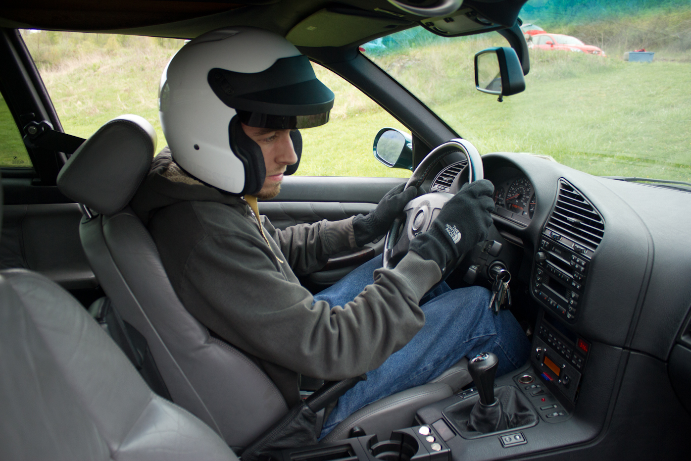
I am interested in a race car logger than will be able to display and log crucial information during autocross and track events. I am interested in tracking vehicle speed, RPM, engine coolant temperature and lateral g-forces. Ideally, the data can be stored on a SD card which can later be read on a computer. An LCD display showing two or more parameters will be extremely useful during the events so the status of the car can be determined in real time. The car that this will be used in is a 1997 E36 M3.
Best,
Jay“

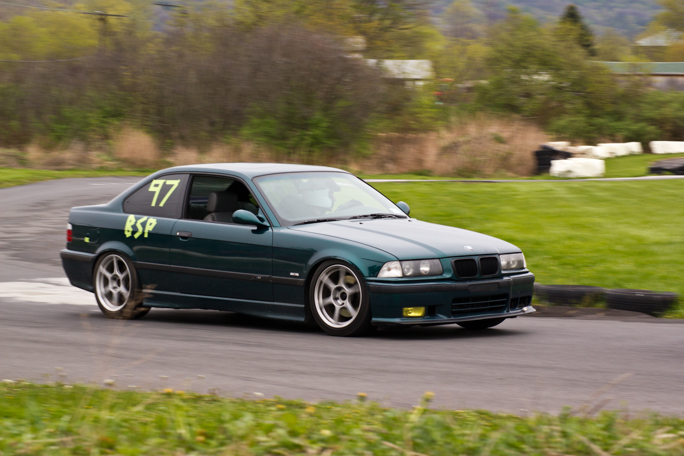
1997 BMW E36 M3 at an AutoCross.
Abstract top
The TrckrX is an On-Board-Diagnostics (OBD-II) compliant device that provides the driver with instantaneous vehicle speed, RPM and coolant temperature. The above mentioned parameters are displayed on a LCD. In addition, few extra parameters such as a time stamp and lateral g-force are stored on a SD card.
Autocross is a form of motorsports that emphasizes active participation and at the same time safe competition since there is only one car on the course during a run. This is what makes it different from road racing or oval racing. There are no wheel-to-wheel racing and no physical obstacles which constitutes for low potential of car damage. This is one of the main reasons why most participants take their “daily drivers” to autocross events. It is considered as an inexpensive sport. Car clubs reduce the entry barriers further by introducing different classes. Autocross is an entry level motorsport which provides a stepping stone for drivers looking to move into other more competitive and possibly expensive forms of motorsport including rally and circuit racing where vehicle specifications are even higher.
In North America, autocross events are usually held in large paved areas like parking lots or airfields. Usually, new courses are created for each event so drivers must learn a new course each time they compete. National organizations such as the Sports Car Club of America (SCCA) and National Auto Sport Association (NASA) sponsor autocross events throughout the United States.
For this objective, TrckrX is an ideal aid for the average autocross participant who wants to monitor his vehicle real-time and then analyze it further with the aid of computational and graphing software such as Excel. The OBD-II standard provides access to numerous sensors that the vehicle uses to maintain proper functionality. TrckrX is able to utilize that and an additional accelerometer sensor to measure lateral acceleration.
Background
In the beginning of the 1970’s, in order to comply with the Environmental Protection Agency (EPA) emission standards, manufacturers turned to electronically controlled fuel feed and ignition systems. Sensors measured engine performance and adjusted the systems to provide minimum pollution. These sensors were also accessed to provide early diagnostic assistance. This was the dawn of on-board diagnostics (OBD). Through the years OBD systems have become more sophisticated and in 1996 the Society of Automotive Engineers (SAE) established a standard connector plug (Figure 1) and set of diagnostic test signals. This became known as OBD-II.

Figure 1. J1962 Connector Plug
Diagnostics have found value in vehicle servicing and repairs. Diverse diagnostic techniques are used in production line vehicles. There are currently five signaling protocols in use with the OBD-II interface. Every vehicle has one of these protocols. It is often possible to determine the specific protocol by merely examining the pin-out of the J1962 connector or by knowing the vehicle’s manufacturer.
In order to communicate over OBD-II, all devices use Parameter IDs (PID) requests to retrieve the needed information. PID codes are part of SAE standard J1979, which was implemented in all cars sold in North America since 1996. There are ten modes of operation in the latest OBD-II standard.
There are three major parts in the design of the TrckrX project that needed to be addressed. The first module is the OBD-II vehicle, followed by an OBD-II compliant reading chip. Lastly, analyzing and displaying of the information to driver is implemented using an Atmel 8-bit ATmega644 microcontroller and a LCD.
Vehicle
The TrckrX requires the OBD-II standard making it complaint to vehicles manufactured after 1996. Although five different signal protocols exist all cars since 2008 in North America use the ISO 15765 CAN bus signal protocol, minimizing the likelihood of encountering the other four protocols. During the developing of the TrckrX an ECU simulator board will be introduced, the ISO 15765-4 ECUSim 2000 OBD-II Simulator from OBD Solutions.

Figure 2. ISO 15765-4 ECUSim 2000
The project was designed and tested to work on BMW’s OBD-II Signal Protocol – ISO 9141. The specific car model is E36 BMW M3.
Communication Integrated Circuit
There are various off-the-shelf OBD-II communication integrated circuits. The TrckrX is utilizing microOBD 200 (PIC24 microcontroller) which is designed around the STN1120. MicroOBD 200 is a quick and easy way to add OBD support to any project. The STN11xx chip itself is an enhanced version of the popular ELM327 chip. It is the world’s smallest, lowest cost multiprotocol OBD to UART interpreter IC. It provides an easy means of accessing hundreds of real-time parameters. The STN1110 outperforms the original ELM327 IC in every category: stability, performance, and features.
Data Acquisition and Display
The final, and most essential, feature of the project is the actual processing and display of the received information. For this purpose, the ATmega644 MCU is utilized. It handles the communication between the vehicle’s ECU via the OBD-II interpreter IC. The communication is done over UART. In addition, to reading all the specific PID codes for vehicle speed (VSS), RPM, engine coolant temperature an external accelerometer was added. It provided readings of lateral acceleration. The MCU also handles the logging of the data on a SD card in format that can be easily read on a personal computer.

Figure 3. TrckrX Block Diagram
Hardware and Software Design top
The development of the TrckrX started with ordering all the necessary components. Some parts were already present; other still had to be ordered. The microOBD 200 IC and the ECU simulator were available since my MEng project shared the same components and with the permission of Pr. Land, I was able to incorporate the two into my work. Although I had sufficient previous experience with the OBD-II standard, making the UART communication between the ATmega 644 and the microOBD IC to work was not an easy task. Thanks to Avi Aisenberg and Mike Andromalos, and their OBD-II project in ECE 4760 back in 2009, this task was a bit simplified.
The whole project was designed incrementally. First phase was the OBD communication followed by the accelerometer readings. Last was the SD card logging.
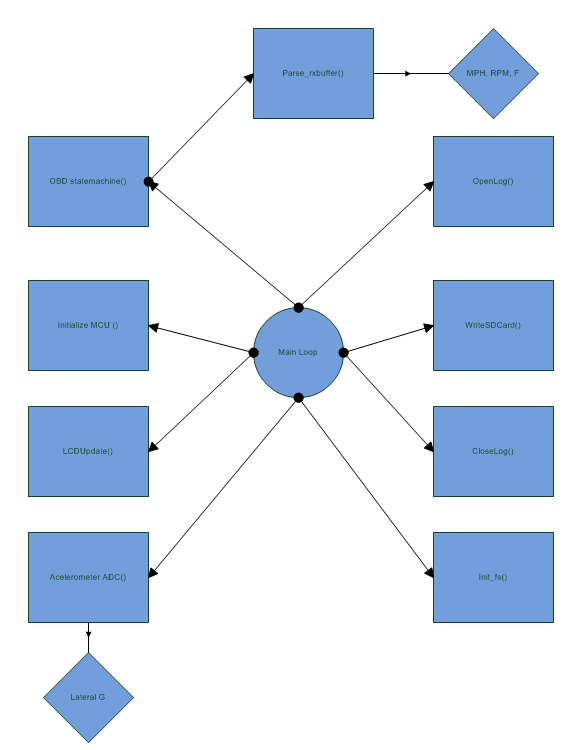
Figure 4. State Machine
Most challenging of all was to setup the two microcontrollers to communicate synchronously at the correct baud rate, followed by the SD card logging.
It turned out that the OBD-II communication has to run at full rate i.e. 16Mhz for the standard crystal used in ECE 4760. Otherwise the response characters will not be read properly and the system will stall. In addition, a set of software filters were developed to distinguish the responses from the ECU.
The principle behind OBD-II communication is pretty straightforward. A OBD-II device sends a request to the vehicle ECU called Parameter-ID (PID) code and receives a response right back. There are different modes of PIDs but the one the TrckrX is focused on is real-time data. A PID code by its nature is a combination of HEX numbers and the response is also in HEX. Some PID codes like MAF, RPM and coolant temperature are in two byte response where vehicle speed is a single byte value from 0 to 255. For more information on PID codes visit this Wikipedia article.
After that milestone was completed, the rest was pretty straight forward as far as data extraction goes. The accelerometer used was MMA1260D, which was extensively used by many other projects in the class and setting it up was not an issue. Initially a separate code was developed which only took a peak “g” value.
The SD card interface took a substantial amount of debugging time. It utilizes FatFS file system which is essentially a FAT16. The advantages are that it has much less overhead compared to FAT32 and works straight forward with the AVR architecture.
Thanks to the numerous project that have used SD card logging and the creator of the FatFS, I was able to fully understand the theory behind the software and the hardware interface. However the later wasn’t so straightforward. After several hours (read triple digit hours) of testing and trying out different circuits, I arrived at the conclusion that the LM2951 voltage regulator 3.3V is causing the whole circuit to go out of spec. It was proven that the LM2951 destroys PIN B.4 which is the chip select (CS) for the SPI mode to the extent that you can use straight wires and power your SD card with 5V. It seemed like the Snorerecorder from Jimmy Da and Aaron Meller has experienced the same exact problem.
Due to the fact that I was aiming for early finish of the project, mainly because we had an Autocross event 2 weeks earlier than my demo slot, I had to have the device ready for April 22nd!
Once this module was complete it was time to put the whole source code together. This part wasn’t hard at all since all the components were working independently and it was a matter of time to put them together to produce the TrckrX. The state flow diagram below represents the source code.
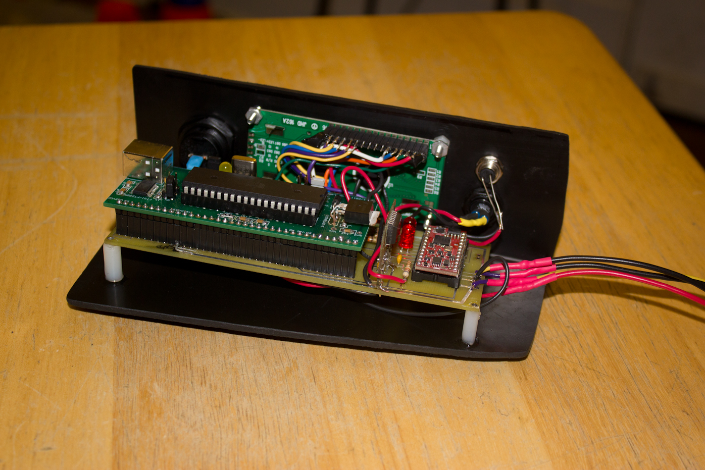
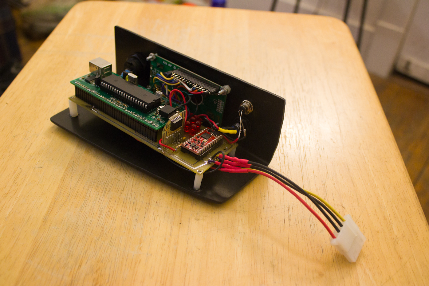
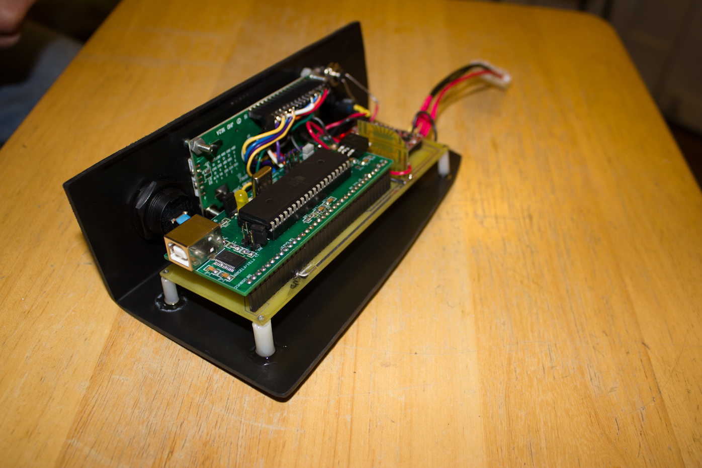
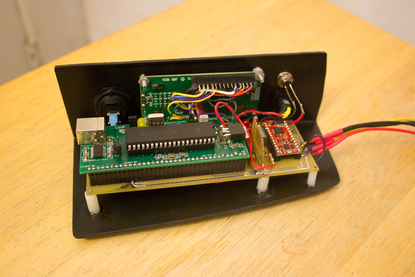
In addition a PCB layout was designed using ExpressPCBs services.
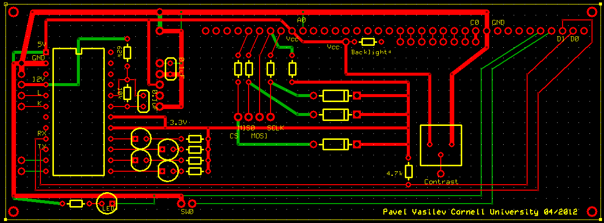
Figure 5. TrckrX PCB Layout
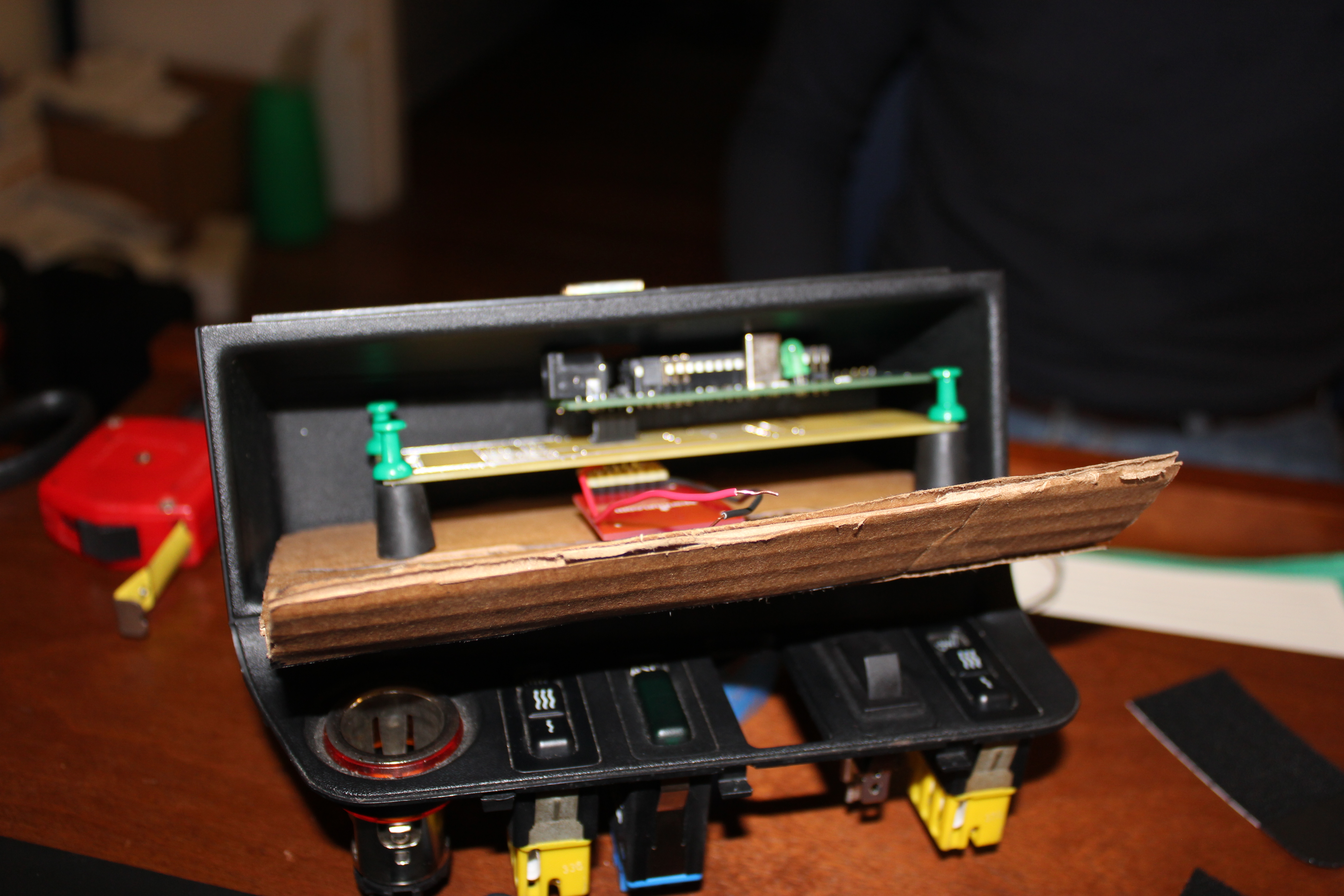
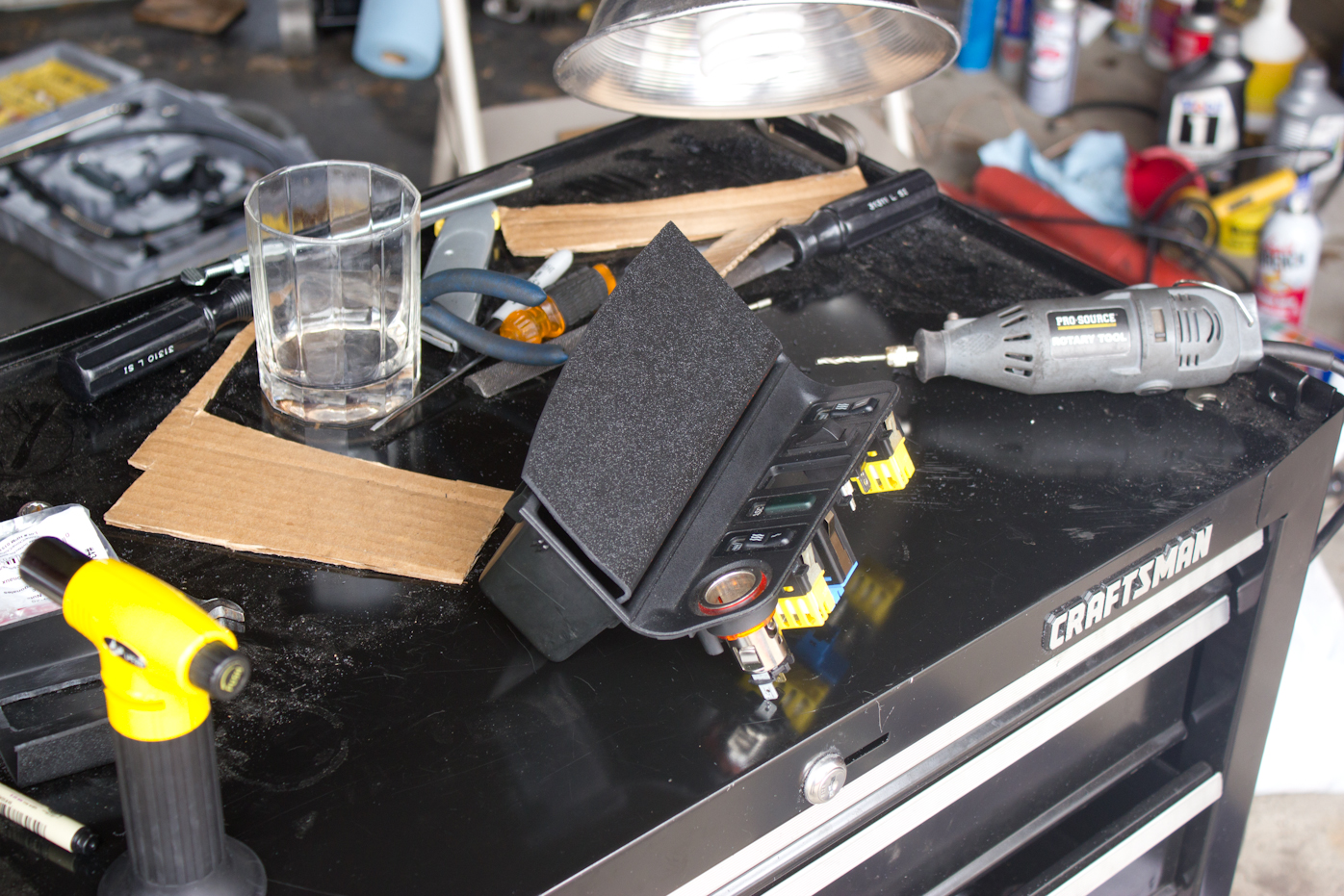
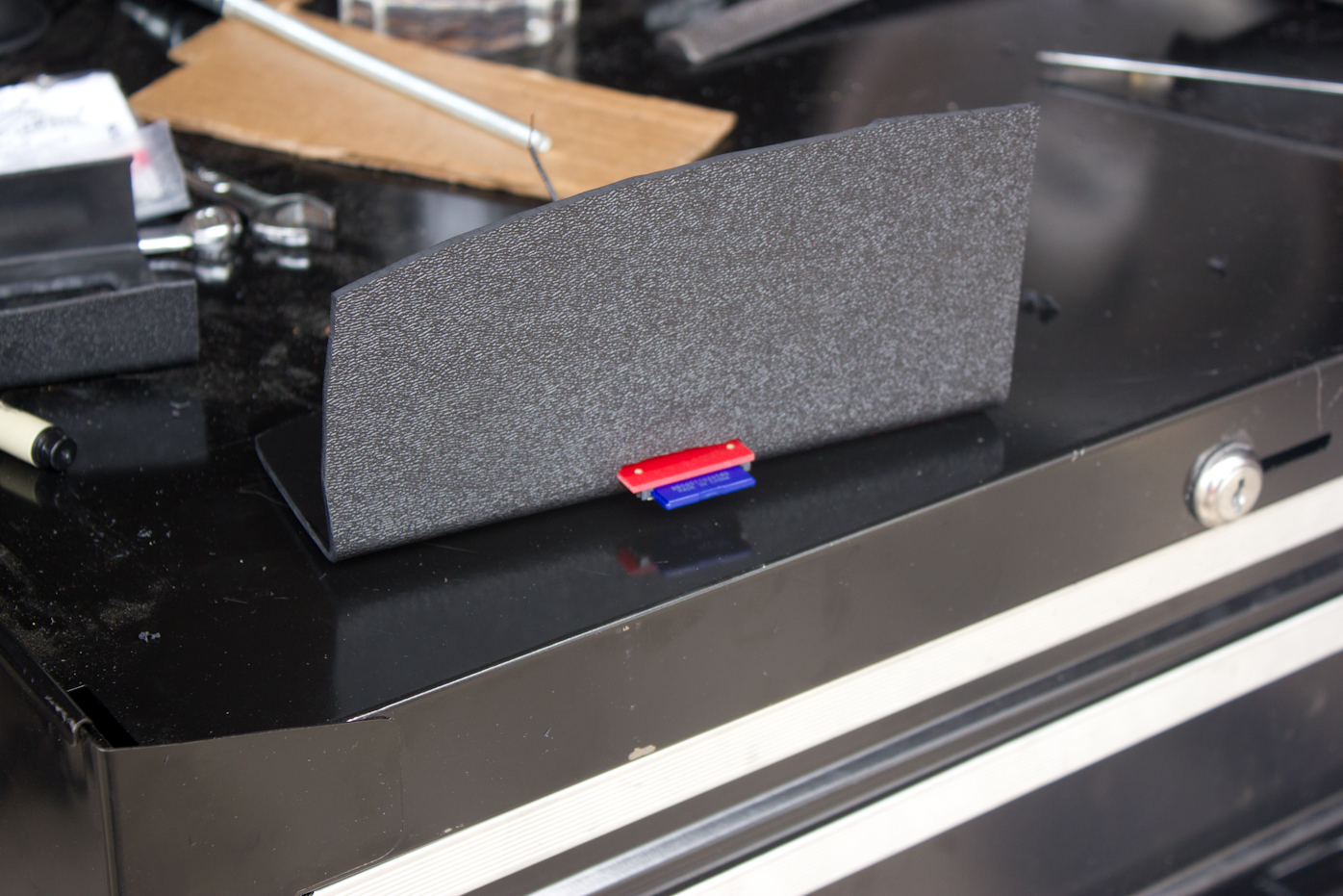
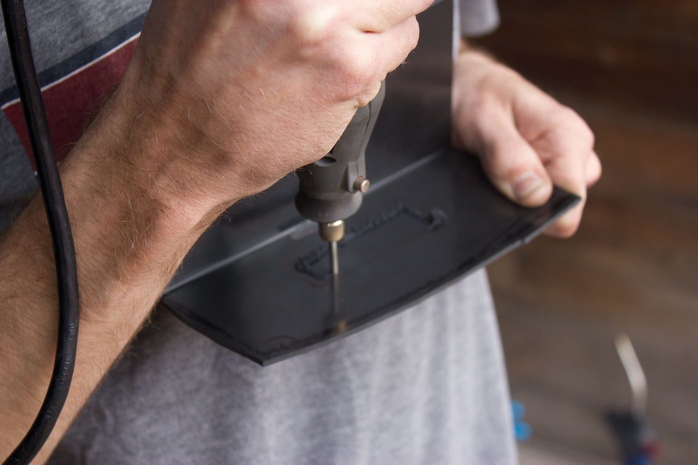
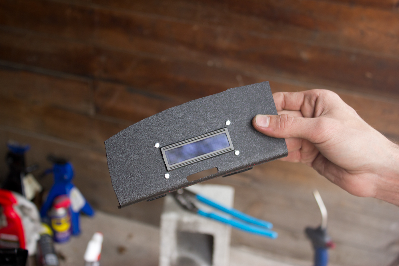
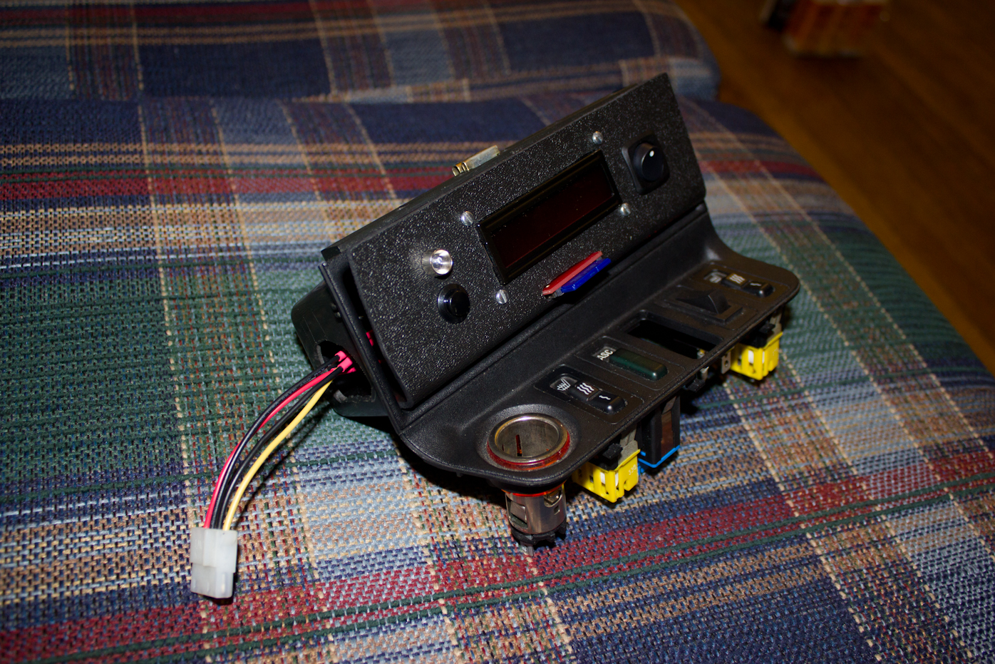
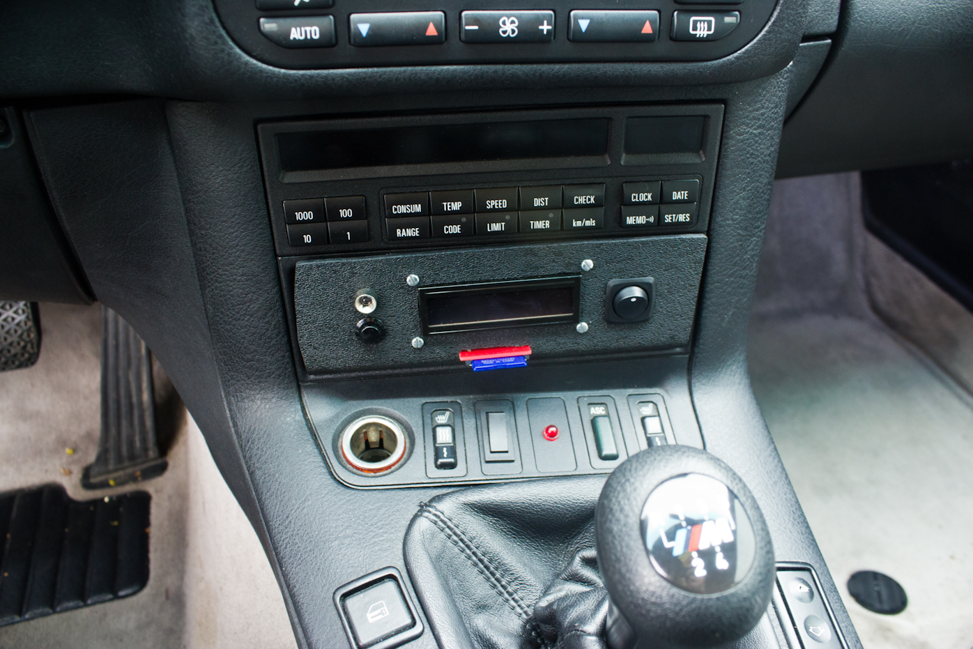
While developing the hardware and the software, there was another important task myself and my customer (Jay) imposed to us. That was to make the device to look completely stock inside his BMW. After several hours of brain storming we decided to go for a custom enclosure, PCB design and an orange backlight LCD that will match the BMW stock dash. The custom enclosure was a sheet ABS plastic that we bend using a low heat torch to create an L shape front facing panel that would fit in the dashboard just under the radio directly in front of the shifter. We were shooting for a rigid design that could withstand the shakes and bumps during a track day. The PCB was designed to specs of no more than 2 inches wide and 7 inches in length. It had to accommodate the ECE 4760 Protoboard, the MMA1260D accelerometer, the microOBD200, LCD and the actual OBD signal. For securely mounting the device in the car but also for an easy removal, we opted for a silicon Velcro just like the one you can find on your EZpass. Below you can see the PCB board design and some of the pictures during the design of the enclosure.


A DSLR camera mount, which was a component not fully necessary for the success of the project, was also developed. Its purpose was solely to mount a Canon T2i to the passenger seat of the M3 so an on-board video can be recorder. It consisted of a 0.5 inch thick steel bar with two holes for the headrest and a 6 inch ¼ by 20 threaded rod on the other end acting as a camera screw. You can enjoy an on-board HD video below:
Overall Schematics top

Figure 6. TrckrX Overall Circuit
Results top
The TrckrX was accurate as much as the on-board sensors on the BMW go. The accelerometer data also made sense. The time stamp on the SD card was exactly 1 second as initially designed. Writing to a comma separated variable type file (CSV) proved very useful since Microsoft Excel reads that right away (Note: Open Office does not recognize the file extension). The table below demonstrates a read out form the first real Autocross event at which the TrckrX was tested.
All the safety precautions have been taken into account. The car would not pass initial inspection at the Autocross event if there were lose items flying around that could hit the driver. This was the main reason for developing a rigid design and mounting the camera very stable behind the driver.
The interest from other car enthusiast is anticipated to be huge! The competitiveness in this kind of sport is quite strong and a device like the TrckrX can be extreme useful for self-improvement.
The following Excel plots are a direct analysis of the data acquired during the first real Auto Cross event that the TrckrX was tested at. The fact that the log files are in .csv extension proves to be extremely useful and the data can be analyzed with ease. The three graphs show lateral acceleration values, MPH and RPM over three different runs.
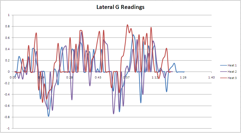
Figure 7. Lateral G readings over the three heat runs

Figure 8. RPM readings over the three heat runs
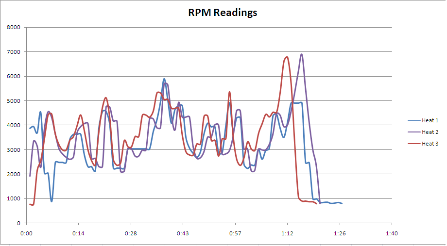
Figure 9. MPH readings over the three heat runs
Conclusion top
I was very satisfied by the end product. I managed to create a relatively useful device under specific constraints applying knowledge from ECE 4760 and Systems Engineering for product planning and development. Since I designed a PCB for the first time, it wasn’t the greatest one with some minor mistakes and for the future I would like to improve on that. I was able to learn a lot from various different projects such as – Avi’s and Mike’s OBD device and the Embedded Foot Pronation Detection by Wen Jie Zhou and Yilok Wong, whose SD card logging code I borrowed.
Ethical Considerations and a Societal Impact
The TrckrX project follows the IEEE Code of Ethics and during the development of the data logging device, no ethical concerns occurred or were brought up. This device poses no threat to the public and instead is designed to assist the public in enjoying their hobbies. All the electrical connection inside the TrckrX are properly isolated from any crucial parts of the vehicle or from the driver.
The device can be safely used at Autocross and Track day events without potential distraction to the driver. In addition, the device can be safely used on the road without provoking reckless driving.
Intellectual Property Considerations
There are multiple OBD devices providing similar capabilities but one with SD capabilities, lateral acceleration and on a budget doesn’t seem to be designed before. A laptop with an OBD to USB device can easily provide the user with a similar experience but the TrckrX is much more interesting, designed to fully blend with the interior of the vehicle and eliminates the need to carry a laptop everywhere.
Appendices top
A. Source Code and Schematics
Download the source code here.
Download the PCB layout here.
Download the overall schematics here.
B. Parts List
| Part | Description | Price | Availability |
|---|---|---|---|
| OBD-II ECUSim 2000* | Used for in lab testing | $200.00 | In Lab |
| microOBD 200* | OBD-II to UART communication | $80.00 | In Lab |
| ATmega644 | Core MCU | $6.00 | In Lab |
| Protoboard | Controlling the MCU | $12.00 | In Lab |
| Orange LCD Display | For displaying instantaneous data | $7.50 | Ordered |
| SD card | Data Storage | $0.00 | Previously owned |
| SD card slot | Interfacing the SD card | $0.00 | Previously owned |
| PCB Design and Fabrication | ExpressPCB | $44.60 | In Lab |
| 2 Axis Accelerometer | Measuring Lateral Acceleration | $3.00 | Ordered |
| ABS plastic | Used for front plate enclosure | $0.00 | Previously owned |
| Total | $73.50 |
*Cross-used between ECE 4760 and ECE 6131 with the permission of Pr. Bruce Land
References top
This section provides links to external reference websited and code used throughout the project.
Datasheets
References
Acknowledgements top
I would like to thank Pr. Bruce Land for giving me the opportunity to design something directly related to my hobby. This was one of the most enjoyable classes I have had in the past five years of my undergraduate and graduate education. I would like to also thank my friend Jason Lane for his ideas, for his car and unreserved help during the development of the TrckrX.