
Overview
For our ECE 4760 project, we developed a self learning 1 degree of freedom (DOF) helicopter using a neural network learning algorithm and infrared (IR) distance measurement. The primary goal is to increase the helicopter height to a desired level in the quickest amount of time and with the least amount of learning trials.
High Level Design top
Rationale
The purpose of our project is to learn how to wirelessly apply a neural net learning algorithm to an indoor helicopter. Iniitially, we intended on applying horizontal position control and vertical height control using phototransistors as distance measurement devices. However, the SYMA S107 Helicopter is sensitive to weighting due to IR LEDs . As a result, we constrained our experiment to a boom. All the user has to do is start the program and it will perform runs to maintain a particular height in the quickest amount of time possible. Readouts on the controllers fitness or performance can be provided through the UART interface and displayed on the Putty console.
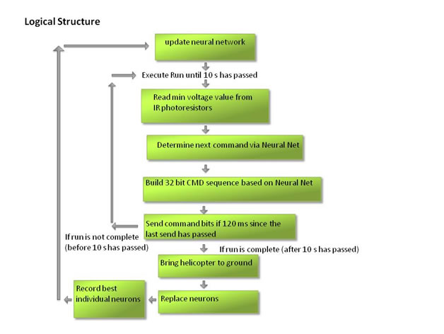
Logical Structure
The helicopter initially sits on a landing pad. At the start of the program, the microcontroller plans out a sequence of neural net commands to be performed over the period of 10 s corresponding to a neural net run. It then begins its first neural net run. It increases its height to a desired value in the quickest amount of time possible and hovers at that location. After 10 seconds the neural net run is over and the helicopter drops back down slowly. The microcontroller then adjusts the control parameters using the neural network and initiates the launch task again. The range of heights that we expect the helicopter to be able to reach are from 5 cm to 25 cm. Within each run, the program reads the voltages from the IR phototransistors, determines the next command to be sent to the helicopter, builds the command for the IR protocol and then sends the command via the the helicopters IR protocol. This process is repeated every 120 ms since the IR inter-packet period is 120 ms. When the run is over this cycle is stopped until the next sequence of neural net commands have been built.
Experimental Design
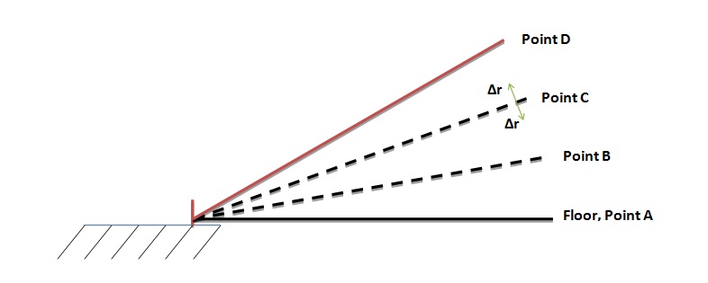
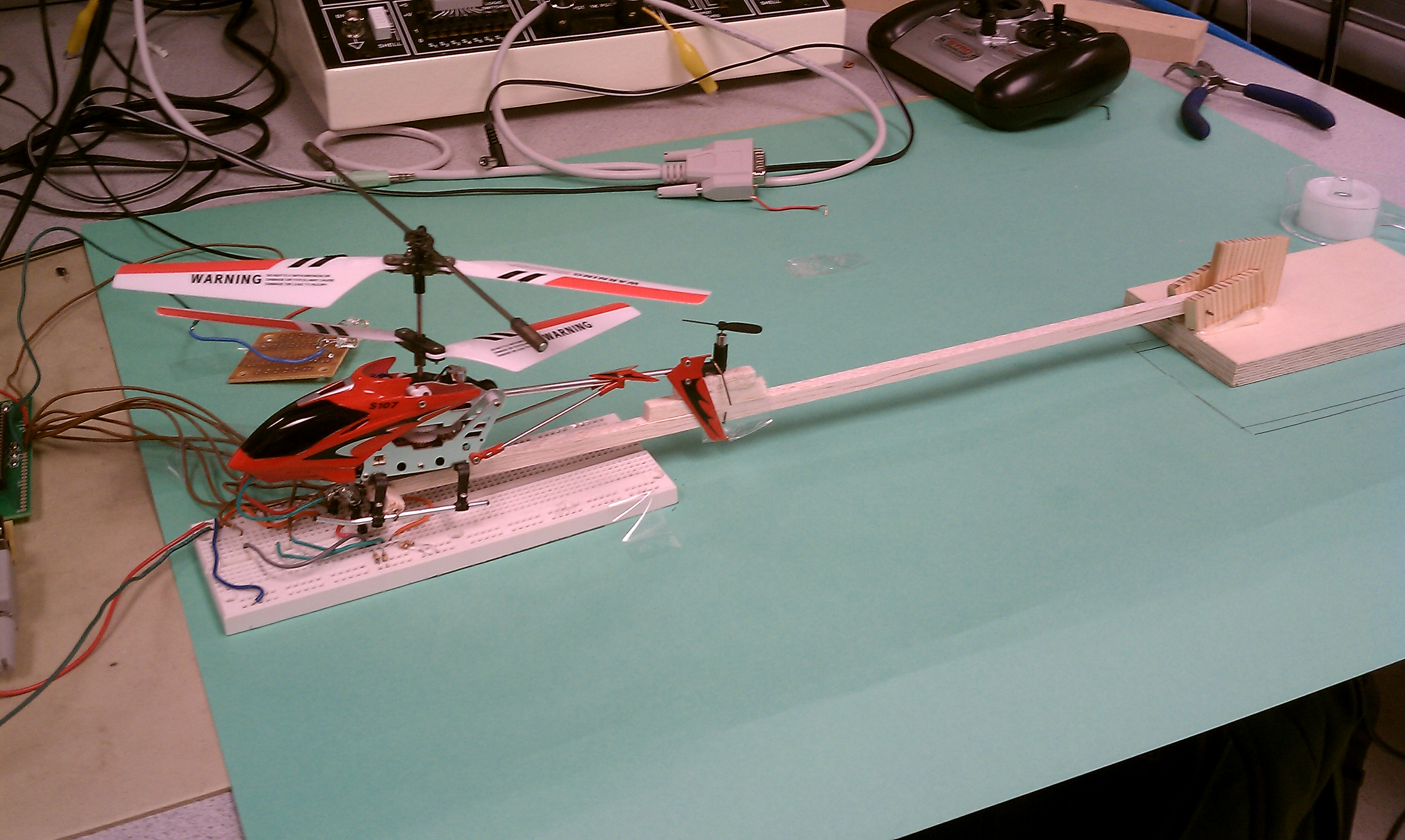
Figure 1: Experimental Setup
We trained the helicopter to reach a particular distance in the fastest possible time and also to hover at that distance. We implemented this training with a 10 second test and reference points as shown in Figure 1. The objective is for the helicopter to start at Point A, reach Point C, and hover there. Each test starts with a fitness of 0. The fitness is incremented or decremented throughout the 10 second test according to the following piecewise fitness function.
The highest fitness goes to those who hover at Point C ± Δr for the longest amount of time. The fitness increment is decreased proportional to the distance from Point C. If the helicopter reaches Point D, the run is terminated. At this height, it is likely that any further throttle will pull the helicopter back and break the boom. This fitness function inherently evolves the condition of fastest ascent to Point C because fast individuals will have more time at Point C and thus will accrue more fitness points.
We can choose the points as well as Δr by using the voltages read by the phototransistor network at each height. Adjusting the value of Δr will likely affect how good the hover is in a fully evolved network. For a very large Δr, the helicopter will have noticeable oscillations around Point C. For a very small Δr, the helicopter will appear to stay in a steady hover. However, smaller values of Δr will result in longer evolution times as the network needs to be better tuned. The following table shows the voltage values and the sensory inputs corresponding to each point. These were found through experimentation and trial and error.
Location |
Voltage (V) |
INPS |
A |
0.1 |
0xff |
B/2 |
0.2 |
0x7f |
B |
0.35 |
0x7f |
3B/2 |
1.0 |
0x3f |
C-2Δr |
2.0 |
0x1f |
C-Δr |
2.3 |
0x1f |
C |
2.8 |
0x0f |
C+Δr |
3.2 |
0x07 |
C+2Δr |
3.5 |
0x01 |
D |
3.7 |
0x00+end |
Table 1: Voltage Output of Phototransistor Circuit for Key Heights
Hardware Design top
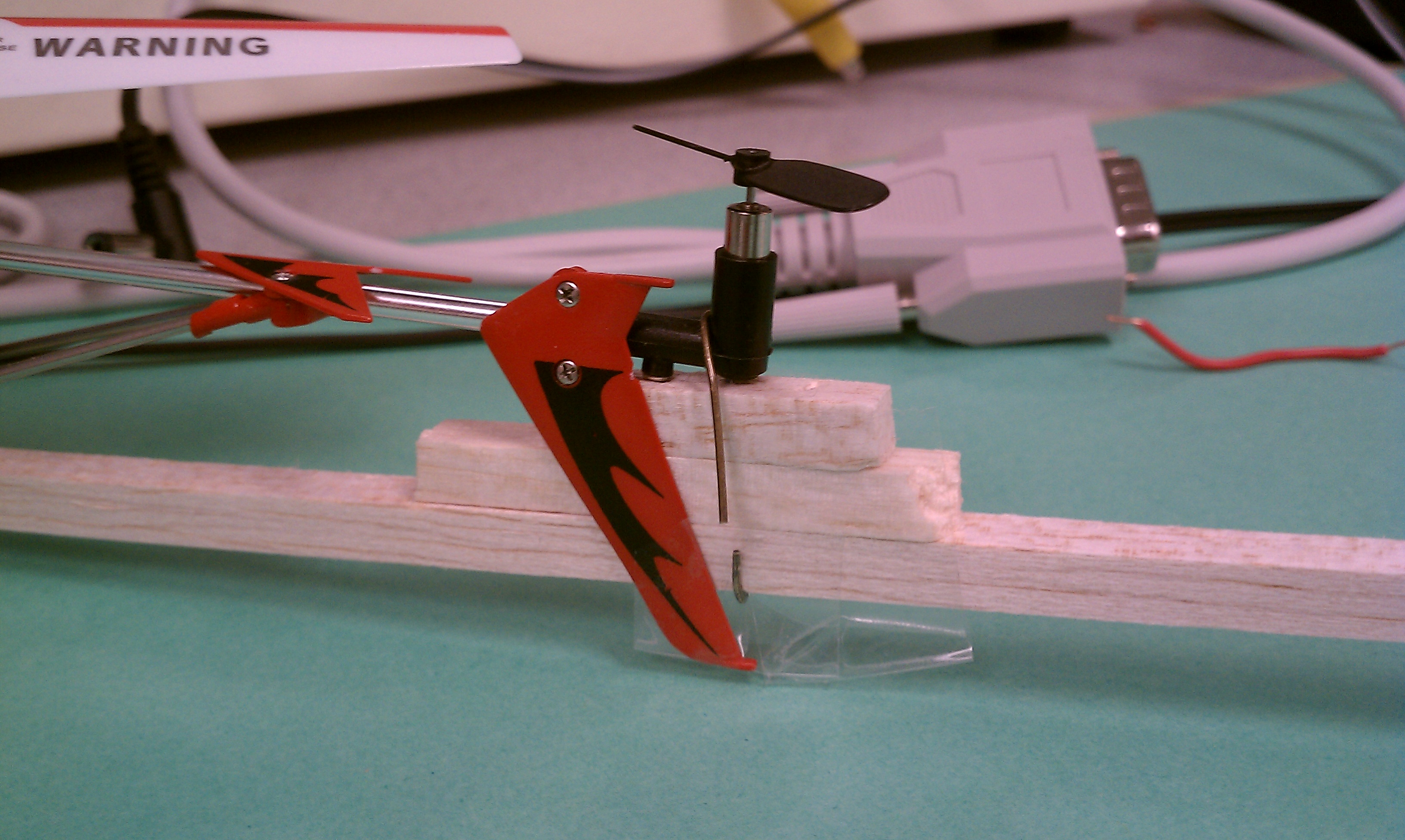
The vehicle used is a SYMA S107R5 Helicopter. The helicopter is constrained to 1 DOF via a wooden boom. To send commands to the helicopter we use an Atmega644 hooked up to an infrared emitter circuit. The helicopters multicolored LED was replaced with an IR LED to output a constant IR signal. This IR signal is received by an IR phototransistor circuit. The voltages at the output of the phototransistors correspond to the distance between the helicopters IR LED and the phototransistors. The microcontroller used is an Atmel Atmega 644. This is used with an RS232 module to output serial communication to the Putty Interface.
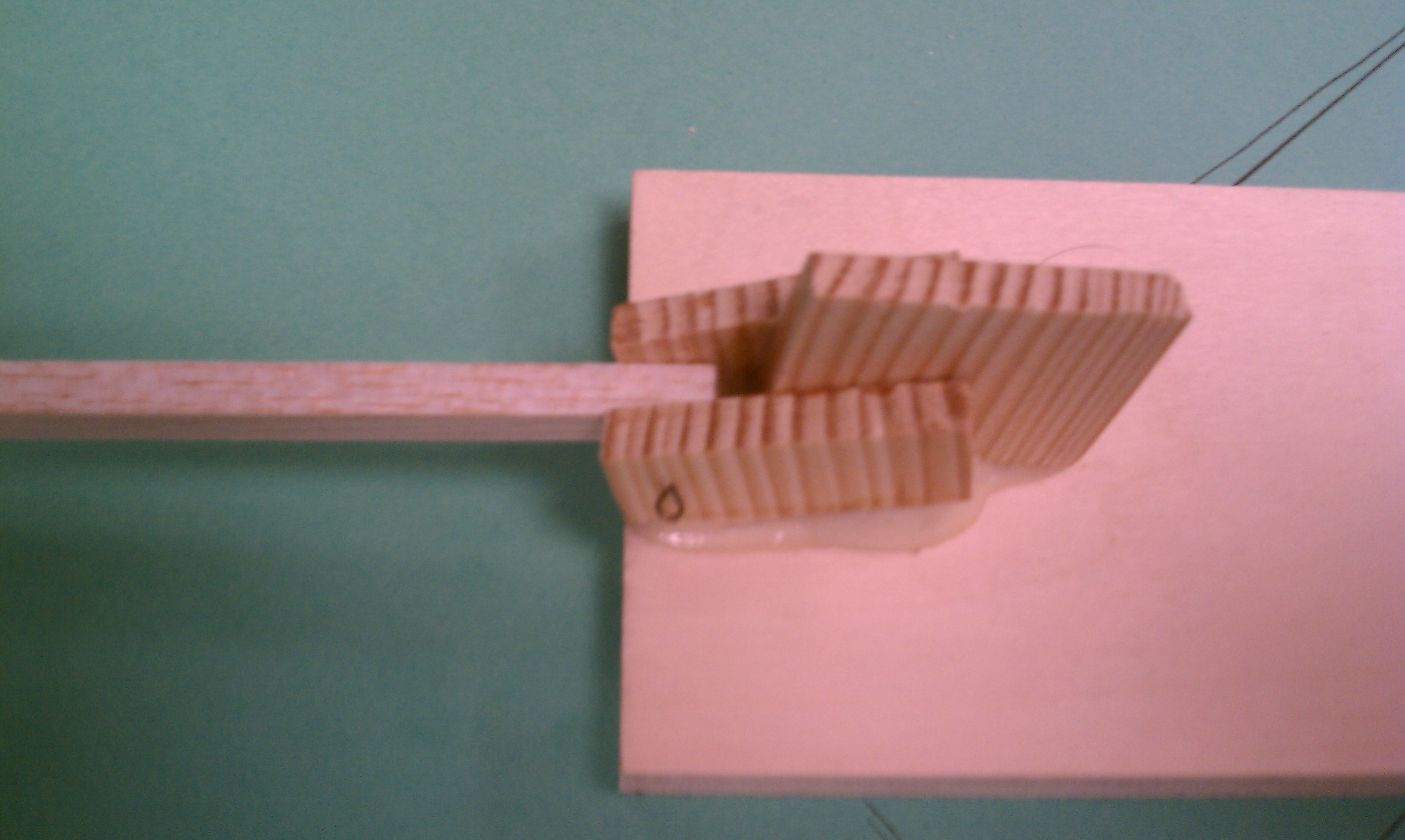
Boom
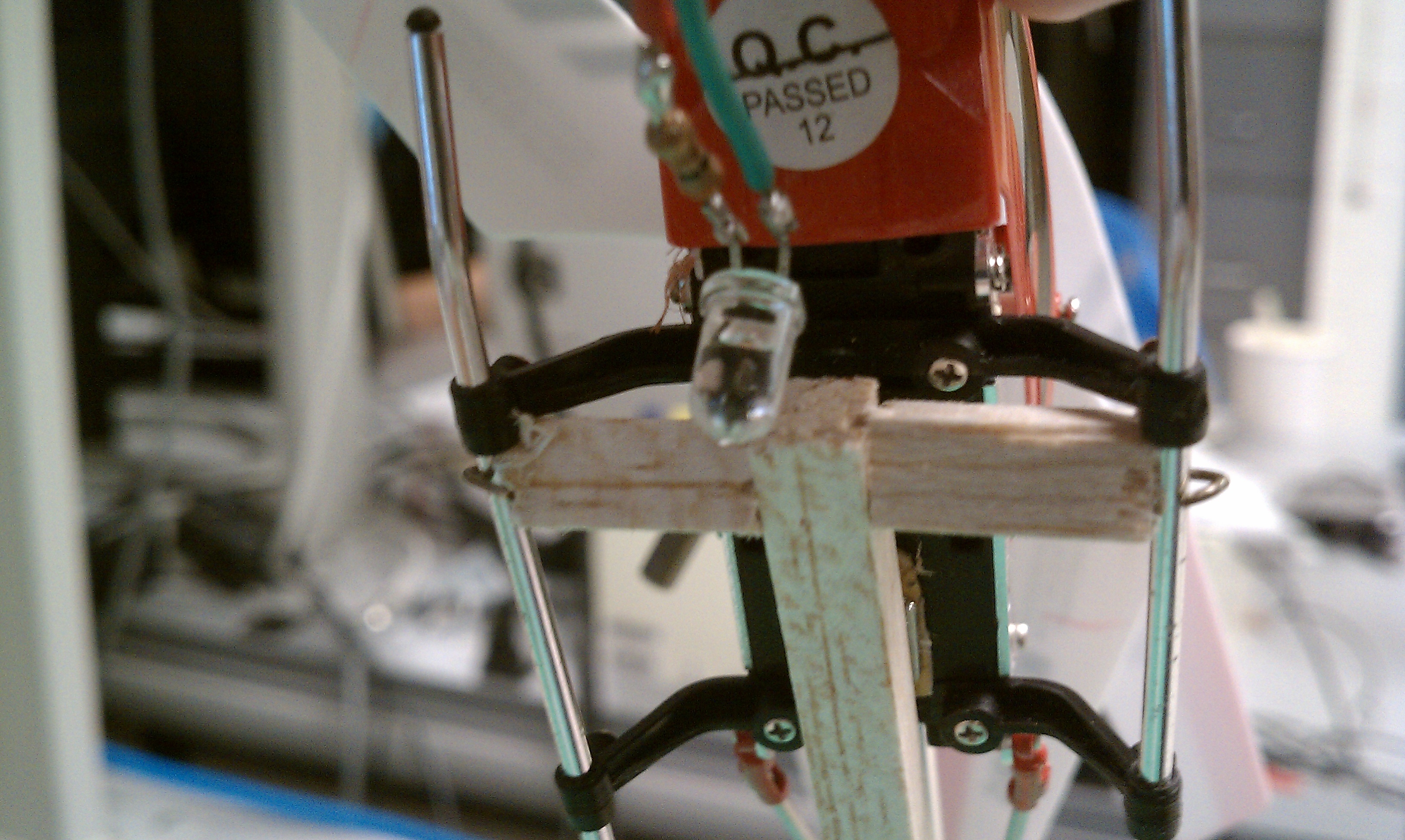
The boom was designed to reduce the system from 6 DOF to 1 DOF. The boom was easy enough to build. We made a hinge at the bottom by using two pieces of wood with a pin going through the center. The lever was a 12 inch balsa wood dowel was attached to the hinge. The other end was attached to the front supports of the helicopter using balsa wood spacers and another pin. The tail was constrained to prevent the pitch DOF by attaching the tail to the lever using balsa wood spacers and tape.
Helicopter Modification
The purpose of the IR Led on the helicopter is to output a continuous IR signal to be used by the phototransistor circuit to determine the distance from the helicopter to the ground. To hook up the IR LED we removed the multicolored LED from the helicopter to reduce power draw, and wired up the IR LED directly to the helicopters power supply in series with a 330 Ω resistor. The output voltage of the helicopters battery is 4.2 Volts which when using a 330 Ω resistor, provides about 12.7 mA of current to the IR Led. Originally, we used a 100 Ω resistor, since it would result in about 42 mA flowing through the IR led and we would therefore increase the range. However, we found that when we did so the helicopter would not respond to commands. This indicated that the current draw was too large for the helicopter to handle, leading us to increase the resistance. Via testing we found that with the LTE4208 IR LED and 12.7 mA, we obtained a maximum readable distance of about 25 cm and a minimum of about 2 cm.
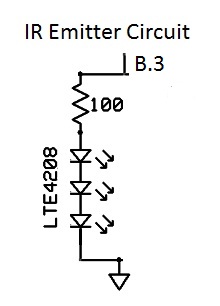
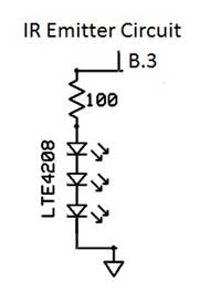
IR Emitter Command Circuit
The purpose of this circuit is to send IR commands to the helicopter for actuation. The IR emitter circuit consists of a 100 Ω resistor, and three LTE4208 IR LEDs. To send commands, the B.3 pin on the MCU is switched high or low. The output voltage of the MCU pin is about 5 V when switched high. With a 100 Ω resistor, the output current through the LEDs is about 50 mA. The max current of these LEDs is around 50 mA. Three IR LEDs were used at the maximum current to make sure that the helicopter receives its IR commands appropriately via its onboard IR receiver. We found that with only 1 IR LED the range at which commands can be sent and the reliability of the command signal is decreased.
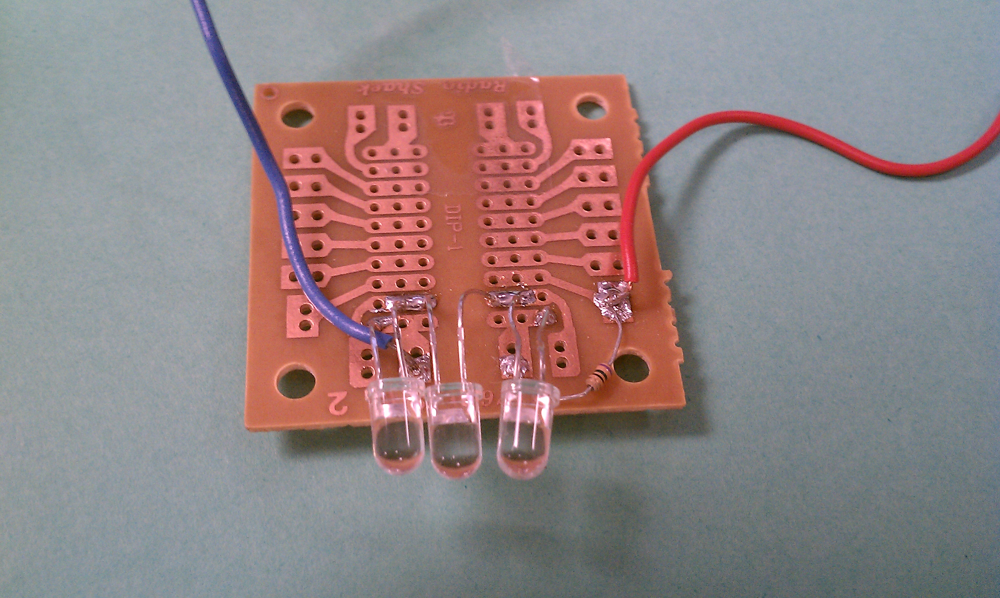
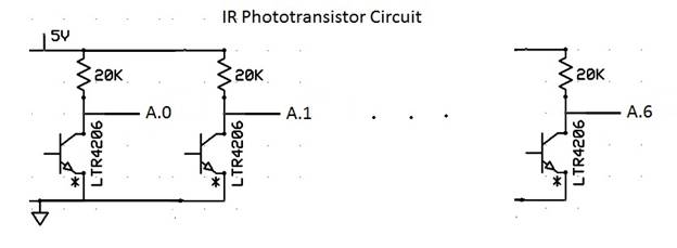
IR Phototransistor Receiver Circuit
The purpose of this circuit is to determine how far the helicopter’s IR LED is from the photoransistor circuit and thereby the distance from the helicopter to the ground. The circuit consists of 8 identitical branches in parallel between the MCU’s power and ground. Within each branch, there is a 20kΩ resistor and a LTR4206 IR phototransitor. These output a voltage at the collector corresponding to the intensity of the receiving IR signal where 5 Volts corresponds to no intensity and 0 Volts corresponds to the maximum intensity it can detect. The voltages at the collector of the phototransistor are fed to the Analog to Digital Converter input pins on the MCU (A.0-A.6).
Software Design top
Overview
The software was organized in a series of runs. Each run is a 10 second test as described in the experiment setup section. These runs use an evolutionary algorithm adopted from Floreano et al. The algorithm uses a spiking neural network and performs random walks to determine the connections of the network. The output of this network is used to determine the throttle of the helicopter. Better individuals undergo further mutations until the network converges on solutions that maximize the fitness function. The flight parameters are transmitted every 120ms to the helicopter using a fast PWM to send infrared LED pulses. The best runs are recorded in eeprom periodically.
Initialization
Port B.3 is designated as the output to the IR command module. Two timers are setup to operate at different time steps. Timer 0 is set up to operate at a 13 µs tick and timer 2 is set to operate at a 1 ms tick. The reason we used two separates timers to time was that timer 0 was used only to send IR pulses to the helicopter and timer 2 was used as more of a high level timer for the code. 1 timer could have been used, but we decided to implement it with 2. The USART is setup for data logging. The A-D converter is set up for a left adjusted output as in Lab 2.
The previous initializations are the usual and were used in previous labs. However, new initializations had to be set up for the evolutionary algorithm. First, the random number generator is seeded. Then, all of the deterministic parts of the network are initialized such as thresholds and membrane potentials. Finally, the signs as well as sensory and motor connections are randomly generated for 6 individuals.
Evolutionary Algorithm
1. Background
Evolutionary algorithms (EA) are random searches that mimic the process of natural selection. EA performs random walks in multidimensional feature spaces in order to find solutions to optimization problems. A solution is called a chromosome, and it is evaluated according to a fitness function. It has a high fitness if it optimizes the problem well according to user specifications. It has a low fitness if it does not. Multiple chromosomes are instantiated at the beginning of the search. Those with high fitness reproduce and mutate in a random fashion in order to form new chromosomes. Those with low fitness are discarded. Each iteration of this algorithm on all chromosomes results in a new generation of chromosomes. The EA iterates for multiple generations until the search converges on a solution and the fitness values across generations barely increase.
EA can be implemented in many ways; this project uses an implementation presented by Floreano et al. A neural network is used to mimic the sensory/motor nature of our task. We want the system to use a certain sensory input and map it to a motor output in the helicopter. The sensory input is the distance of the helicopter from the floor, and the motor output is the throttle of the helicopter. In neuroscience, such a system is able to be configured to optimize a certain task. I will briefly describe the biology behind the idea. Sensory input and motor output are each manifested as neurons, which have associated membrane potentials. These neurons send “spikes” or extremely fast voltage swings when the membrane potential passes a threshold. Neurons can send these spikes through a connection that terminates or synapses onto other neurons (i.e. the terminal neurons). The terminal neurons’ membrane potentials are affected by presynaptic neurons (i.e. those that synapse onto the terminal neuron). The terminal neuron’s membrane potential can increase if the presynaptic neuron is excitatory or decrease if the presynaptic neuron is inhibitory. As such, presynaptic neurons can spike enough to cause terminal neurons to spike. The connections between presynaptic and terminal neurons can be configured in order to allow the motor output to react to sensory input in a desired manner. This is the basic principle behind learning motor activity in biological systems.
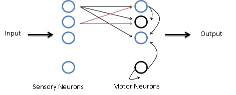
Figure 2: Example Neural Network. Connections are shown by thin arrows
Our basic artificial neural network has sensory neurons acting as the presynaptic neurons and motor neurons acting as the terminal neurons. A more complicated network allows the motor neurons to also synapse onto each other. The variables in this network are the connections between sensory and motor neurons, the connections between motor and other motor neurons, and whether each neuron is excitatory or inhibitory. Sensory neurons spike based on the level of sensory activity, and they are considered to be excitatory in simple models. Motor neurons spike when their membrane potential crosses a threshold. They can be excitatory or inhibitory. This basic network is shown in Figure 2. The blue circles are excitatory neurons and the black circles are inhibitory neurons. Sensory neurons synapse onto motor neurons, and motor neurons can synapse onto each other. The red arrows are shown just to distinguish those connections from overlapping ones. Several chromosomes that represent the aforementioned variables are instantiated and evolved until the system converges on a high fitness solution. This algorithm applies the EA to a neural network in order to “teach” the helicopter altitude control.
2. Digital Implementation
A simple neuron can be modeled by only 5 attributes. The 0th attribute is that at any time, a neuron is either spiking or not spiking. A 1 signifies a spike and 0 signifies no spike. The 1st attribute is that a neuron cannot spike for a cycle after it has spiked. This is called a refractory period. The 2nd attribute is that all incoming neurons can input to a certain neuron. All these inputs have contributions depending on whether they are spiking or not. These contributions sum and change the membrane potential of the particular neuron (the 3rd attribute). For example, if a neuron has 3 excitatory inputs and only 2 are spiking, then the membrane potential of the neuron increases by 2. The 4th attribute is that the neuron will spike if its membrane potential has risen above a threshold. We model the threshold as 5 + a random number between -2 and 2. The addition of the random number ensures that the system does not result in locked oscillations. The 5th attribute is that some amount of leakage will always decrement the membrane potential. We used a value of 1 for the leakage. All these attributes represent a single neuron.
Our implementation uses 8 sensory neurons and 8 motor neurons. The sensory input is voltage readings from the phototransistors that give us a sense of the distance of the helicopter from the floor. These readings are read from the analog to digital converter. The 8 bit output of the A-D corresponds to the 8 sensory neurons. 1 bit per neuron represents whether that neuron is spiking or not. When the helicopter is very close to the ground, we make all sensory neurons spike in order to generate a high amount of motor output. We take motor output from 3 motor neurons. The first 2 increase the throttle and last decreases the throttle. The other 5 neurons are just for intermediate connections. High motor output near the ground will cause the helicopter to increase throttle rapidly and elevate to the desired height. Near the desired height, fewer sensory neurons are set to spike as the desired motor output is to slow down. The exact values of the sensory inputs corresponding to certain heights are described in the experimental set up section.
When a sensory input is taken, the network is updated using the current configuration of connections and signs. Each motor neuron is updated according to the attributes described above. If a neuron spiked the last time the network was updated, then that neuron cannot spike. If a neuron did not spike the last time, its membrane potential is updated according to the number of inputs and their signs. This can be done easily using the following statement:
MEMB[i] = sum(INPS & ICONN[i]) + sum(OUTPS & SIGN & NCONN[i]) - sum(OUTPS & (~SIGN) & NCONN[i]);
INPS is a byte that represents the sensory neuron spikes. ICONN is a byte that represents the connections of the ith motor neuron to the sensory neurons. NCONN is a byte that represents the connections of the ith motor neuron to the motor neurons. 1 signifies a connection and 0 signifies no connection. OUTPS is a byte that represents the motor output spikes. SIGN is a byte that represents the sign of the motor neurons. 1 signifies excitatory and 0 signifies inhibitory. Sum() is a macro that returns the number of 1s in a byte. So the above statement updates the membrane potential through input connections and excitatory motor connections. It also decrements the potential through inhibitory input connections. If the neuron’s potential is above 5 plus a random amount between -2 and 2, then it spikes. Otherwise, it retains a value of 0. Finally, a leakage constant of 1 is subtracted from the membrane potential. The network update occurs several times for each set of sensory inputs. This is done so that the number of output spikes can be counted and scaled to set the throttle of the helicopter.
Each network can be described using only 17 bytes. The first byte, SIGN, signifies the excitatory or inhibitory nature of the output neurons. The next 8 bytes, NCONN, are the connections of each motor neuron to the sensory neurons (1 byte per neuron). The next 8 bytes, ICONN, are the connections of each motor neuron to the motor neurons. Therefore, a chromosome can just be an array of 17 8 bit integers. This is shown in an example in Figure 3. The concept for this figure is adopted from Floreano et al. The vertical neurons on the left are the motor neurons. The horizontal neurons on the top left are motor neurons. The horizontal neurons on the top right are sensory neurons. Connections between neurons are shown by 1 (connection) or 0 (no connection). The SIGN is shown by the color of the neuron (black for inhibitory and blue for excitatory). This figure can be used to completely describe a chromosome.
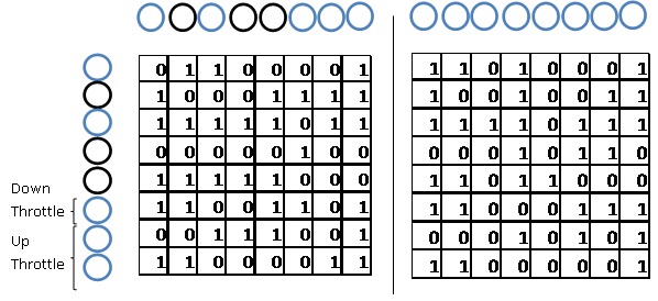
Figure 3: Example of a chromosome for the neural network. Shows connections between neurons as well as signs.
Initially, 6 chromosomes are initialized using the random number generator. The pool of chromosomes is called a population. The program is organized in runs. That means that a random chromosome in the population is chosen. That chromosome undergoes mutation. A random bit in the SIGN byte is toggled. A random bit in a random byte of the NCONN block is toggled. The same happens for the ICONN block. This ends the process of mutation. This chromosome is now ready to be tested. The timer starts counting, and network starts to update and produce motor outputs. Every 120 ms, this iterates. Sensory inputs are taken, the network is updated, and motor outputs are produced and converted to throttle. The fitness is incremented as the sensory inputs are taken according to the function described in the experiment set up section. The run is terminated after 10 seconds or after the helicopter steers off course. The fitness of the run is then compared to the fitness of every chromosome in the population. If the fitness is better than the worst chromosome in the population, then the recently tested chromosome is written over the worst one. Otherwise, the recently tested chromosome is discarded. Finally, the best individual is written to the UART terminal. The system waits for 1 second and mutates another chromosome to be tested.
Mutations and runs are performed until the user is satisfied with the altitude control. Every 10 runs, the population is written to eeprom. This is useful because it allows the user to charge the helicopter and return to the same conditions.
Random Number Generator
The 32 bit linear feedback shift register from Lab 3 was used as a random number generator. 8 shifts were performed on one call to this method, resulting in an uncorrelated, random number on every call. Since this random number generator is only called at well under 10 kHz, the system will not reproduce random numbers for the amount of experimentation time (~30 minutes). The EA demands high quality, uncorrelated random numbers in order to efficiently search the solution landscape. This random number generator meets those requirements. Refer to the Lab 3 writeup for more information on this generator.
IR Protocol
The SYMA S107R5 receives commands from a controller using a particular IR protocol. The message consist of roughly 30 ms packets sent with a period of 120 ms from each other. Each packet contains a header bit, 32 command bits and an ending bit. All of these bits are sent over a carrier wave with a frequency of 76.923 kHz. To obtain a basic verification of the IR protocol we outputted a signal via a controller or our command circuit, stopped the oscilloscope when the sample size was 25 ms/div to verify packet timing and 10 ms/div to verify bit timing and sequencing, and saved the plots to a flash drive.

Figure 4: Two IR Protocol Packets spaced 120 ms apart
Each packet contains a header, 32 command bits and stop bit. The header bit is a pulse on and off, each with a value of 2 ms. The 32 command bit sequence consists of 4 bytes. Each byte corresponds to an actuation command. The first byte represents yaw, the second byte is pitch, the third byte is thrust and the 4th byte is yaw correction. The first bit of each of these bytes is set to 0. The other 7 bits corresponds to an int value for the parameter in question. The 17th bit is called the command bit. This is used to set the controller between A and B mode along with packet timing. In mode A, the period of the packets is 120 ms with the control bit set to 0. In mode B, the period of the packets is 180 ms.
If we represent Y as yaw, P as pitch, C as the control bit, T as thrust, y as yaw correction and ![]() as the stop bit, the command sequence looks like;
as the stop bit, the command sequence looks like;
![]()
Since only 7 bits are allocated, each parameter ranges from 0 to 127. For thrust, 0 corresponds to no thrust and 127 to max thrust. For yaw, pitch and yaw correction, 63 corresponds to no yaw, pitch or yaw correction. For yaw and yaw correction, 0 corresponds to full yaw to the right and 127 corresponds to full yaw to the left. For pitch, 0 corresponds to full pitch up (full speed back) and 127 corresponds to full pitch down (full speed forward). For instance, the following command sends no yaw, pitch or yaw correction with full throttle. The ![]() bit at the end is simply a pulse on for
bit at the end is simply a pulse on for ![]() pulse and off for the amount of time between the end and start of a packet, which is around
pulse and off for the amount of time between the end and start of a packet, which is around ![]() for mode A.
for mode A.
![]()
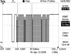
Figure 5: 1 IR Protocol Packet. Packet shows 1 header, 32 command bits and 1 stop half bit. Cmd = [H 00111110 00111111 01111111 001110110 *]
To represent a 0, the IR emitter is pulsed on for ![]() and off for
and off for ![]() . To represent a 1, the IR emitter is pulsed on for
. To represent a 1, the IR emitter is pulsed on for ![]() and off for
and off for ![]() . The carrier wave was the trickiest part. When the IR emitter is turned on for the low portion of a header or bit, the emitter needs to be flashed on and off every
. The carrier wave was the trickiest part. When the IR emitter is turned on for the low portion of a header or bit, the emitter needs to be flashed on and off every ![]() . The oscilloscope image above does not show the carrier wave because the IR phototransistor we were using, LTR4206 has a fall time of
. The oscilloscope image above does not show the carrier wave because the IR phototransistor we were using, LTR4206 has a fall time of ![]() and therefore can’t show changes on the order of
and therefore can’t show changes on the order of ![]() . If it could show higher frequencies, then we would see that the low portions of the header and bits consist of a 76.973 kHz wave form ranging from 0 to 5 volts.
. If it could show higher frequencies, then we would see that the low portions of the header and bits consist of a 76.973 kHz wave form ranging from 0 to 5 volts.
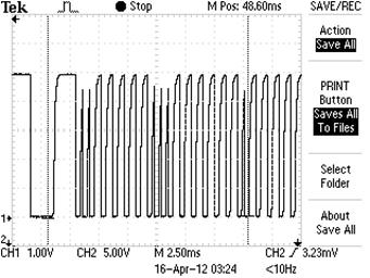
Figure 6: Close up of the IR Protocol bits.
Results top
The following graph displays the best fitness sampled every run, which lasts 10 seconds. The function displays rapid increases in the fitness in the beginning as the system randomly discovers good chromosomes. It becomes harder to discover better chromosomes as the system evolves. The system initially uses plenty of configurations that go too high and cause the program to stop a run. It quickly learns to avoid these chromosomes as they result in 0 fitness. The system also learns to avoid chromosomes that barely move the helicopter up because these chromosomes also result in very low fitness values.
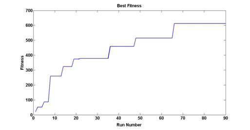
Figure 7: Best fitness in population sampled at every run
The following graph shows the average fitness of the entire population sampled every 5 runs. Again, a high slope is exhibited in the beginning. The population takes longer to get better after the initial 40-50 runs (shown in the graph as 8-10).
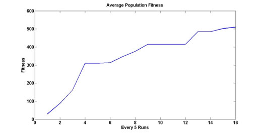
Figure 8: Average fitness of entire population sampled every 5 runs
The following chromosome achieved the highest fitness of 612.
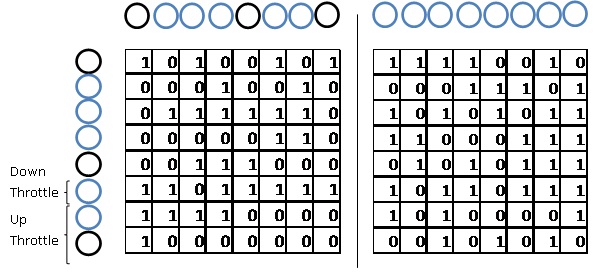
Figure 9: Network connections and sign for best chromosome>
The phototransistor network is adequate at measuring the distance of the helicopter. Because the LTR 4206 phototransistors only have a 20⁰ viewing angle, the helicopter must be positioned directly above them. Frequently, the helicopter rotates or shifts a very small amount at higher altitudes. This causes the IR LED to go out of the viewing angle area. The system interprets this as a bad run, which results in a false negative for a chromosome that might have had a high fitness. The system also generates several false positives for chromosomes that rise to low altitudes but evade the viewing angle of the phototransistors just enough to trick the sensors into thinking that the helicopter is at the right altitude. These chromosomes generate high fitness values for bad runs and severely hamper the evolutionary capability of the network. However, enough mutations and runs ensure that false negatives and false positives do not hamper the end goal of the system.
There was no interference from other IR sources since the viewing angle and range of our phototransistors was so small.
Conclusions top
Issues and Workarounds
A key issue with the EA was how to slow the helicopter as it reached its target point. The problem with our mechanical set up was that the helicopter needed less throttle to elevate as it reached higher altitudes. On the floor, the helicopter needed a throttle value of 60 to get up. At target range, a throttle value of 60 would send the helicopter way up and break the boom. Therefore, we had to subtract a large amount from the throttle when the helicopter reached the target range. Though this resulted In worse oscillations around the target range, it prevented the helicopter from breaking the boom and it resulted in a faster search for better chromosomes. Otherwise, most chromosomes were passing the target range and getting fitness values of 0.
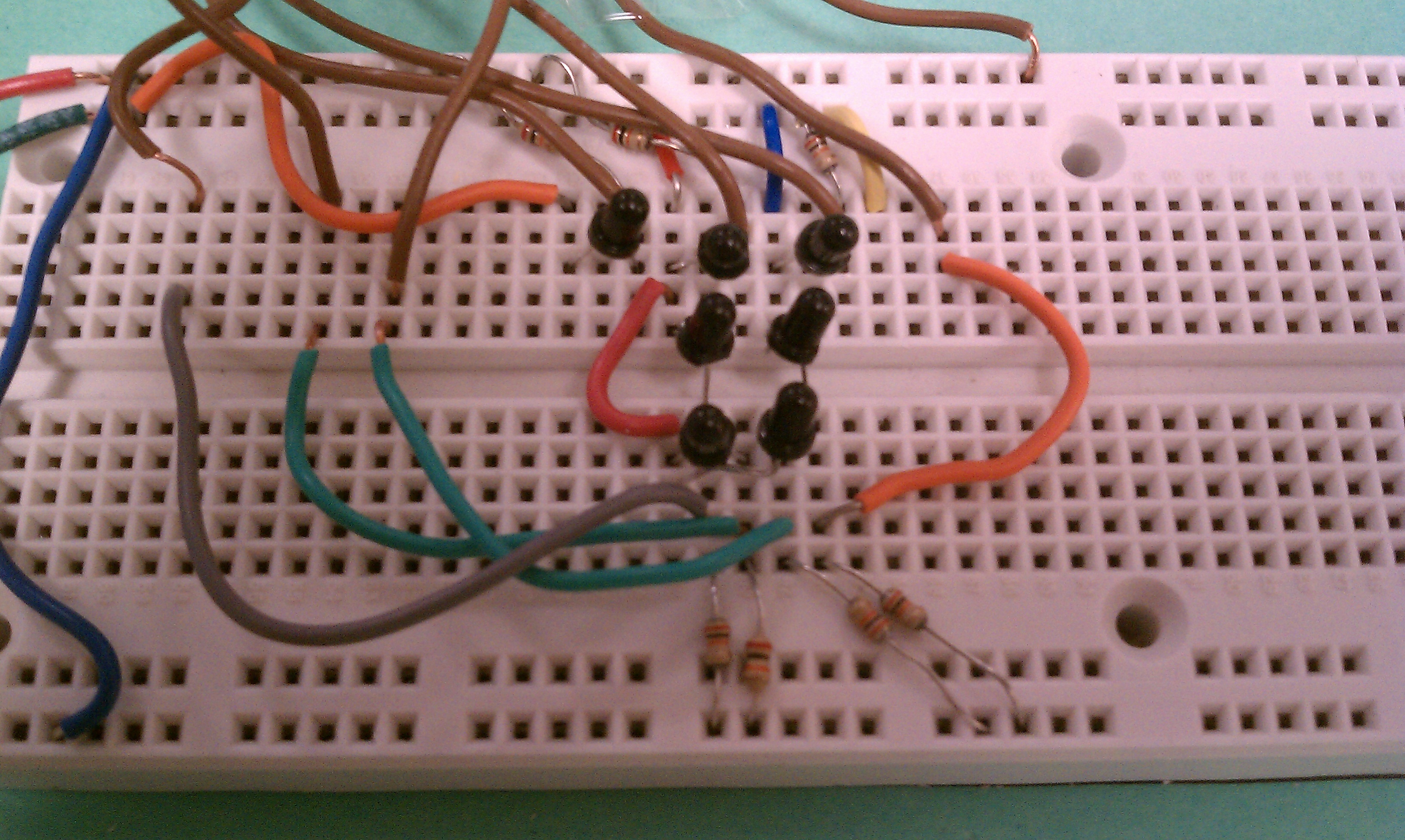
As discussed in the Results section, the EA was prone to false positives and false negatives due to the variability in distance measurement. We tried to stabilize our boom as much as possible, but even the smallest variability at higher altitudes would affect the voltage reading by as much as 2 V. This could result in the end of a good run (a false negative) or the continuation of a bad run (a false positive). We experimented with several configurations of phototransistors in order to minimize the effects of this problem. In order to make reconfiguration easy, we implemented the network on a whiteboard instead of soldering it. We tried a straight line of 8 phototransistors, 4 rows of 2, 2 columns of 4, and even two concentric circles. In the end, we settled on the design shown in the hardware design section.
We found that this design made it difficult for the system to take improper readings. We also had to reposition the boom to ensure that the IR LED was always in the viewing angle range of the phototransistors. A quick fix for this problem was to change the floor position of the helicopter to be slightly in front of the network. This is shown below.
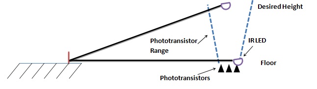
Figure 10: Depiction of Phototransistor Range
The helicopter is not shown for simplicity. The IR LED (purple) is at the end of the boom (black line). At both floor and desired height positions, the phototransistor range is in the path of the IR LED. This makes it more difficult for the helicopter to get out of position and for the network to produce false readings.
One interesting problem we ran into was trying to debug the flow of the program. We wanted to print to the UART terminal when the program was choosing a throttle, building a command, and sending it to the helicopter. However, the process of printing takes a significant amount of time. This time was enough to cause the IR pulses to be delayed, resulting in different lengths for high and low pulses. The helicopter could not register this and did not move. We only realized the issue when we hooked the oscilloscope to our command module and saw that the packets took much longer than 30ms to transmit.
A big issue was the low battery life of the commercial helicopter we used. After 5 runs, the battery life had depleted to the point where the same run cannot lift the helicopter as high. To circumvent this issue, we had to stop the code after 5 runs, save to eeprom, and charge the helicopter. The charging process took 10-15 minutes each time, which greatly hampered our ability to rapidly test and debug. When we were finished recharging, we restarted the program, which read the previous chromosomes from eeprom. We also tried to run remove the battery and run the helicopter from an external power source of 4.2 V. However, with this setup, the helicopter would not consistently respond to commands. Most of the time, it performed no actuation.
Originally we wanted to apply this concept to a helicopter in 6 DOF space, using the phototransistors to obtain three dimensional position information. When we first took the helicopter out of the box, the helicopter was stable with respect to sagital and lateral motion. However, after adding an infrared led, the helicopter’s weight was thrown off, leading to lateral “strafing” motion. This would have been almost impossible to control for considering we can only apply yaw and pitch horizontal control. As a result, we constrained the helicopter to the boom and applied a 1 DOF neural net controller to manage the height of the helicopter. A future solution would be to use much smaller wires to attach the IR led.
Future Work
f we could do this project over there would be a couple of things we would change. The helicopter was a limiting factor in our project. It's small size and weight leaves it prone to weighting and indoor air flow sensitivity. This would have prevented the strafing motion which would have made it easier to perform this experiment in 6 DOF space. If we were to choose this helicopter again we would try to use smaller diameter wires to attach the infrared LED on the helicopter to the battery. A tethering scheme would be attempted to try to run this project in 6 DOF. If we were to use the boom, we would have spent more time investigating the tethering of the power supply to the helicopter. For the phototransistor circuit, we would have used phototransistors with larger viewing angles to improve the reliability of distance measurements. We would have also physically constrained the helicopter and circuit such that the helicopter's LED stops a centimeter above the phototransistor circuit.
IP Considerations
We adapted the EA from Floreano et al. Past projects in ECE 4760 have also used the algorithm. Since these projects asked Dr. Floreano and his work is in the public domain, we felt it sufficient to cite his paper.
The infrared protocol was reverse engineered for the SYMA S107. Since we are not intending on patenting or publishing any part of this project, there are no conflicts with IP concerning this.
Ethical Considerations
In accordance with point 3 of the IEEE code of ethics, we did our best to report the results of the EA. However, it is inherently a random algorithm, so results will not be exactly reproducible. Nevertheless, the algorithm should be able to evolve good chromosomes given enough time. The infrared LED's were chosen to be low intensity for health considerations. We made sure that the helicopter was securely fastened to our boom structure in order to prevent the helicopter from flying back and causing possible injury in the public lab area.
We have improved our technical competence in the subject of microcontrollers and general implementation of electronics. We have cited and referenced the work of others in the development of our ideas and implementations. We received and acknowledged help from our instructor, Bruce Land, and several peers. In the presentation of this work on this webpage and related videos, we understand that the risk and potential negative consequences of this work are minimal. Our work is merely meant to demonstrate the training of a toy helicopter in a lab setting.
There were no percieved conflicts of interest, personnel issues, or discriminations involved in the development of this project. No cash reward was involved in any way.
Legal Considerations
The main legal issue with our design would be the use of an infrared beam through an LED. According to the IEC, infrared emitters or lasers with a wavelength of 940 nm are classified as Class 1M lasers. These types of lasers are safe as long as optical aids such binoculars are not used in series with the laser. Our setup does not use optical aids. No other standards or restrictions were found.
Appendix top
Schematics
Links to Data Sheets
- LTE4208 LED Emitter - http://rocky.digikey.com/WebLib/Lite-on/Web%20Data/E4208.pdf
- LTR4206E LED phototransistor - http://rocky.digikey.com/WebLib/Lite-on/Web%20Data/LTR-4206E.pdf
Cost Details
|
Specific Tasks
- Structure of code – Sergio
- Neural net design and programming – Akshay
- Boom construction – Sergio
- IR protocol – Sergio
- Phototransistor circuit design and construction – Akshay
- Emitter circuit design and construction - Sergio
- Website programming - Sergio
Data Sheets/Background Papers/Websites Referenced
References
- Floreano, Dario, Nicolas Schoeni, Gilles Caprari, and Jesper Blynel. “ Evolutionary Bits’n’Spikes.” International Society of Artificial Life 8 (2002): 335-44
- Slovak, Rebecca, Matt Meister, and Elias Bermudez. Learning Helicopter, ECE 476 Spring 2008 Final Project. Rep. Cornell University, 2008. Web. 01 May 2012. <http://people.ece.cornell.edu/land/courses/ece4760/FinalProjects/s2008/ras94_mrm58_deb48/ras94_mrm58_deb48/HelicopterWebsite.html>.
- Drew, David, and Joanna Dai. Autonomous Directional Rotary Artificial Intelligence Navigational System (ADRAINS). Rep. ECE 4760 Cornell University, 2007. Web. 01 May 2012. <http://people.ece.cornell.edu/land/courses/ece4760/FinalProjects/s2007/jxd2/djd36_jxd2/neuralrobot.htm>.
Relevant Previous Projects from ECE 4760
- Automated Paddle-Controlled Helicopter - http://people.ece.cornell.edu/land/courses/ece4760/FinalProjects/s2011/gmb67_jdw229/site/index.html
- Neural Net Learning Helicopter - http://people.ece.cornell.edu/land/courses/ece4760/FinalProjects/s2008/ras94_mrm58_deb48/ras94_mrm58_deb48/HelicopterWebsite.html
Online References
- IR Protocol for Syma S107 - http://www.avergottini.com/2011/05/arduino-helicopter-infrared-controller.html
- RC groups blog - http://www.rcgroups.com/forums/showthread.php?t=1417249&page=3
Commented Code
// ECE 4760 Final Project
//Sergio Biagioni and Akshay Dhawan
#include <inttypes.h>
#include <avr/io.h>
#include <avr/interrupt.h>
#include <avr/pgmspace.h>
#include <stdio.h>
#include "uart.h"
#include "uart.c"
#include <util/delay.h>
#include <string.h>
#include <avr/eeprom.h>
#define bit30 0x4000
#define bit27 0x0800
#define begin {
#define end }
#define bit7(x) (x & 0x04)>0
#define bit8(x) (x & 0x08)>0
#define VMAX 5
#define sum(x) ((int)((x) & 0x01) + (int)(((x)>>1) & 0x01) + (int)(((x)>>2) & 0x01) + (int)(((x)>>3) & 0x01) + (int)(((x)>>4) & 0x01) + (int)(((x)>>5) & 0x01) + (int)(((x)>>6) & 0x01) + (int)(((x)>>7) & 0x01))
#define MAX_THROTTLE 127
#define begin {
#define end }
// set up serial for debugging
FILE uart_str = FDEV_SETUP_STREAM(uart_putchar, uart_getchar, _FDEV_SETUP_RW);
// parameter initialization
unsigned char state;
unsigned char substate;
unsigned char sendFlag;
unsigned char pulseFlag;
unsigned char printFlag;
unsigned char bitn;
unsigned char bitpart;
unsigned int time1;
unsigned int time2;
unsigned int time3; // 16 bit int overflows every 0.8520 seconds, use long instead
uint8_t min_location;
float voltage;
unsigned char cmd[32] = {0,0,1,1,1,1,0,1, 0,0,1,1,1,1,1,1, 0,1,0,0,0,1,1,0, 0,0,1,1,0,1,0,1};
unsigned char subcmd[8];
unsigned char subcmd_type;
unsigned int subcmd_int;
unsigned char ii;
unsigned char jj;
unsigned int osc_i;
//Initialize neuron representations
//OUTPS - The output of the motor neurons
//INPS - The output of the sensory neurons
//SIGN - The sign of the motor neurons
//THRES - The universal threshold
//MEMB - The membrane potential of each motor neuron
//ICONN - The connections of each motor neuron from sensory inputs
//NCONN - THe connections of each motor neuron from motor neurons
//population - 6 individuals each consisting of 1 SIGN byte and 8 NCONN bytes
uint8_t OUTPS, INPS, SIGN, THRES;
uint8_t MEMB[8], NCONN[8], ICONN[8];
uint8_t population[6][17], individual[17];
unsigned int rand_num,individual_num,start_flag,end_flag,bad_flag;
float fitness[6], fitness_temp;
volatile unsigned int time1a, time2a;
volatile long time3a,time4a;
unsigned char Ain; //AD Conversion
unsigned long noise_gen;
signed int output_count_up, output_count_down;
// function initialization
void buildCMD(void);
void sendCMD(void);
void startTransmit(void);
void sendBitstream(void);
void initialize(void);
void printLCD(void);
float get_input(void);
unsigned long rand_generator(void);
void update_network(void);
void mutate(void);
void ending(void);
void check_fit(void);
void record(void);
//////////////////////////////////////////////////////////////////////////////////////////////
//HARDWARE SETUP
//A.0-7 Phototransistor Output
//B.3 IR Command Module
//Power, GND to Phototransistor Network
//GND to IR Command Module
//////////////////////////////////////////////////////////////////////////////////////////////
/////////////////////////////////////////////////////////
//timer 0 overflow ISR with 13 us period
ISR (TIMER0_COMPA_vect)
begin
if (pulseFlag==1)
begin
if (time1>0)
begin
PORTB^=0x08; // toggle B.3 at each count
end
else
begin
PORTB &=0xF7; // turn off B.3, might not be needed off of odd number it should turn off. It is currently there for redundancy
pulseFlag=0;
end
end
if (time1>0) --time1; // pulse timing
if (time2>0) --time2; // packet timing
if (time3>0) --time3; // main loop timing
end
/////////////////////////////////////////////////////
/////////////////////////////////////////////////////////
//timer 2 overflow ISR with 1 ms period
ISR (TIMER2_COMPA_vect)
begin
//Decrement the time if not already zero
if (time1a>0) --time1a;
if (time2a>0) --time2a;
if (time4a>0) --time4a;
time3a++;
end
/////////////////////////////////////////////////////////
int main(void)
begin
initialize();
while(1)
begin
INPS=0;
update_network(); //actively update neural network
//start a run
if (start_flag)
begin
end_flag=0;
bad_flag=0;
fitness_temp=0;
mutate(); //picks an individual and mutates it
time3a=0;
//keep executing run until ending condition
while (end_flag==0)
begin
if (state==0) {output_count_up=0; output_count_down=0; voltage=get_input();} //get helicopter distance
if (state==1 && time2>100) {highLevel();} // figure out what the next command should be
if (state==2 && time2>100) {buildCMD();} // build CMD array with desired Throttle
if (time1==0 && time2==0 && pulseFlag==0) {sendBitstream();} // send bitstream
end
ending(); //bring the helicopter down safely
check_fit(); //check fitness of run
record(); //record best individual
start_flag=0;
time1a=5000;
if (++osc_i>5) {print_final();} //end after 5 runs
end
if (time1a==0) {start_flag=1;} //Give at least a second from ending to go to another run
end // while(1)
end //end main
//method get_input: read phototransistor network and return minimum voltage corresponding to helicopter distance
float get_input(void)
begin
float voltage_temp, voltage_min;
uint8_t i;
voltage_min = 5.00;
min_location = 0;
for (i=0;i<8;i++)
begin
ADCSRA|=(1<<ADSC); //check voltage again
_delay_ms(2);
Ain = ADCH;
voltage_temp = ((float)Ain)/255.00*5.00;
if (voltage_temp < voltage_min) {voltage_min = voltage_temp; min_location = i+1;}
ADMUX++; //get next pin's voltage
end
ADMUX = 0b01100000;
state = 1;
return voltage_min;
end
//method highLevel: get the next throttle value using the neural network
void highLevel(void)
begin
uint8_t k;
//Send lots of spikes if helicopter is close to floor
//Start sending fewer spikes as helicopter gets to top
//Also update fitness accordingly
if (voltage < 0.2) {INPS=0xff;} //floor to Point B/2
else if (voltage < 0.35) {INPS=0x7f;} //Point B/2 to Point B
else if (voltage < 1.0) {INPS=0x7f; fitness_temp=fitness_temp+1;} //Point B to Point 3B/2
else if (voltage < 2.0) {INPS=0x3f; fitness_temp=fitness_temp+2;} //Point 3B/2 to Point C-2r
else if (voltage < 2.3) {INPS=0x1f; fitness_temp=fitness_temp+10;} //Point C-2r to Point C-r
else if (voltage < 2.8) {INPS=0x1f; fitness_temp=fitness_temp+20;} //Point C-r to Point C GOOD RANGE!
else if (voltage < 3.2) {INPS=0x0f; fitness_temp=fitness_temp+20;} //Point C to Point C+r GOOD RANGE!
else if (voltage < 3.5) {INPS=0x07; fitness_temp=fitness_temp+10;} //Point C+r to Point C+2r
else if (voltage < 3.7) {INPS=0x01; fitness_temp=fitness_temp-5;} //Point C+2r to Point D BAD RANGE!
else {bad_flag=1;end_flag=1; fitness_temp=0; fprintf(stdout,"not reading voltage\n\r");} //SOMETHING BAD HAPPENED!
if (time3a>10000) {end_flag=1;} //run times out at 10s
//run network multiple times to generate multiple spikes
k=0;
while (++k<14)
begin
update_network();
output_count_up = output_count_up + (int)(OUTPS & 0x01) + (int)(OUTPS>>1 & 0x01) + (int)(OUTPS>>2 & 0x01);
output_count_down = output_count_down + (int)(OUTPS>>3 & 0x01);
end
if (output_count_up < 0 || output_count_down < 0)
begin
end_flag=1;
bad_flag=1;
end
else
begin
//NEED TO SET THROTTLE ACCORDINGLY
subcmd_type = 2;
if (voltage < 3.3) {subcmd_int=60+output_count_up * 5 - output_count_down * 1;}
else {subcmd_int=30+output_count_up*5;}
if (subcmd_int>MAX_THROTTLE) {subcmd_int=MAX_THROTTLE;}
if (subcmd_int<0) {subcmd_int=0;}
end
state = 2; // buildCMD asap
end
//method buildCMD: build the command to be sent to helicopter
void buildCMD(void)
begin
for (ii=8;ii>0;ii--)
begin
subcmd[8-ii]=(subcmd_int>>(ii-1)) & 1;
end;
for (jj=0;jj<8;jj++)
begin
cmd[jj+8*subcmd_type]=subcmd[jj];
end
state = 3;
end
//method sendBitstream: send the IR packet to teh helicopter
void sendBitstream(void)
begin
if (bitn==0) // 2 header sections
begin
if (bitpart==1)
begin
// turn pin on
time1=154;
pulseFlag=1;
end
else if (bitpart==2)
begin
// turn pin off
time1=154;
PORTB &=0xF7;
bitn++;
end
end
else if (bitn==33)
begin
if (bitpart==1)
begin
// turn pin on
time1=28;
pulseFlag=1;
end
else if (bitpart==2)
begin
// turn pin off
PORTB &=0xF7;
bitn=0;
bitpart=2;
time1=0;
time2=6600;
state = 0;
end
end
else // 32 cmd bits
begin
if (bitpart==1)
begin
// turn pin on;
time1=24;
pulseFlag=1;
end
else if (bitpart==2)
begin
if (cmd[bitn-1]==1)
begin
time1=54;
end
else if (cmd[bitn-1]==0)
begin
time1=24;
end
// turn pin off
PORTB &= 0xF7;
bitn++;
end
end
if (bitpart==1){bitpart=2;}
else if (bitpart==2){bitpart=1;}
end // end sendCMD
//////////////////////////////////////////////////////////////////////////////////////////
//NEURAL ALTITUDE CONTROLLER
//Update the neural network on the recently mutated individual. Update the OUTPS variable
void update_network(void)
begin
signed int rand_neuron;
uint8_t skip, OUTPS_temp, NCONN_temp, ICONN_temp, i;
SIGN = individual[0];
OUTPS_temp=0;
for (i=0;i<8;i++)
begin
NCONN_temp=individual[i+1];
ICONN_temp=individual[i+9];
rand_neuron=2-((int) rand_generator() & 0x007f)/26; //int range [-2 2]
//STEP 1 - REFRACTORY PERIOD
if (OUTPS & (1<<i)) {skip=1;}
else {skip=0;}
//STEP 2 - MEMBRANE UPDATE
if (skip==0)
begin
MEMB[i] = sum(INPS & ICONN_temp) + sum(OUTPS & SIGN & NCONN_temp) - sum(OUTPS & (~SIGN) & NCONN_temp);
if (MEMB[i]<0) {MEMB[i]=0;}
end
//STEP 3 - SPIKE GENERATION
if (MEMB[i]>=(VMAX+rand_neuron))
begin
MEMB[i]=0;
OUTPS_temp |= (1<<i);
end
else {OUTPS_temp &= ~(1<<i);}
//STEP 4 - LEAKAGE
if (MEMB[i]>1) {MEMB[i]--;}
end
OUTPS = OUTPS_temp;
end
//Mutate a random individual's genetic string
void mutate(void)
begin
uint8_t rand_sign,rand_nconn,rand_nconn_byte,rand_iconn_byte,rand_iconn,i;
//Get all random values
//rand_sign - random byte to xor with SIGN byte of individual [0 7]
//rand_nconn - random byte from block of NCONN bytes of individual [1 8]
//rand_nconn_byte - random bit to xor with NCONN byte of individual [0 7]
//rand_iconn - random byte from block of ICONN bytes of individual [1 8] + 8
//rand_iconn_byte - random bit to xor with ICONN byte of individual [0 7]
//individual_num - random individual to mutate [0 5]
rand_nconn_byte = 7- (rand_generator() & 0xff)/32;
rand_iconn_byte = 7- (rand_generator() & 0xff)/32;
rand_sign = 7- (rand_generator() & 0xff)/32;
rand_nconn=8 - (rand_generator() & 0xff)/32;
rand_iconn=8 + 8 - (rand_generator() & 0xff)/32;
individual_num=5- (rand_generator() & 0xff)/43;
//Mutate sign byte
individual[0] = population[individual_num][0] ^ (1 << rand_sign);
//Mutate NCONN and ICONN byte, put genetic string in temporary variable "individual"
for (i=1;i<17;i++)
begin
if (i==rand_nconn)
begin
individual[rand_nconn] = population[individual_num][rand_nconn] ^ (1 << rand_nconn_byte);
end
else if (i==rand_iconn)
begin
individual[rand_iconn] = population[individual_num][rand_iconn] ^ (1 << rand_iconn_byte);
end
else
begin
individual[i] = population[individual_num][i];
end
end
end
//Check the individuals fitness and replace old individual if better
void check_fit(void)
begin
uint8_t i, min;
//Find worst individual
min = 0;
for (i=1;i<6;i++)
begin
if (fitness[i]<fitness[min]) {min=i;}
end
//if current individual better than the worst, replace the worst
if (fitness_temp >= fitness[min])
begin
fitness[min] = fitness_temp;
for (i=0;i<17;i++)
begin
population[min][i]=individual[i];
end
end
end
//record the best individuals fitness in the population every trial
void record(void)
begin
//GET MAX OF VALUES AND PRINT (set first as max, do loop)
uint8_t max, i;
max = 0;
for (i=1;i<6;i++)
begin
if (fitness[i]>fitness[max]) {max=i;}
end
//print best individual, fitness, and genetic string
fprintf(stdout,"Best Individual = %i %f ",max,fitness[max]);
for (i=0;i<17;i++)
begin
fprintf(stdout,"%i, ",population[max][i]);
_delay_ms(30);
end
fprintf(stdout,"\n\r");
end
//method print_final: ends the set of 5 runs by printing the entire population
void print_final(void)
begin
//PRINT ALL VALUES TO RETAIN FOR NEXT EXPERIMENT
uint8_t i,j;
for (i=0;i<6;i++)
begin
for (j=0;j<17;j++)
begin
fprintf(stdout,"%i, ",population[i][j]);
eeprom_write_byte((uint8_t*)(j+i*17),population[i][j]);
_delay_ms(30);
end
fprintf(stdout,"\n\r\n\r");
end
for (i=0;i<6;i++)
begin
fprintf(stdout,"%f \n\r\n\r",fitness[i]);
eeprom_write_byte((uint8_t*)(i+6*17),fitness[i]);
end
fprintf(stdout,"FIN");
while (1) {} //stop code from doing any more runs
end
//bring the helicopter down safely at the end of a run
void ending(void)
begin
uint8_t k;
//if the run ended bad, set the overall fitness to 0
if (bad_flag==1) {fitness_temp=0;}
//BRING HELICOPTER FROM TOP TO BOTTOM SAFELY
//start decreasing throttle
k=0;
while (++k<20)
begin
state=1;
time2=6600;
while (!(state==0))
begin
if (state==1 && time2>100) {subcmd_type=2; subcmd_int=30; if (bad_flag==1) {subcmd_int=10;} state=2;} // figure out what the next command should be
if (state==2 && time2>100) {buildCMD();} // build CMD array with desired YPTYC
if (time1==0 && time2==0 && pulseFlag==0) {sendBitstream();} // sends bitstream
end
end
//Stop
state=1;
time2=6600;
while (!(state==0))
begin
if (state==1 && time2>100) {subcmd_type=2; subcmd_int=0; state=2;} // figure out what the next command should be
if (state==2 && time2>100) {buildCMD();} // build CMD array with desired YPTYC
if (time1==0 && time2==0 && pulseFlag==0) {sendBitstream();} // sends bitstream
end
end
////////////////////////////////////////////////////////////////////////////////////
//generate 32 bit random number with a 32 bit LFSR
unsigned long rand_generator(void)
begin
char bit0, bit1;
//Do this 8 times to get uncorrelated random numbers on every call to this method
noise_gen = noise_gen << 1 ;
bit0 = (noise_gen & bit27)>0 ;
bit1 = (noise_gen & bit30)>0 ;
noise_gen += (bit0 ^ bit1) ;
noise_gen = noise_gen << 1 ;
bit0 = (noise_gen & bit27)>0 ;
bit1 = (noise_gen & bit30)>0 ;
noise_gen += (bit0 ^ bit1) ;
noise_gen = noise_gen << 1 ;
bit0 = (noise_gen & bit27)>0 ;
bit1 = (noise_gen & bit30)>0 ;
noise_gen += (bit0 ^ bit1) ;
noise_gen = noise_gen << 1 ;
bit0 = (noise_gen & bit27)>0 ;
bit1 = (noise_gen & bit30)>0 ;
noise_gen += (bit0 ^ bit1) ;
noise_gen = noise_gen << 1 ;
bit0 = (noise_gen & bit27)>0 ;
bit1 = (noise_gen & bit30)>0 ;
noise_gen += (bit0 ^ bit1) ;
noise_gen = noise_gen << 1 ;
bit0 = (noise_gen & bit27)>0 ;
bit1 = (noise_gen & bit30)>0 ;
noise_gen += (bit0 ^ bit1) ;
noise_gen = noise_gen << 1 ;
bit0 = (noise_gen & bit27)>0 ;
bit1 = (noise_gen & bit30)>0 ;
noise_gen += (bit0 ^ bit1) ;
noise_gen = noise_gen << 1 ;
bit0 = (noise_gen & bit27)>0 ;
bit1 = (noise_gen & bit30)>0 ;
noise_gen += (bit0 ^ bit1) ;
return noise_gen;
end
//Initialize all non-probabilistic parts of the neural network
void init_network(void)
begin
uint8_t i;
//first initialize all constant stuff
INPS = 0; //sensory inputs
OUTPS = 0; //motor outputs
THRES = 5; //neuron thresholds
for (i=0;i<8;i++)
begin
MEMB[i]=0; //neuron membrane potentials
end
end
//Generate a population = 6 random individuals and their chromosomes
void init_population(void)
begin
uint8_t i,j;
uint8_t individual_1[17] = {169, 166, 18, 126, 6, 56, 223, 248, 128, 242, 29, 139, 198, 87, 247, 161, 42};
uint8_t individual_2[17] = {173, 166, 18, 94, 6, 56, 223, 248, 128, 242, 29, 139, 198, 87, 245, 161, 42}; uint8_t individual_3[17] = {43, 9, 205, 30, 23, 168, 43, 183, 216, 164, 100, 31, 19, 214, 53, 158, 101}; uint8_t individual_4[17] = {40, 166, 19, 126, 6, 184, 223, 248, 128, 242, 29, 11, 198, 87, 183, 161, 42};
uint8_t individual_5[17] = {154, 167, 18, 126, 6, 56, 255, 253, 128, 226, 29, 139, 199, 87, 182, 161, 42};
uint8_t individual_6[17] = {169, 166, 18, 126, 6, 152, 223, 248, 128, 242, 29, 11, 198, 87, 247, 161, 46};
//Uncomment this part to use the random number generator
/*
//need to generate 17*6 random bytes
for (i=0;i<6;i++)
begin
for (j=0;j<17;j++)
begin
population[i][j]=(int)(rand_generator() & 0xff);
end
fitness[i]=0;
end */
//Uncomment this part to read from eeprom
/*
//read from eeprom
for (i=0;i<6;i++)
begin
for (j=0;j<17;j++)
begin
population[i][j]=eeprom_read_byte((uint8_t*)(j+i*17));
end
end
for (i=0;i<6;i++)
begin
fitness[i]=eeprom_read_byte((uint8_t*)(i+6*17));
end*/
//Use this part to use previous experiment values hardcoded into this function
//use from previous experiment
for (j=0;j<17;j++)
begin
population[0][j]=individual_1[j];
population[1][j]=individual_2[j];
population[2][j]=individual_3[j];
population[3][j]=individual_4[j];
population[4][j]=individual_5[j];
population[5][j]=individual_6[j];
end
fitness[0]=339.000000;
fitness[1]=358.000000;
fitness[2]=256.000000;
fitness[3]=240.000000 ;
fitness[4]=375.000000 ;
fitness[5]=263.000000 ;
end
// Initialize
void initialize(void)
begin
DDRB = 0x08; // set B.3 to output
//seed LFSR
noise_gen = 0xb7ed;
init_network();
init_population();
// init the time counter
time1=0;
// timer 1 setup
OCR0A = 25;
TIMSK0 = (1<<OCIE0A) ;
TCCR0A = 0x02;
TCCR0B = 0x02;
//init the UART -- uart_init() is in uart.c
uart_init();
stdout = stdin = stderr = &uart_str;
fprintf(stdout,"Starting program...\n\r");
//init the A to D converter
//channel zero/ left adj /internal AVCC unmount jumper!
ADMUX = (1<<ADLAR) | (1<<REFS0);
//enable ADC and set prescaler to 1/128*16MHz=125,000
//and clear interupt enable
//and start a conversion
ADCSRA = (1<<ADEN) | (1<<ADSC) + 7 ;
// Initialize Parameters
sendFlag=0;
pulseFlag=0;
printFlag=0;
bitpart=1;
bitn=0;
subcmd_int=0;
substate=1;
osc_i=0;
//set up timer 2 for 1 mSec timebase
TIMSK2= (1<<OCIE2A); //turn on timer 2 cmp match ISR
OCR2A = 249; //set the compare re to 250 time ticks
//set prescalar to divide by 64
TCCR2B= 3; //0b00001011;
// turn on clear-on-match
TCCR2A= (1<<WGM21) ;
// Initialize Command
// cmd H [00111110 00111111 01111111 00111011] 0*P full thrust
fprintf(stdout, "Ready...\n\r");
start_flag=1;
end_flag=0;
bad_flag=0;
// turn on all ISRs
sei() ;
end