Program/Hardware Design
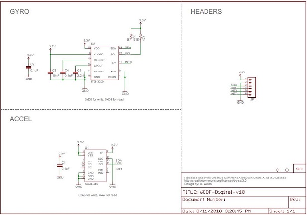
Sparkfun.com offers a convenient and tiny board that has both an accelerometer and a gyroscope on it: IMU Digital Combo Board - 6 Degrees of Freedom ITG3200/ADXL345. Below is the schematic of our circuit board that includes the sensor chip, a level converter chip, a receiver, pins for motors and header sockets for our MCU board and an LCD for debugging purposes only.
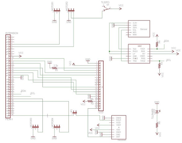
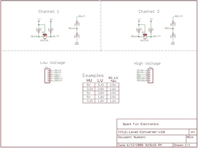
Level converter
Our MCU is powered up by the 7.4V battery and outputs 5V. The IMU that we use takes 3.3V input, so we needed a voltage level shifter (from 5V to 3.3V). Logic Level Converter BOB-08745 from sparkfun.com is very cheap and does the job. Even cheaper way would be using three diodes instead of the level converter.
Brushless servo motors
Although it is harder to control brushless motors compared to brushed motors, we decided to use brushless servo motors for the following benefits:
- More torque per weight
- More torque per watt (increased efficiency)
- Increased reliability
- Reduced noise
- Longer lifetime (no brush and commutator erosion)
- Overall reduction of electromagnetic interference (EMI)
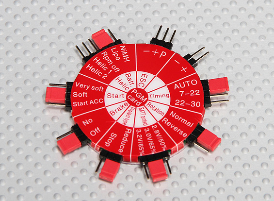
The easiest way to program the motor controllers is to use one of those HobbyKing ESC Programming Cards as shown below.
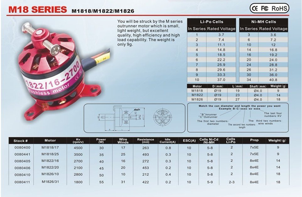
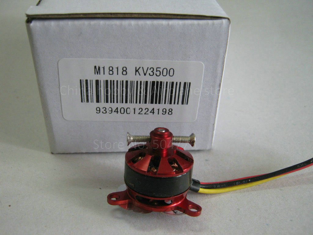
The following picture shows the motor specifications in detail. Here we can see that the motor M1818/25 draws 35 Watt. This means that using a 2 cell (7.4v) battery the motors will draw 4.73 Amp. This means that the 1050mah battery will last for 1.05/(4.73*4)= 3 minutes with the motors at full speed. Assuming that the motors need to be at half speed for the quadcopter to hover, the total flight time will be between 3 to 6 minutes.
Software design
Our overall program is depicted in the diagram below:
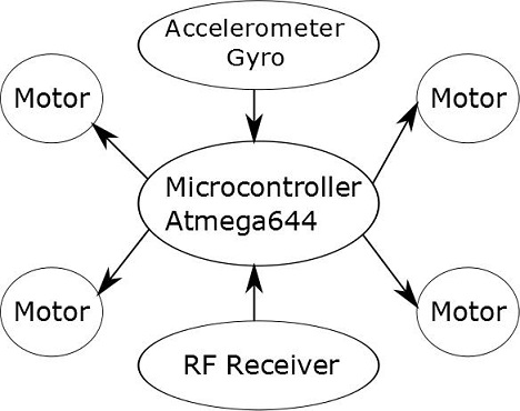
We have four major tasks that we perform constantly as below:
- Read Gyro at 200Hz
- Read Accelerometer at 200Hz
- Flight controls at 100Hz
- Read receiver at 50Hz
The software for this project was based on the online project called de ArduCopter. This ArduCopter is a Arduino based quadcopter. The fact that the ArduCopter existed assured us our project was feasible. This online quadcopter project is OpenSource, this means that our use of their code still has to be OpenSource.
In order to transfer the ArduCopter code into the Atmega644 microcontroller it was necessary to convert the Arduino libraries. This was the most complicated part of the project, however it was also the part that benefited us the most.
SerialHardware.h, Servo.h and Device_I2C.h were the most imported libraries that we converted to the atmega644. The Servo.h alowed us to create several PWM signals of 50Hz with a pulse width of 1ms to 2ms. This library was very optimized and it permited for 12 of these PWM signals to be controlled with a single 16 bit Timer with a resolution of 2us. This was very usefull since the atmega644 has only 6 PWM outputs hardwired and with a much smaller resolution and higher frequencies. Controlling speed on the motor controllers is as easy as controlling a servo (after they are programmed).
SerialHardware.h was a simple uart interface, however converting the library allowed us to minimally alter the Arducopter code in order for it to work in the atmega644.
Finally Device_I2C.h is a library that gives functions that use protocol for two wire interface. This was used to communicate with the sensor board. This library allowed us to use simple read and write functions to the I2C lines without worrying about the low level interface, in main().
In the project folder it is possible to see the following files:
- AQMath.h
This file contains all the functions that perform matrix operations, i.e matrixInverse3x3(). These operations are going to be used when calculating the quadcopter kinematics.
- Accelerometer.h
This file contains the header functions for the next file, this was done so that for the Arducopter to be flexible to different accelerometers, the actual functions will be in the Accelerometer_ADXL345.h.
- Accelerometer_ADXL345.h
This file contains the functions that initializes the accelerometer using the I2C protocol, it also contains all functions that interact with the accelerometer, including measureAccel() and other usefull ones like evaluateMetersPerSec(). This last functions depends not only on the acceleration but also the time difference between readings.
- AeroQuad.h
All the general variables are defined in this file, this is used to isolate the main code from the variables associated with the quadcopter caracteristics, and the time variables.
- DataStorage.h
This file contains the functions that read and write to EEPROM including functions that read and write floats. This allows for the program to keep the PID values after pwer cycling, allowing for the quadcopter to always stay calibrated.
- Device_I2C.h
This file contains all the functions necessary to implement a two wire protocal, allowing for the accelerometer and gyroscope functions to call the sensors without worrying about the communication protocol.
- FlightCommandProcessor.h
This file contains a single function called, readPilotCommnads, this functions ensures that the motors are only armed under certain conditions and also that some of the controllers configuration activate configuration mode.
- FlightControlProcessor.h
This file copntains the most important functions for the good functioning of the quadcopter, it contains all the functions that correct the error for the motor speeds. It also ensures that the motors signals never go over or under the 1ms to 2ms pulse width.
- FlightControlQuadX.h
This file defines the physical layout of the quadcopter, numbering the motors in such a way that the X, Y and Z axis align correctly.
- FourtOrderFilter.h
This file contains the functions that preform a Chebyshev fourth order filter for the sensor values. This is done so that the vibrations are damped allowing for a smoother flight.
- GlobalDefined.h
This file only contains the axes definition so that throughout the project they can be mentioned as 'XAXIS' instead of a number.
- Gyroscope.h
This file contains the headers for the following two files. This was done so the Gyroscope in the Arducopter can be interchangeble.
- Gyroscope_ITG3200.h
This file contains all the functions that interact with the gyroscope. It contains functions like calibrateGyro(), so that the gyroscope is initialized properly.
- Gyroscope_ITG3200Common.h
This file contains the common function between gyroscopes, containing the actual measureGyro(), which returns the actual gyro values. It also contains functions to detect the gyro drift compensating with the accelerometer information.
- HeadingHoldProcessor.h
This file contains all the functions that ensure a stable yaw.
- Kinematics.h
This file contains the files that convert all the speed and rotation to actual psysically meaningfull values. This means that for example the values that come from the accelerometer will be converted to meters per second squared.
- Kinematics_ARG.h
This file also contains very important functions that stabelize the quadcopter. These functions convert the arguments for flight control into real physical values already filtered and processed so that the quadcopter stabelizes properly.
- Motors.h
This file contains the declation of the motor numbers and is the header for the functions that write to the motors. The actual functions will be on the next file. This is done so that the method used to write to the motors is indepented from the actual function.
- Motors_PWM.h
This file contains the motor control functions. These functions take advantage of the servo.h file to create the pwm necessary to control the motor. It is also in this file that internal clock ISR is written, meaning that every millisecond the clock will increment a variable called AbsoluteTime, this variable will be used by most functions as an internal clock. It will only overflow every 71 minutes.
- PID.h
This file contains all the PID calculations. This was taken from the arduino.cc page and converted for the Atmega644, based on lab 4 from ECE 4760.
- Receiver.h
This file defines all the initial values for all the receiving parameter from the RF receiver. It also includes all the global variables that are to be affected by the human interface, like Throttle, X, Y and Z axes speed.
- twi.h
This file contains all the low level functions that allow the microcontroller to communicate using the two wire interface. This functions is included in the previous Device_I2C.h. The Device_I2C is a high level interface so that in the main code we didn't need to worry about the lower details simplifying the code.
Back to topWireless communication protocol
The transmitter and the receiver that we used are TWS-BS-6 and RWS-374-3. Their frequency range is 434MHz.
We send 4 bytes of information at a time. Checksum is (Addr+Data) and when the receiver receives 4 bytes, it adds the second and the third bytes and compares the sum to Checksum to see if there was any error in the transmission.
Sync | Addr | Data | Checksum
We send only 15 distinctively different kinds of data to control the motors. 0, 1,
8, 9 for the numerical value of the speed of a motor, Y for yaw, P for pitch, R for roll, U for up and down, and / for separating data sets for an each motor. For example, we can send 1U32/2Y53/3R119/4P54. For an accurate transmission, its better to send a byte that is balanced with the same number of 0s and 1s. However, this scheme chops the transmission rate by half because to send a byte of 10010101, we need to break it into two four bits and pad them with 0110 and 1010 respectively (for example, complements of 1001 and 0101) and send two bytes, 10010110 and 01011010. To avoid this overhead and still guarantee a high accurate transmission rate, we cleverly chose bit patterns for 15 data that are perfectly bit-balanced.