Cornell University ECE4760
Charge Time Measurement Unit (CTMU)
PIC32MX250F128B
CTMU
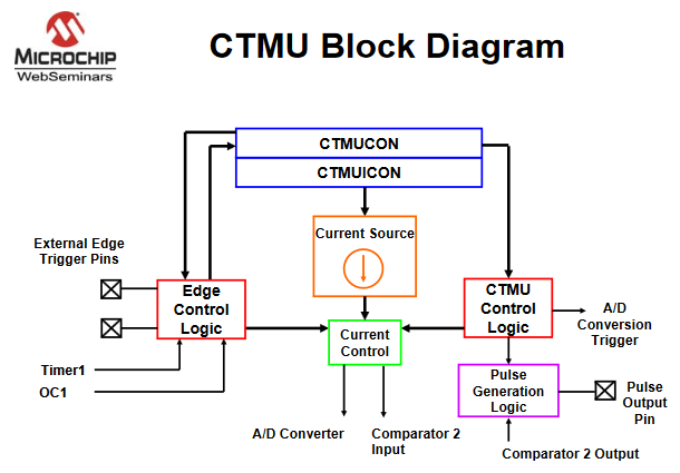
The CTMU is basically a settable current source, with flexible triggering, and a direct connection to the ADC for measuring voltage. It can be used to measure resistance, capacitance, inductance, very short times (think LIDAR), and generate a pulse train which is not synchronized to the CPU clock (entropy source?). From the PIC32 reference manual, section 37: "The CTMU can be used for high resolution time measurement, measure capacitance, measure relative changes in capacitance or generate output pulses with a specific time delay. The CTMU is ideal for interfacing with capacitive-based sensors. See also AN1375 What You Can Do with the CTMU
Possible uses are:
- Up to 32 channels available for capacitive or time measurement input
- Time measurement resolution of one nanosecond
- Integrated temperature sensing diode
- Time delay of external or internal signal asynchronous to system clock (entropy source?)
- On-chip precision current source with:
- Triggered by external or internal sources
− Timer1, output compare, software trigger
− Rising Edge, Falling edge combination of one or two external pins
asynchronous to system clock
- Selection of edge or level-sensitive inputs
- Control of response to edges
- Control of current source during auto-sampling
- Four current source approximate settings 0.55, 5.5, 55, 550 micoamps.
The CTMU current source is always used in conjunction with other hardware to perfrom some function.
See also AN1375 What You Can Do with the CTMU
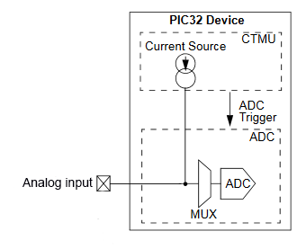
- The CTMU works in conjunction with the Analog-to-Digital Converter and a timer to provide up to 32 channels for time or charge measurement. The analog input could be attached to a resistor you want to measure, or a capacitance touch sensor. For the touch sensor you would turn on the CTMU for a fixed time (fixed charge) and measure the resulting voltage, which would be proportional to charge/capacitance.
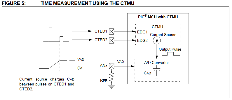
- The CTMU works with the Analog-to-Digital Converter using the A/D sample and hold capacitor to measure the time between to gate pulses.
Examples
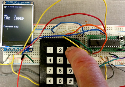
- Measure Resistance.
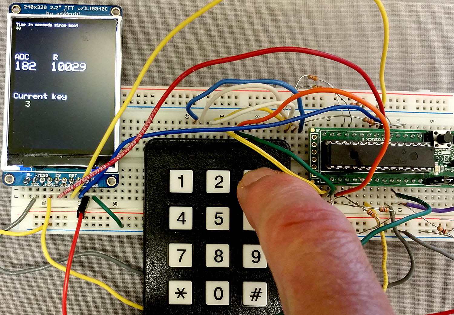
The first example uses the keypad to choose a curent level and the TFT display to diplay raw ADC values for testing, and a computed resistance. A resistor was connected between the AN9 analog input, pin 26 on the PDIP package, and ground. The current source connects internally to the ADC multiplexer and drives the analog input pin, so that the voltage read by the ADC scales with the resistance. Setting the CTMUCONbits.IRNG bit field from 0 to 3 sets the current to {550,0.55,5.5,55} microamps respectively. There is also a trim bit field for fine current adjustment. The image below shows the result of applying current-level 3 (55 microamps) to a 10K resistor. Going to the next higher current saturates the ADC. Going to the next lower current works, but is less accurate because of limited ADC resolution. (project ZIP).
Resistance is calculated as:
R = (float)(raw_adc-adc_zero[key_pressed])/1023. * 3.3 / I_set ;
or converted to the meaning of each term:
    R =
    (ADC_reading - zero_offset)/(ADC_full_scale) * Vref/ current
The zero resistance offset was obtained by shorting the ADC pin to ground. This number will probably be different for each chip.
The current was taken as the nominal values from the data sheet TABLE 29-39. Calibration is probably necessary for accurate work.
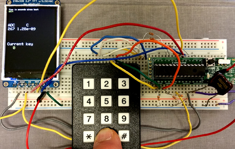
- Measure Capacitance.
The second example displays the capacitance from AN9 (pin 26 on PDIP package) to ground. With no cap attached, the white board, plus ADC sampling cap, adds up to about 18 pf. Uncalibrated accuracy seems good. a 1300 pf, 2% cap reads 1280 pf. The ADC sample/convert functions have to be manually controlled in the program. (project ZIP)
The steps are:
- The ADC sample command,
AcquireADC10(), closes the internal sample switch to connect the input pin to the internal ADC sampling cap.
- The CTMU internal discharge switch is closed to short charge to ground from all the capacitance.
- Pause the thread for approximately one millisecond.
- The CTMU discharge switch is opened, then the CTMU internal charge switch is closed using
CTMUCONbits.EDG1STAT = 1
- Wait for a precise time interval, in this case 2 microseconds, for charge to accumulate on the capacitor under test.
- The CTMU internal charge switch is opened using
CTMUCONbits.EDG1STAT = 0 to stop charging.
- The ADC convert command,
ConvertADC10(), opens the sampling switch and starts the actual conversion to determine cap voltage.
- Wait for the ADC conversion to complete.
- Read the ADC using
ReadADC10(0)to get the raw ADC conversion.
- Compute C=q/V or
C = (Set_current) * (current_time_interval) / ((float)(raw_adc)/ADC_max * Vref)
An example
is shown below using the 1300 pf capacitor and a drive current of 550 microamps chosen by pushing button zero..
- Macros for i/o definitions
It is nicer to define some macros to make the CTMU use easier. But note that this set is not complete.
I have not yet written macros for external triggering.
These are sufficient for the two examples above.
// hardware-available current levels

    #define CTMUuA550 0 // 550 microamps

    #define CTMUuA55 3 // 55 microamps

    #define CTMUuA5point5 2 // 5.5 microamps

    #define CTMUuApoint55 1 // 0.55 microamps

    // turn on/off the current source


    #define CTMUenable CTMUCONbits.ON = 1;

  #define CTMUdisable CTMUCONbits.ON = 0;

  // use one of the 4 current levels defined above for
CTMUcurrentSet

    #define CTMUcurrentSet(current) CTMUCONbits.IRNG=current;

    // dissharge the cap under test, if necessary.

    // shorts the current source to ground

    #define CTMUdishargeON CTMUCONbits.IDISSEN=1; // I source grounded

    #define CTMUdishargeOFF CTMUCONbits.IDISSEN=0;

    // edge state 0/1 off/on

    // to used to quickly gate the current source -- READ the MANUAL!


    #define CTMUedge1State(binary) CTMUCONbits.EDG1STAT = binary;

  #define CTMUedge2State(binary) CTMUCONbits.EDG2STAT = binary;
These definitions are used in a modified capacitance code.
The code also uses the i/0 pin pull-down macros described on the TFT/keypad page
Copyright Cornell University
October 22, 2018