Cornell University ECE4760
Keypad
PIC32MX250F128B
Keypad
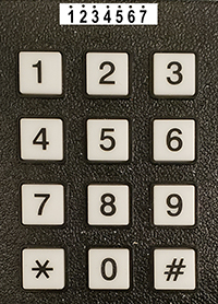
A small keypad is a useful input device. Adding a 12 key keypad (0 to 9 with * and #) requires seven i/o pins. The seven pins can be connected directly to the PIC32, with some careful planning on i/o pin use. There is more i/o pin flexibility if you connect the keypad to the port expander. I strongly suggest that you use the port expander. There is much more information on the port expander on the development board page. The physical connections to the keypad are shown below. The line of numbers across the top of the image represents the seven connections on the underside of the keypad. Each keypad button shorts one row-connector pin to one column-connector pin.
Connector              Port Expander     PIC32 (not recommended)
Pin 1 --- button row 1 (300Ω to pin Y0) (300Ω to pin A0)
Pin 2 --- button row 2 (300Ω to pin Y1) (300Ω to pin A1)
Pin 3 --- button row 3 (300Ω to pin Y2) (300Ω to pin A2)
Pin 4 --- button row 4 (300Ω to pin Y3) (300Ω to pin A3)

Pin 5 --- button col 1 (pin Y6)(note a)  (pin B7)(note b)
Pin 6 --- button col 2 (pin Y5)(note a)  (pin B8)(note b)
Pin 7 --- button col 3 (pin Y4)(note a)  (pin B9)(note b)

(a) Turn on port expander i/o port internal pullup resistors.
(b) Turn on PIC32 i/o port internal pulldown resistors.
Keypad using port expander i/o
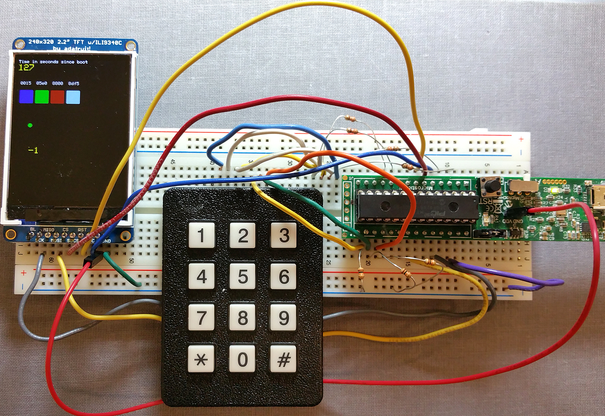
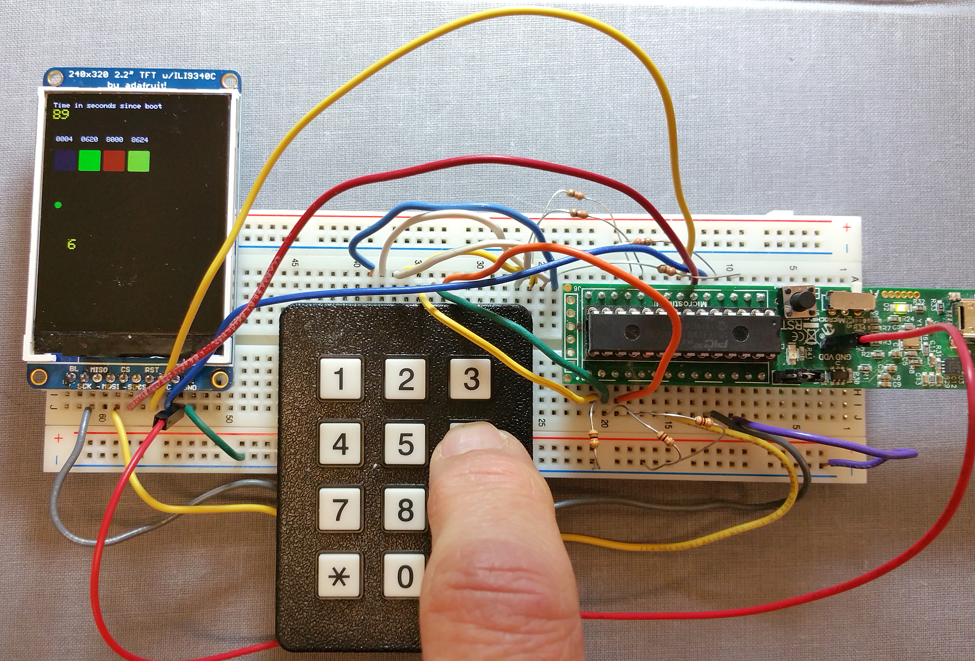
The example uses the port expander library (details below). Download the ZIP and the source code which implements the keypad scanner using the port expander on the big board pinout shown on the left below. Included in the ZIP file is the portexpander_brl4.h and portexpander_brl4.c corrected and extended for the big board. This example adds to Sean's version by allowing the DAC and port expander to share an SPI channel without conflict (except timing). The port expander docs name the two 8-bit ports A and B, but to avoid confusion with the PIC ports of the same name, Sean refers to the expander ports as Y and Z on the big board and in the interface library. The keypad is connected to port pins Y0 to Y6. Y0 to Y3 are driven as outputs, while Y4, Y5 and Y6 are inputs with pullups turned on (there are no pulldowns on the expander). The scanner logic has to be modifed for active-low outputs, but the scanner output is the same as before. The scanner returns 0 to 11 for a valid key, and -1 if there is no valid keypress. Since the DAC is driven from an ISR (and is on the same SPI channel), and since the keypad takes several SPI interactions to complete a write-read cycle, it is necessary to define a critical section in the code to disable the ISR for a few microeconds while write/reading the port expander SPI channel.
Keypad Scanner/Decoder:
(1) Shift one zero value (active low) through the 4 input lines ( Y0 to Y3).
(2)
Y4, Y5 and Y6 all high implies no button push -- bit-wise and the Y port with 0x70 to isolate the three keypad input bits.
Ignore the shift key (Y7 input) because pressing the shift key alone is not valid.
(3) If the
result of the and is not equal to 0x70, then there must have been a button push.
(4) If there was a button push start trying to match it to the scan table.
(5) Scan table includes shift key input and returns -1 if there was no (or an illegal) keypress.
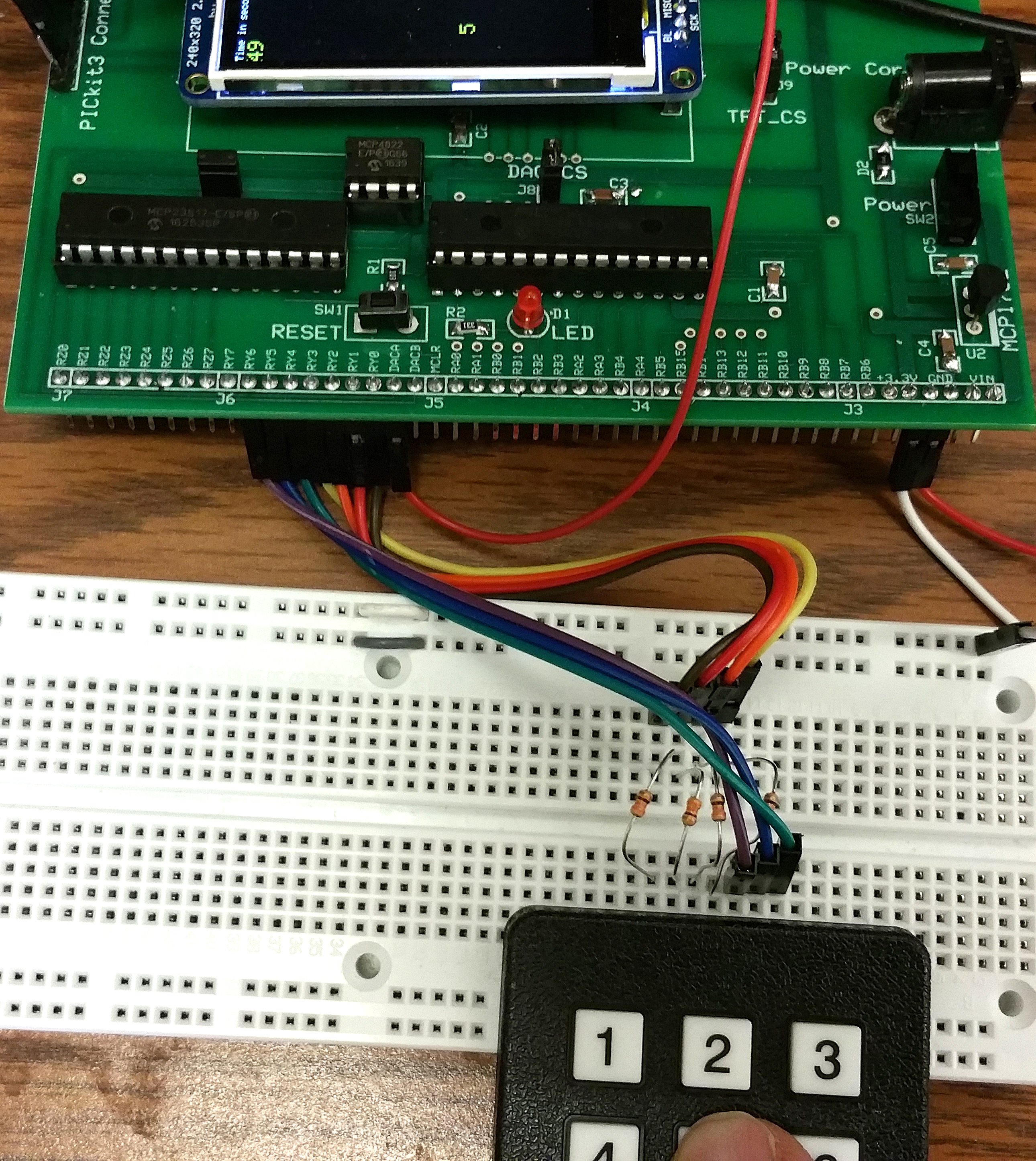
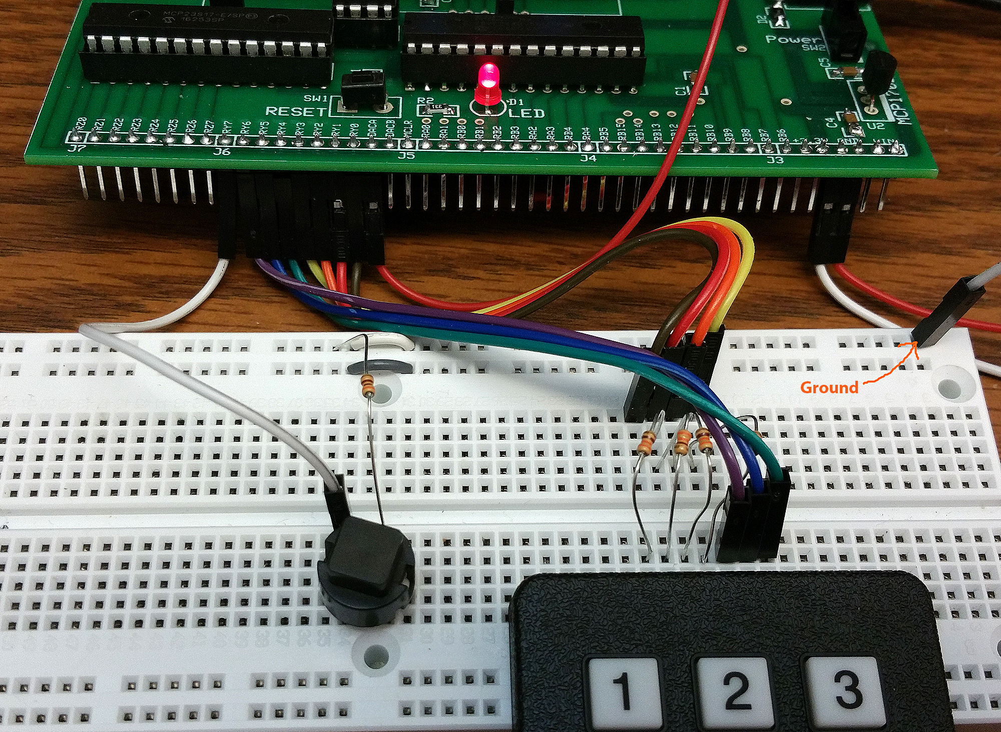
The image on the right includes an extra switch which acts as a shift-key for the keypad and which is connected to Y7 (with pullup turned on). The code supports 24 unique button codes and displays them on the TFT for testing using the printline function. The switch is connected through a 300 ohm resistor to ground, when pushed, and is pulled-up internally. If you float the input, the code behaves in the same way as the keypad with no shift key attached.
>>>DO NOT USE!
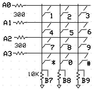
Keypad using PIC32 i/o
Each switch connects one row wire to one column wire. Connection scheme used in the test code is shown below. 300 ohm resistors protect the outputs from short circuits when multiple switches are closed. The 10K pulldown resistors provide an input source when the switches are open. The code displays the button label when a button is pressed, and -1 when no button is pressed. If you add one line of code, you can eliminate the three 10k pulldown resistors by turning on internal pulldowns. The poorly documented CNPDB register (Change Notice Pull-down Enable B) selects input bits to pull down. Setting
CNPDB = BIT_7 | BIT_8 | BIT_9
in the keypad thread pulls down B7, B8, and B9. To be safe, you should probably clear the CNPUB register to turn off pull up resistors.
If you include the following macros:
// PORT B

  #define EnablePullDownB(bits) CNPUBCLR=bits; CNPDBSET=bits;

  #define DisablePullDownB(bits) CNPDBCLR=bits;

  #define EnablePullUpB(bits) CNPDBCLR=bits; CNPUBSET=bits;

  #define DisablePullUpB(bits) CNPUBCLR=bits;

  //PORT A

#define EnablePullDownA(bits) CNPUACLR=bits; CNPDASET=bits;

  #define DisablePullDownA(bits) CNPDACLR=bits;

  #define EnablePullUpA(bits) CNPDACLR=bits; CNPUASET=bits;

#define DisablePullUpA(bits) CNPUACLR=bits;
Then you can just write
EnablePullDownB( BIT_7 | BIT_8 | BIT_9);
ZIP of project.
Older versions of the documentation -- ignore this
The physical connections for servral styles of keypad are shown below. You probably will want to use the
12-key models.
Connector:  top:8-pin      top:9-pin   bottom  12-key
Pin 1  ---- row 1 2 3 A    col 1       col 1    row 1 (pin A0)
Pin 2  ---- row 4 5 6 B    col 2       col 2    row 2 (pin A1)
Pin 3  ---- row 7 8 9 C    col 3       col 3    row 3 (pin A2)
Pin 4  ---- row * 0 # D    col 4       col 4    row 4 (pin A3)

Pin 5  ---- col 1 4 7 *    row 1       row 1    col 1 (pin B7)
Pin 6  ---- col 2 5 8 0    row 2       row 2    col 2 (pin B8)
Pin 7  ---- col 3 6 9 #    row 3       row 3    col 3 (pin B9)
Pin 8  ---- col A B C D    row 4       row 4    ----
Pin 9  ----              (NO CONNECT--common)

(a) Each switch shorts one row to one column. When in doubt, get the ohmmeter!
(b) On the 9-pin models, do not connect the common lead.
For DDS lab:
pins 4,5,6, 22 and 25 (RB0, RB1, RB2, MOSI1, SCLK1) pin 26 pin 14, but remember to set #pragma config JTAGEN = OFF, DEBUG = OFF
pin 11, but remember to set #pragma config JTAGEN = OFF, DEBUG = OFFCopyright Cornell University September 6, 2019