Below is a cropped screen capture of the running system showing the RTC which was set from the NTP time stamp.
Cornell University ECE4760
Using LWIP with VGA
Pi Pico RP2040
VGA driver and LWIP
Both the VGA driver written by Hunter Adams (and converted to 256 colors by Bruce) and the LWIP supplied as part of the C SDK use significant hardware to accelerate operations. The VGA driver uses 4 DMA channels and all 4 state machines in one PIO. The LWIP uses 2 DMA channels and two PIO state machines. LWIP defaults to PIO1 (see cyw43_bus_pio_spi.c), so the VGA must use PIO0. The LWIP uses the claim mechanism to grab DMA channels. This means that any unused channel may be grabbed. The VGA driver was modified to use the claim system so that it does not step on the channels used by LWIP. Once this small change was made, the two libraries played nicely together.
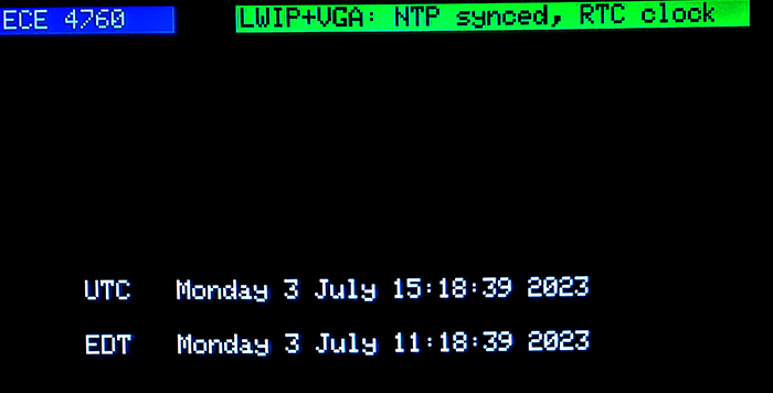
Real_time clock (RTC) display on VGA
Below is a cropped screen capture of the running system showing the RTC which was set from the NTP time stamp.
The description of VGA and connections are here, with more detail on Hunter's page.
You also need a serial connection to Putty or another terminal.
The description of the RTC and serial commands to set the clock are here.
The structure of the program is built around Protothreads, with a thread to get the network time, a thread interfacing to a serial terminal for debugging and commands, a graphics thread and a blink thread just to show that the networking had not killed the threader. Actual low level packet receive is performed by an ISR set up by LWIP. The NTP code is modified slightly from the picow examples repositiory, then converted to run in a thread, with a control semaphore signaled by the serial thread.
Code, ZIP project
Note that the code has defines for WIFI SSID and password that must be specified for your system.
Also note that date is not handled very well if the actual UTC is less than the local time zone.
Copyright Cornell University July 4, 2023