Simple polling.
The simplest way of using the ADC is to start a conversion in software, wait until it is done, read it, and repeat. This program reads the ADC, starts a conversion, prints the value of the last conversion and repeats. The program does not explicitly poll the ADC completion bit (ADCSR.6 goes low when conversion is complete) because the print takes longer than the actual A/D conversion, so the conversion always finishes before the ADC is read again. The program sets up the ADC to read left-adjusted, 8-bits only, using an external Vref. On the STK500 board, the Vref jumper must be mounted.
Differential input with gain.
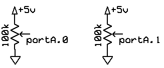
This program uses polling, but turns on the internal differential amplifier in the Mega32. The gain is settable to 1, 10 or 200. The output of the ADC in differential mode is a 2's complement number representing the voltage diffenence between two analog input channels. The example is set up to be 10*(channel1-channel0). Voltages at both inputs have to be between zero and Vref. Clearly, if you are using gain, you must make sure that the amplified difference is also between -Vref and Vref. The test inputs are shown below. Each potentiometer was adjusted to the middle of its range initially. Calibration of the ADC and internal differential preamp was verified with a voltmeter between the two wipers of the potentiometers.
Another program uses differential input differently. The raw 10-bit ADC value is converted to a 8:8 fixed-point number, scaled so that the integer part of the number reads in millivolts from -127 to +127 mV. The conversion to fixed point is done using a union to avoid multiplies or shifts. Timer0 runs the PWM at 62,500 Hz to reduce filtering requirements at audio frrequencies. The ADC is sampled at 7812 Hz using a timer1 compare-match ISR. The PWM output is scaled so that a 100 mV difference at the inputs produces a one volt shift in the PWM voltage.
ADC ISR-driven, low noise, 10-bit conversion
This program uses interrupt driven A/D conversions to get low noise for 10-bit accuracy. During the conversion the MCU is put into ADC noise reduction sleep mode. This mode turns off most of the MCU to cut down on digital noise. The only way to wake it up is for the ADC to finish a conversion. When the program enters the while(1) loop it encounters an assembler sleep command. The MCU is disabled, the conversion is automatically started and runs, then the MCU is restarted and immedately executes the ADC ISR. Then execution resumes after the sleep command. Of course, to actually get 10-bit accuracy, you have to minimize outside interference, such as 60 Hz noise. If you don't need more than 8-bit accuracy, then you don't need to put the MCU to sleep. You can just define an ADC ISR, turn on the ADC interrupt, and the MCU will enter the ISR when the conversion is finished.
Very often it is desirable to take analog readings at uniform sample rate. This program uses timer0 to produce a PWM output (see below) of a lowpass filtered ADC input. The PWM is running at 7812 samples/sec. The ADC input runs at a slower rate for testing and printing to the serial port, but can run at full 7812 samples/second also. See the DSP page for more details on filtering.