Lab 0
ECE 4760, Adams/Land, Spring 2021
The purpose of the first lab section is to get familiar with this course's infrastructure and workflow.
This is the only lab of the semester for which you may leave early if you finish early. This is also the only lab that will be completed individually. You must demonstrate the provided example code running on a PIC32 in the lab and producing a sound through Zoom.
Lab 0 tasks:
- Access Cornell's VPN
- Establish a Remote Desktop connection to a Lab PC
- Download, build, and program the PIC32 with some example code
- Join the Zoom call from the Lab PC, demonstrate audio coming from the PIC32 through Zoom
- Download and run the Python script associated with the example code
Webpage Table of Contents
Accessing Cornell's VPN
Please follow Cornell's guide for setting up and connecting to Cornell's VPN linked here. You will only need to set this up once.
Establishing a Remote Desktop connection to a Lab PC
There are two sets of instructions below. One for Mac users, and the other for PC users. Accessing the Lab PC's requires permission from CIT. If you are denied access, please let me know so that I can verify that your netid is on the approved list.
Remote Desktop Connection via PC
- Logon to Cornell's VPN using your netid and password
- Open the Remote Desktop Application
- Expand the "Show Options" menu as shown below
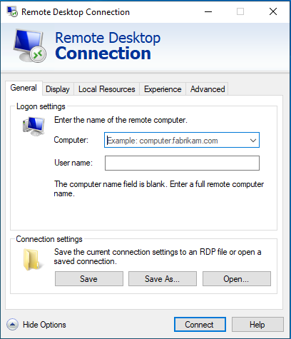
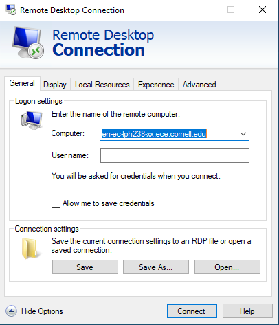
- Enter the name of your Lab PC (this will be provided to you on the day of the lab, and your group will be assigned a particular PC to use all semsester). The name of the PC will be of the form
en-ec-lph238-XX.ece.cornell.eduwhere XX will be the number of your particular PC, different for each group. Do not log on to a PC that isn't assigned to you.
- Navigate to the "Local Resources" tab and click "Settings" for Remote audio.
- Make sure the Remote audio settings are configured as shown below.
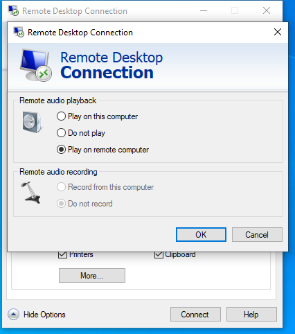
- Click "Ok" and then "Connect." Login with your netid and password.
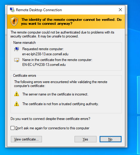
- The warning message shown below may open. If so, just click "Yes" to connect to the PC.
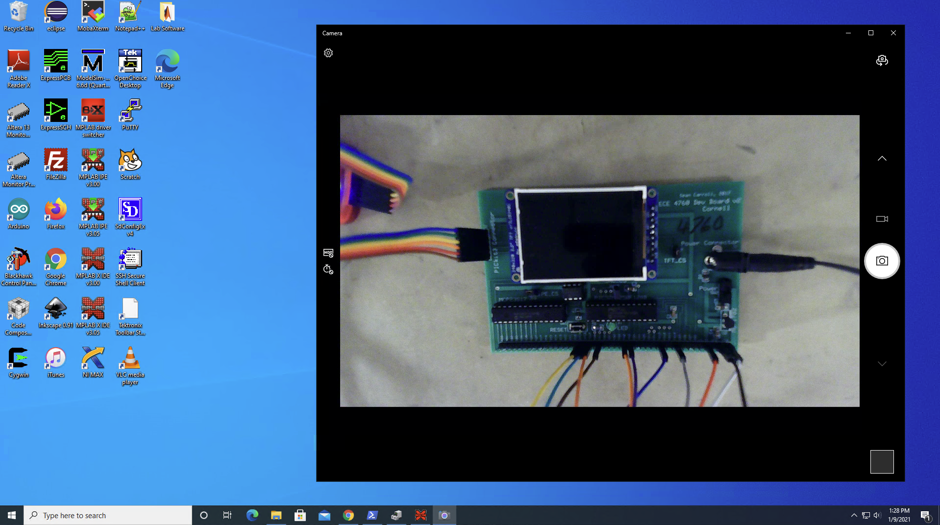
- You are now in control of the Lab PC. Open up the Camera application to see the hardware connected to your PC.
Remote Desktop Connection via Mac
- If necessary, install the Microsoft Remote Desktop application, available at this link.
- Logon to Cornell's VPN using your netid and password
- Open the Remote Desktop Application
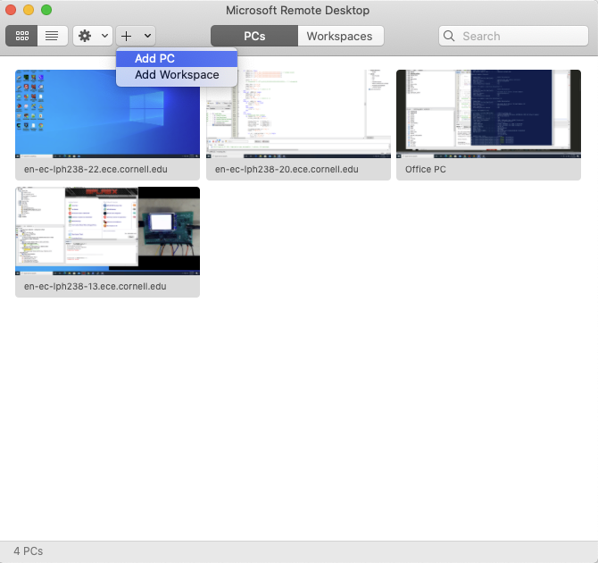
- Click the "+" button in the top toolbar, and then click "Add PC" as shown below
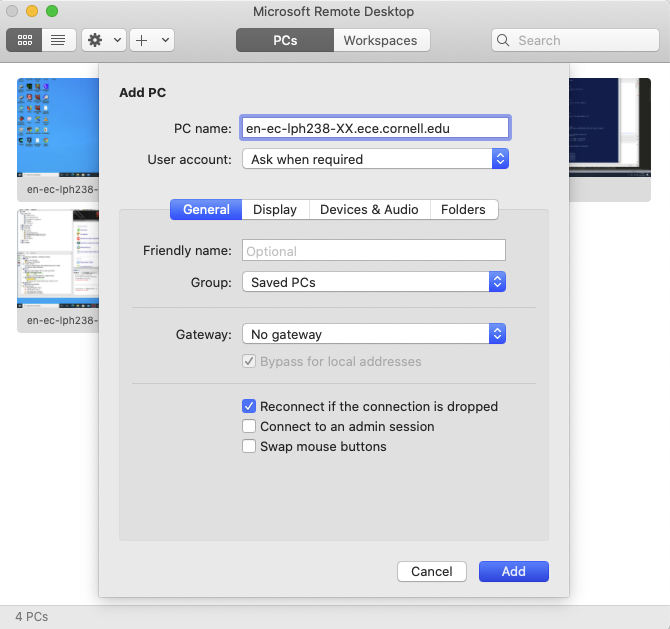
- In the window that appears, enter the name of your Lab PC (this will be provided to you on the day of the lab, and your group will be assigned a particular PC to use all semsester). The name of the PC will be of the form
en-ec-lph238-XX.ece.cornell.eduwhere XX will be the number of your particular PC, different for each group. Do not log on to a PC that isn't assigned to you.
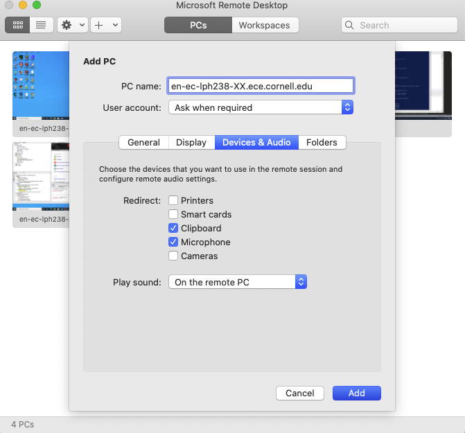
- Navigate to the "Devices & Audio" menu, and make sure that it is configured as shown below. In the "Redirect" menu, both Clipboard and Microphone should be checked. In the "Play Sound" dropdown menu, "On the remote PC" should be selected.
- Click "Add" and your PC will appear in the main window. Double-click and login using your netID and password.
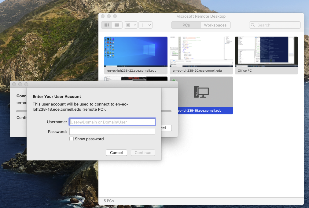
- Click "Continue" and the desktop for the lab PC will appear. You are now in control of the Lab PC. Open up the Camera application to see the hardware connected to your PC.
Creating a new project in MPLABx
- Open MPLAB X IDE v.3.05 on the desktop. Note that there may be more than one version of the MPLAB X IDE installed. Make sure you open v. 3.05.
- In the window that opens, navigate to
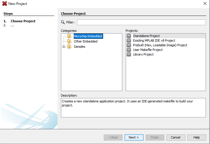
File --> New Project. - Select the "Microchip Embedded" category and "Standalone Project," as shown below.
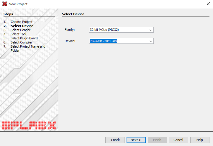
- Select the "32-bit MCUs (PIC32)" Family from the dropdown menu, and then select the device "PIC32MX250F128B." Then click Next.
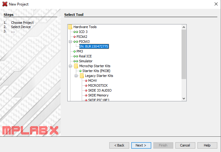
- Select the PICkit3 attached to your particular lab pc (the SN will be different, but it will appear as shown below).
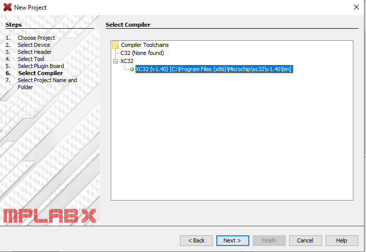
- Select the XC32 (v 1.40) compiler, as shown below.
- Give your project a name. Here, I've called it "Demo."
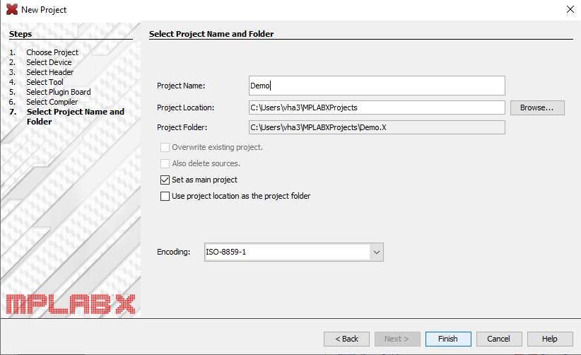
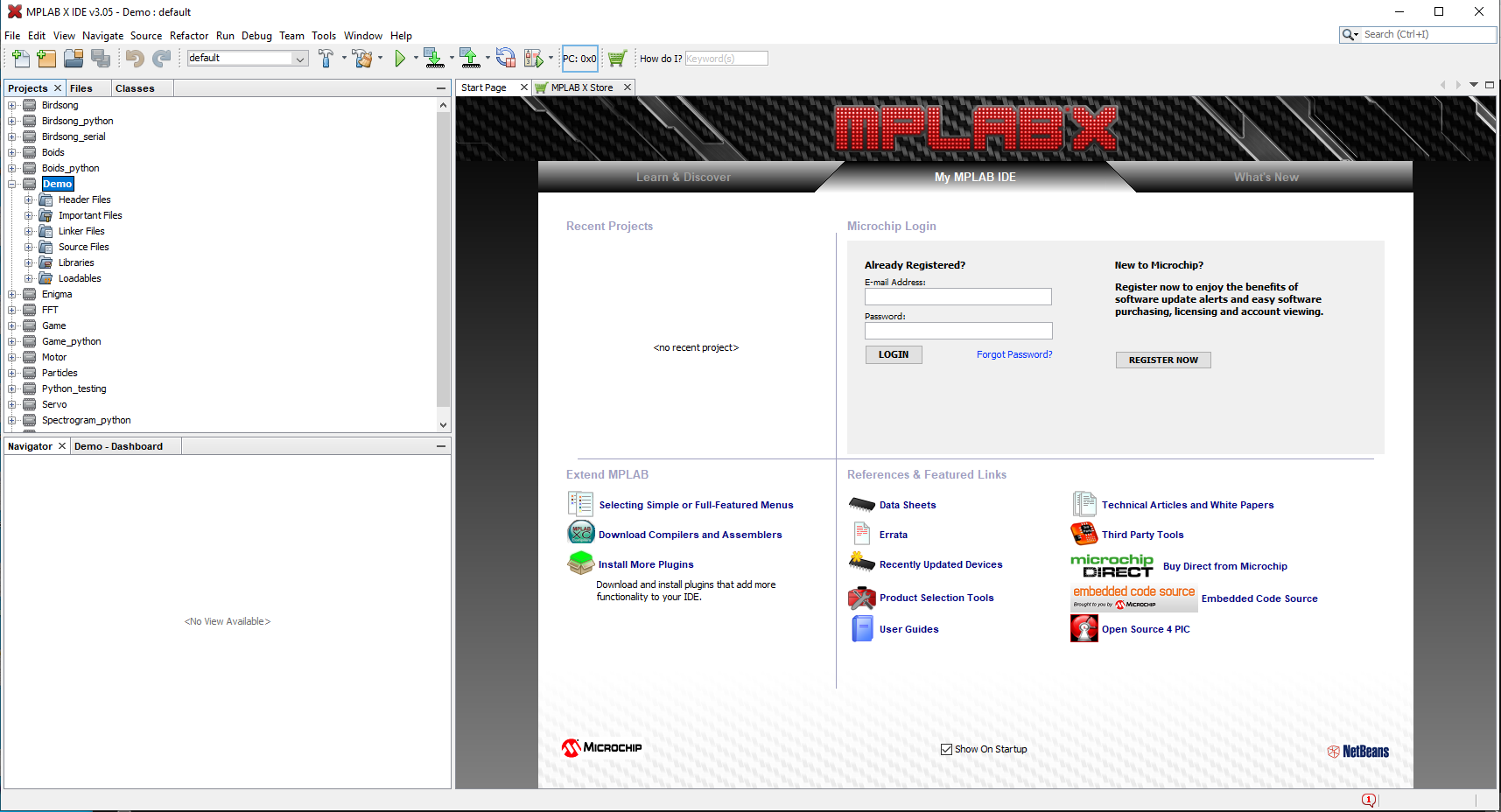
- Click "Finish." Your project will then appear in the project navigator on the left. You'll see that there are a number of folders associated with your project, including "Header Files" and "Source Files." We will add demo software to these two folders in the subsequent section.
Downloading and building some example software
- Download the zipped demo project files from this link (also available on the Remote Interfaces webpage. Unzip the file, and you will find that it contains a bunch of c header and source files.
- In the MPLABX IDE, right-click the "Header Files" folder in the project navigator on the left side of the screen, and then select "Add existing item."
- In the window that pops up, navigate to the folder which contains all of the demo code.
- Select all header (
.h) files and click "Select." - If you expand the "Header Files" folder, it should now contain:
config_1_3_2.h
port_expander_brl4.h
pt_cornell_1_3_2_python.h
tft_gfx.h
tft_master.h - Similarly, right-click the "Source Files" folder and select "Add existing item."
- Navigate to the folder that contains all of the demo code.
- Select all of the source (
.c) files and click "Select." - If you expand the "Source Files" folder, it should now contain:
glcdfont.c
port_expander_brl4.c
SECABB_python_target_v4_1_3_2.c
tft_gfx.c
tft_master.c
(which one containsmain?) - Click the hammer icon in the top toolbar to build the project. A series of warnings may be thrown, and then it should indicate "BUILD SUCCESSFUL" in green font.
Programming the PIC
- In the top toolbar, click the down-arrow icon to Make and Program Device Main Project. Programming status will be displayed at the top of the screen.
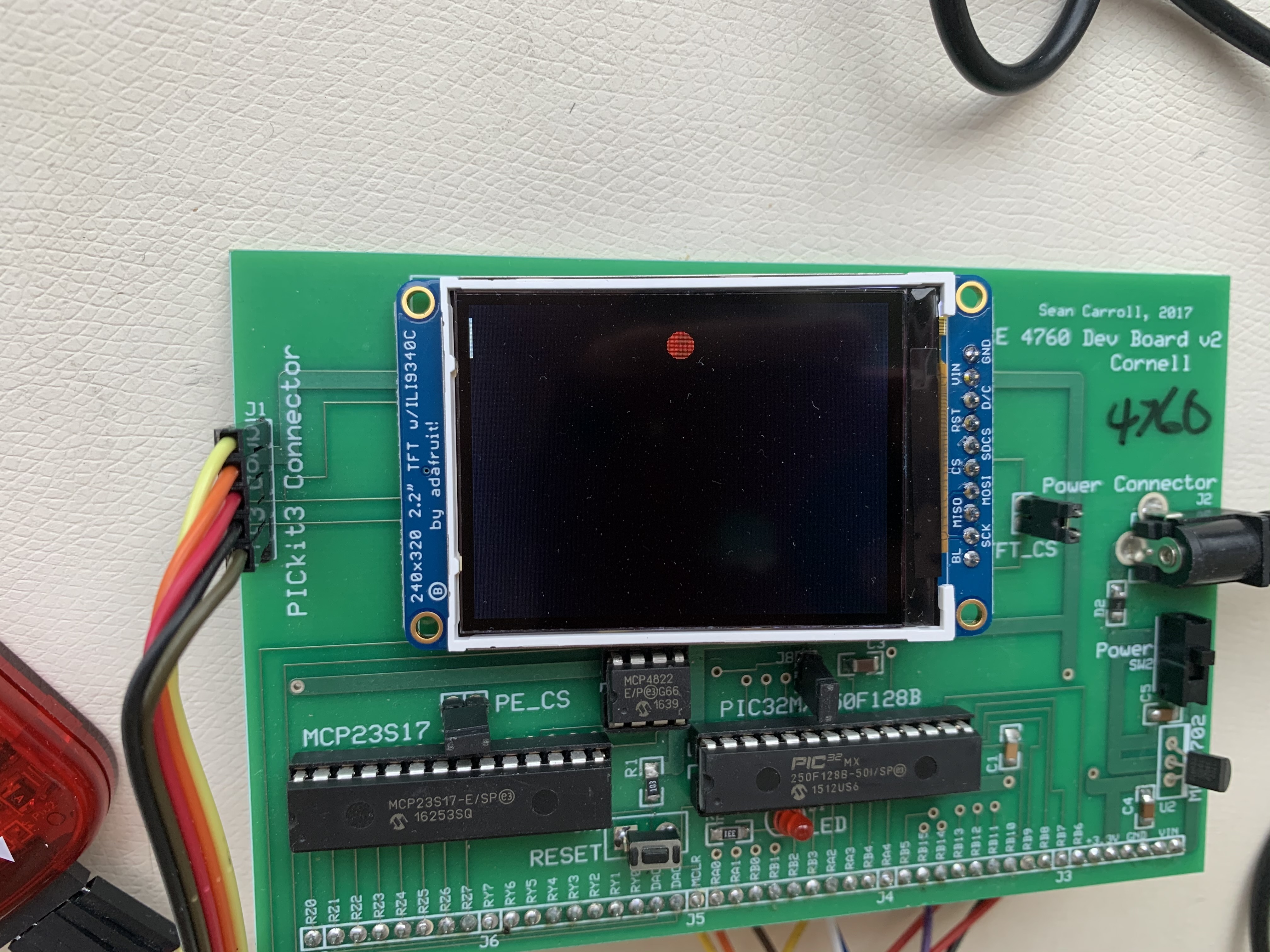
- When the device is finished programming, open the Camera application. The TFT display should show a line and circle, as pictured below:
- At reset, the demo code produces a 400 Hz sine wave through DACA. If you open the oscilloscope software, Channel A is connected to DACA. You should see a 400 Hz sine wave on Channel A, as shown below.
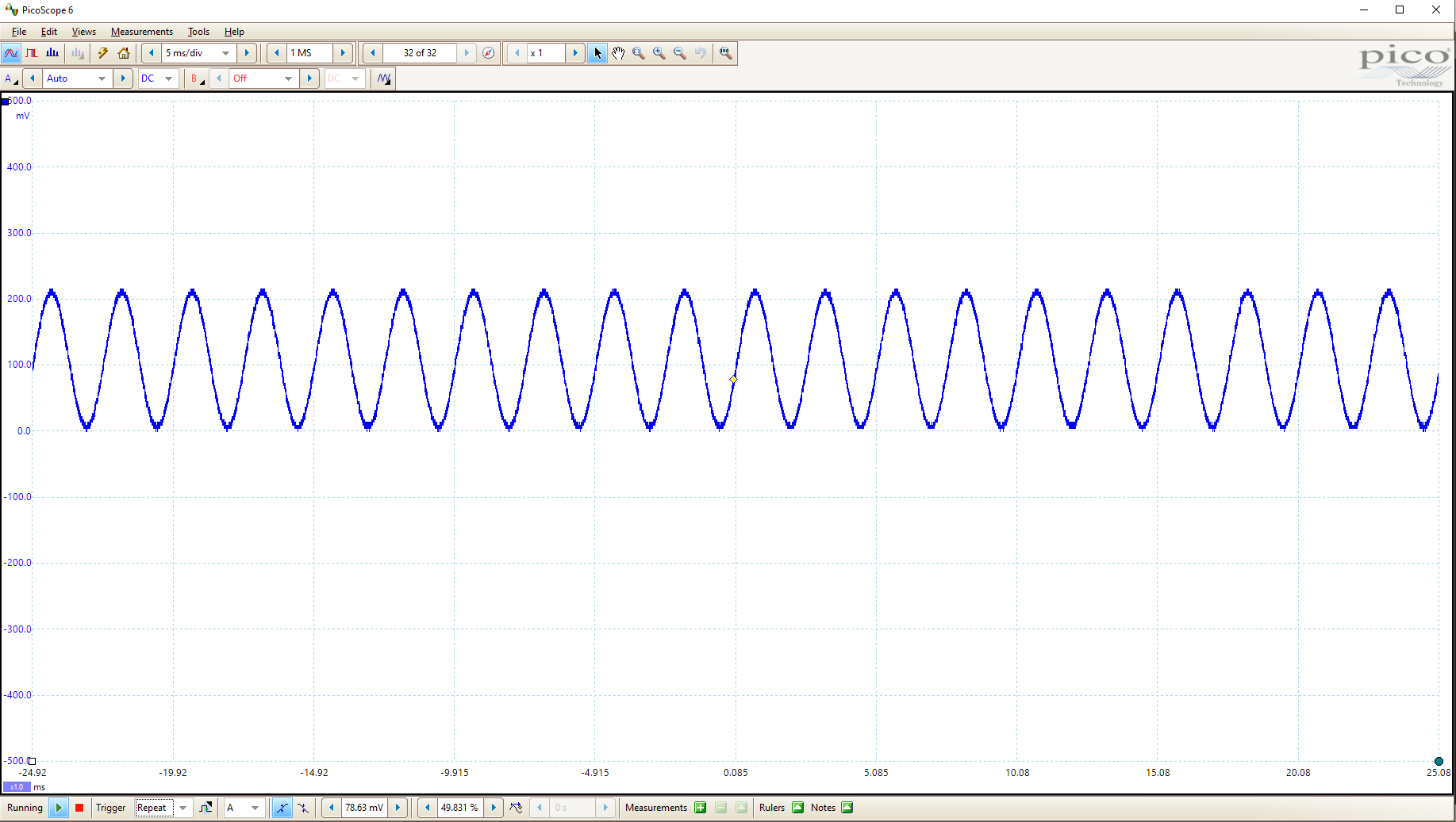
Note: Because of COVID-related shipping delays, it is possible that the PicoScopes oscilloscopes are not available for the first few weeks of the lab. Ask Hunter if there is a PicoScope installed at your lab bench. If there is not, you can use the sound card of your lab PC as an oscilloscope! This has certain limitations (we are limited to 100kSamples/sec, and we can only observe AC signals). Those limitations make the sound card less useful than a conventional oscilloscope for some application, but it is perfect for looking at sound coming from your DAC. Here is a guide for doing that:
Using Sound Card as an Oscilloscope
Only necessary if the PicoScope shipping is delayed! Though you may find this useful for Lab 1 anyway.
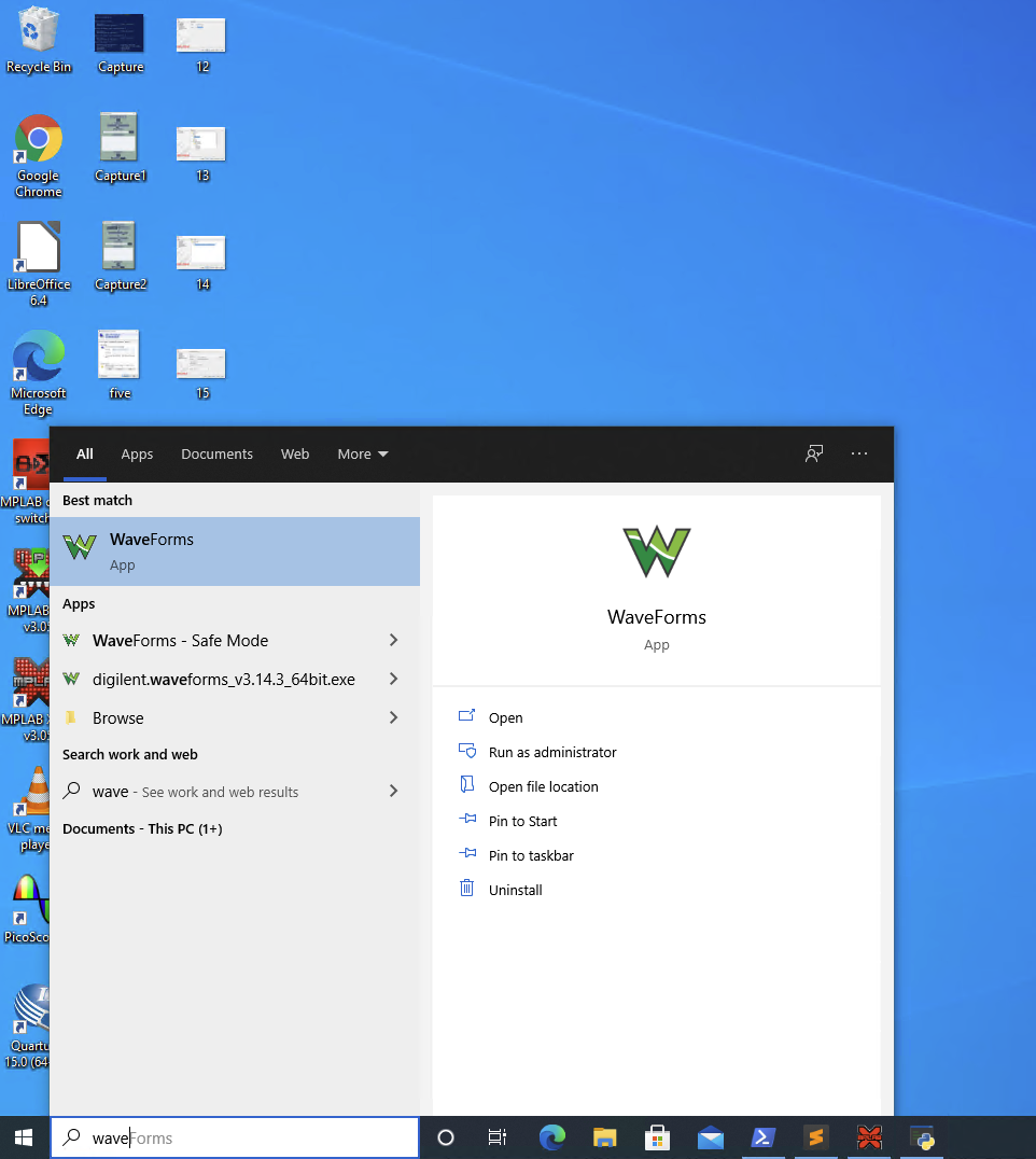
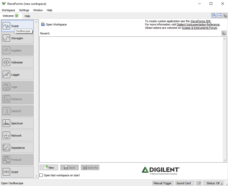
- Open the WaveForms application on your lab PC, as shown below:
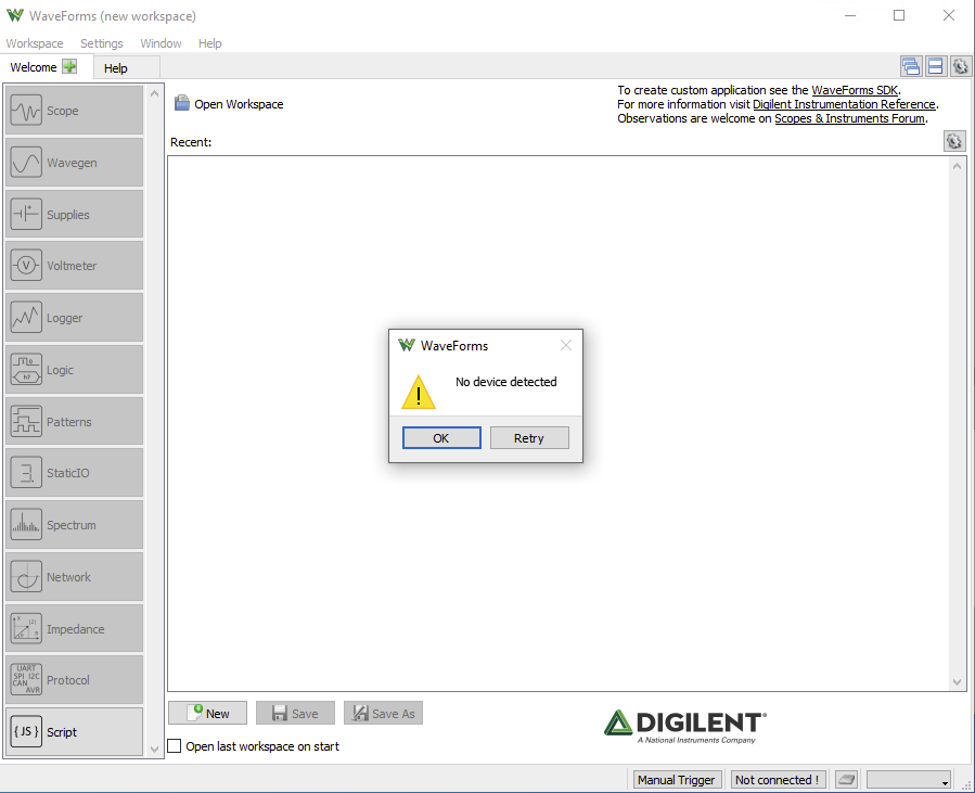
- A warning will pop-up stating that no device is detected. That's ok, just click "Ok":
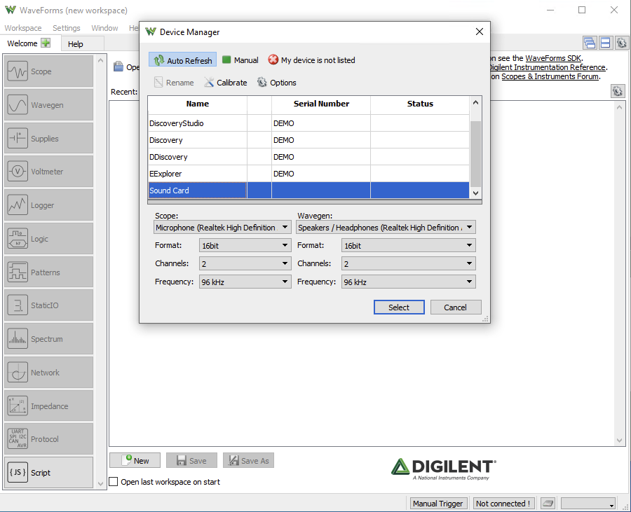
- Scroll to the bottom of the Device Manager list, and select Sound Card. Make sure that "Microphone (Realtek High Definition Audio)" is selected from the dropdown menu for scope. You can keep all other configurations as they are.
- Select the "Scope" button on the left side of the screen.
- Click "Run" and you will observe the waveform that is being input to the audio jack of your Lab PC, which is the high-passed output of the PIC32 DAC.
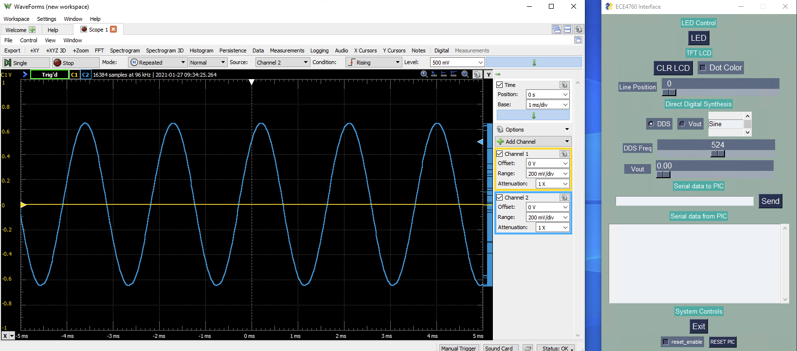
- Play with this! Note that there's a spectrogram option, that could be very useful for Lab 1. Change the DDS frequency in the Python interface and observe the change in the waveform. Note: if your waveform is clipped, you can turn down your microphone input volume in Sound Settings.
Listening to the example code through Zoom
As you can see on the Remote interface webpage, the output from DACA is put through a high-pass filter and into the microphone input jack of the lab PC. So, if you join the Zoom call from the lab PC and point Zoom to the microphone input, you will be able to hear the sound being generated by the PIC32 through Zoom.
- On the Lab PC, login to Canvas and join this Zoom meeting.
- You may need to wait for an instructor or TA to admit to you the meeting.
- In your Zoom sound settings, make certain that your Microphone is set to "Microphone (Realtek High Definition Audio).
- If Microphone (Realtek High Definition Audio) does not appear as an option, double-check your Remote Desktop audio settings to make sure that sound is being played on the remote PC).
- You should now be able to hear the tone being generated by the PIC through your headphones.
Running the associated Python code
- Download this Python code which is available on the Remote interfaces webpage under the subtitle "The python interface GUI running on the desktop."
- On the Lab PC, open device manager to determine the COM port to which the serial connection to the PIC32 is attached.
- Open the Python script and navigate to lines 34-36, which contain the following code:
# open microcontroller serial port
# For windows the device will be 'COMx'
ser = serial.Serial('/dev/ttyUSB0', 115200, timeout=0.001)
- Replace
'/dev/ttyUSB0'with the name of the COM port to which the PIC32 is attached. This will be of the formCOMx, wherexis the number of the port. - Make certain that the baud rate specified in the Python script is the same as the baud rate in
config.h.Should be 115200. - Open the Windows PowerShell application, and navigate to the directory which contains the python script which you've just edited.
- In the powershell, run
python .\pic_target_4a.py- NOTE: If this throws an error about PySimpleGUI, you may need to run
pip install PySimpleGUI - NOTE: If this throws an error about pyserial, you may need to run
pip install pyserial - NOTE: If this throws an error about the COM port, you may have edited the document to point to the wrong COM port. Double-check in Device Manager
- NOTE: If this throws an error about PySimpleGUI, you may need to run
- The window below will appear
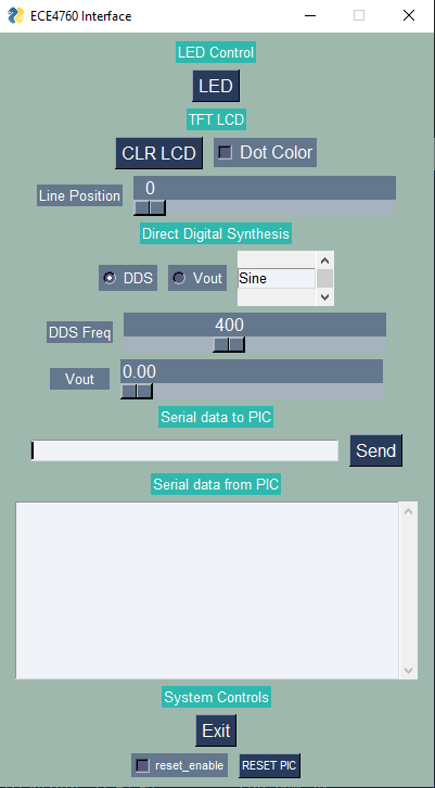
- This Python interface interacts with the C code that you've already loaded onto the PIC32. Open the Camera application so that you can see the board, and press the topmost LED button. You should see the LED illuminate when it is pressed. Toggling the "Dot Color" button will change the color of the circle on the TFT display, and the "Line Position" slider will move the line on the TFT display. If you change the DDS Freq. slider, you should hear the frequency of the produced tone change, and see the frequency change on the oscilloscope. You can also manipulate the shape of the wave being produced from a Sine wave to a square or triangle wave.