Cornell University ECE4760
Remote Access Interface
PIC32MX250F128B
Introduction
In spring 2021, ece4760 will be taught as a remote access lab course. This means that there will more emphasis on software and less on hardware. The microcontroller and development board will not change. However, interaction with the system will be via remote desktop running on the lab desk machines.Each station will have a development board, software oscilloscope,a camera pointed at the board and LCD display, an audio connection, and a serial connection from the desktop to the development board. The se;rial connection will support a Python script rinning on the desktop to simulate pushbuttons, toggle switches, potentiomenters, and a serial terminal. The Python script will talk to a protothreads thread on the PIC32 which decodes serial packets into high-level inputs. Each one of these interfaces will be described below.
The oscilloscope.
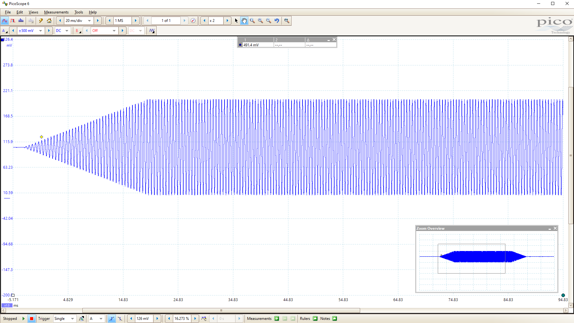
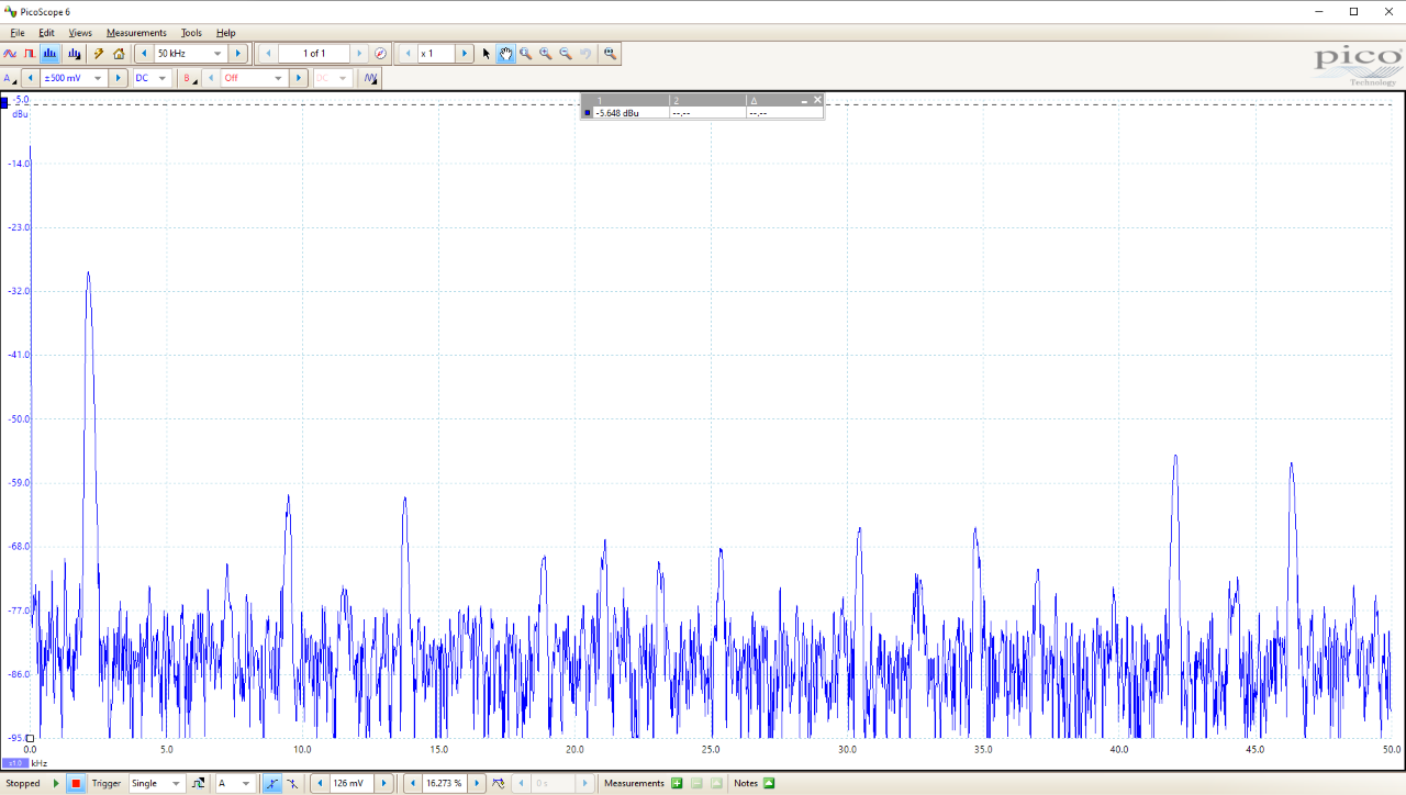
The oscilloscope we will use is the PicoScope 3203D PC Oscilloscope. The default scope connections will be to the two DAC channels driven from the development board. That connection may change depending on the lab exercise. Full access to voltage, time base and all the usual scope controls will be available through a software interface. Two display examples are below (click to expand).
The USB video camera
An image of the board, with a specrogram of music through a
zoom audio connection.
The video shows the screen-capture
with the Python interface on the left, the PIC32 video feed in the center, and
Hunter in his office on the right.
(click to expand)

A video and a still image shows the screen-captured performanceof Hunter
whistling into a zoom connection.
The Python interface on the left,
the PIC32 video feed in the center, and Hunter in his office on the right.
(click to expand)

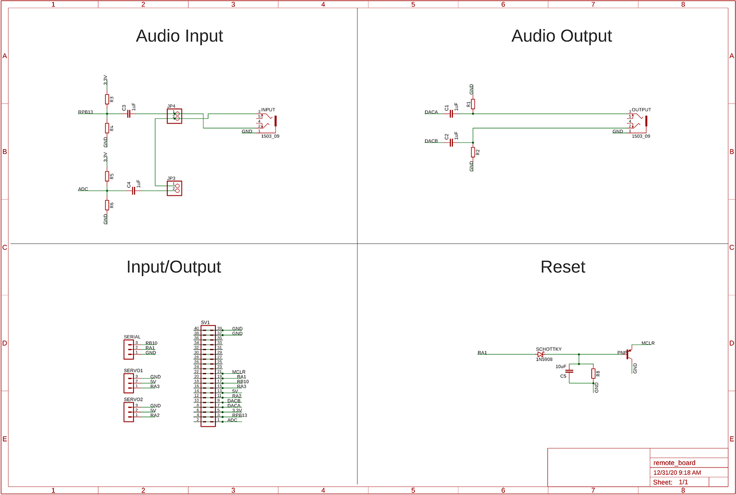
The Remote Learning hardware supporting the development board.

These connections will be made for you in the lab. The information here is given so that you can reason about the interfaces. For instance, because of the high pass filters, DC voltages do not appear on the PC input, but the scope probes will be DC or AC coupled from the scope user interface.
Audio input to the desktop computer will be connected to the stereo DAC output from the development board. The DAC output is high-pass filtered to remove DC bias (top schematic), since the DAC cannot produce a voltage less than zero and the PC expects a waveform of +1/-1 volt, symmetric around zero volts. DAC output to the scope is not filtered. There will two copies of this circuit, one for each channel.
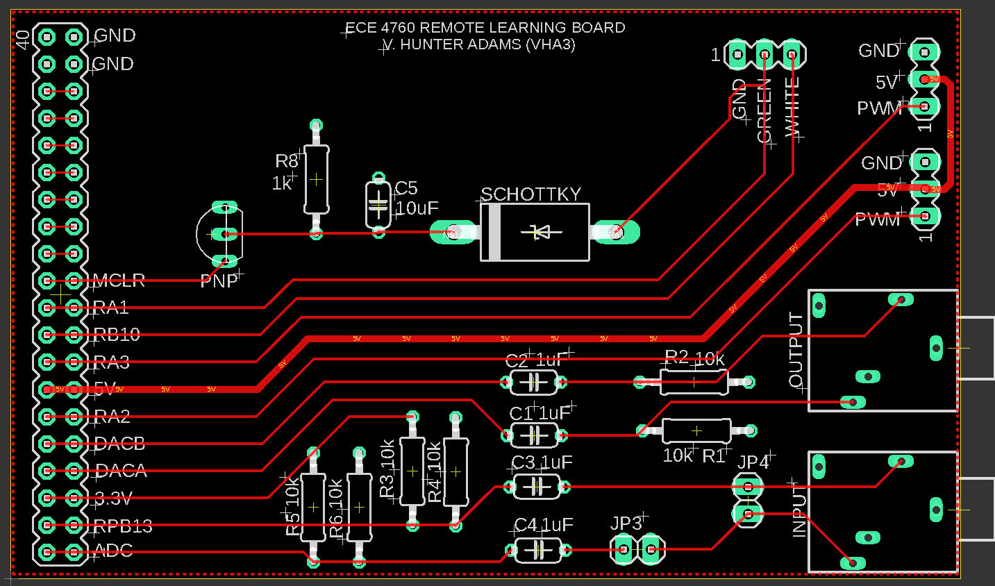
Audio output from the Desktop computer will be connected to one or two channels of the PIC32 ADC. Since the audio output is symmetric around zero volts, but the ADC requires a voltage between 0 and 3.3 volts, a highpass filter will be used to change the DC level of the signal to Vdd/2 (top-left schematic). There will two copies of this circuit, one for each channel. The first ADC channel is RB13, coresponding to ADC channel 11. The second channel (marked ADC) is not connected to any particularADC channel, unless a student group requests a specific connection.
The image below is the Remote Learning Board based on the schematic above.
You will be programming the
SECABB board, with i/o routed through this board.
The python interface GUI running on the desktop.
NOTE: The linked python scripts have file names of *.txt. You MUST rename them to *.py!
The user interface software consists of three pieces: A python script running on the lab PC, A serial link to the PIC32, a protothread which receives and decodes commands from the python script and converts the commands to state variables. Student-written threads can use the state variables for custom function, but, of course, an example code is given
. Connections for serial, reset, and communication will be made for you, although details are in the next section.
The first example requires these files: python script, PIC32 example code, modified protothreads, and config to include in demo code (ZIP). The serial baud rate specified in the prptothreads config file must match the serial baud rate specified in the python script. You may need to edit the python script to specify the correct Windows COM port.
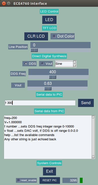
The visual interface
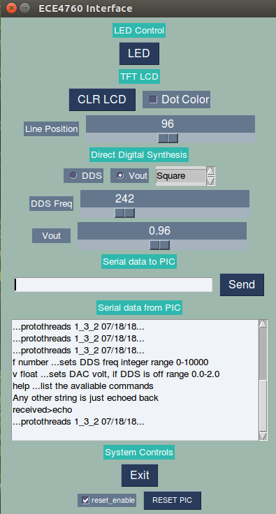
The python GUI is shown to the left (click-enlarge).
There are buttons, checkboxes (toggle switch), sliders, radio_buttons, list_box and text send/receive.
There are also controls to exit the interface and to force a reset on the PIC32.
The reset_PIC button is interlocked so that it only works of the reset_enable toggle is on.
Effect on PIC32
Each of the controls (except text input) send a 4-character descriptor to the PIC32.
The first character is the type (button, toggle, slider, radio, list).
The rest of the characters are determined by the type, but include a unique identifier (e.g. button number) and a value (e.g. button_pushed).
The text string send button just transmits the entire string.
The PIC may send arbitrary strings to be displayed
in the larger text area.
All transactions to/from the PIC32 are terminated by a '/r' character
----
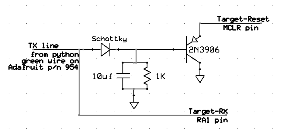
There cannot be any code on the PIC32 to implement the reset function!
The reset button forces an rs232 break condition transmission which is filtered and applied to the target MCLR pin.
(Reset circuit to perform a nonlinear filter on the serial line).
Extending the interface
All operations of the GUI were programmed using PySimpleGUI.There is an extensive online manual, and many examples. To add controls for your project you need to modify one control structure and follow a couple of rules. The scheme for generating a GUI are well explained, but I will put a summary here. Each item in the GUI (button, text field, etc) exists in rows with other items. For example, in the GUI shown above, the fourth row has the items CLR_LCD, and Dot_color. The first through third rows in the GUI each have just one item. In general, to add or modify the GUI you need to edit a list of lists in Python. For instance,
layout = [row_1-list, row_2_list, row_3_list]
will produce a GUI with three rows when used as input to the window builder.. To expand slightly, if we wanted two buttons preceeded by text in the first row, then a slider, then a row with two buttons, the list pseudocode might look like this.
layout = [ [text, button, button], [slider], [button, button] ]
The real code will call a method to build each different item, each with its own parameters. By default there are colors and size assigned, but you can change those for each different item in the GUI, if you want. After you have defined the window contents, you drop into an event loop which polls the controls for change and takes appropriate actions.
In the context we are using, the actions will be serial commands to the PIC32.
In my version of the interface, there will be a naming convention for each different item so that the appropriate serial commands can be automated. But first, the way that the GUI package identifies which item was manipulated by the user is by a key value. The key will be unique for each different item in the GUI. If you use these naming conventions, then any new controls you build will be recognized by my event loop and PIC32 code.
-- Each pushbutton will have a key value of the form key='pushbutNN', where NN are numeric 0 to 9. for example key='pushbut01'. example:
sg.RealtimeButton('LED', key='pushbut01', font='Helvetica 12')
-- Each toggle (checkbox) will have a key value of the form key='toggleNN' where NN are numeric.
sg.Checkbox('DDS', key='toggle02', font='Helvetica 12',enable_events=True, default=True)
-- Each slider will have a key value of the form key='sliderN' where N is a numeral 0 to 9.
sg.Slider(range=(0,200), default_value=0, size=(22,15), key='slider1',
orientation='horizontal', font=('Helvetica', 12),enable_events=True)
-- Each listbox (see example below)
will have a key value of the form key='listN' where N is a numeral 0 to 9.
The listbox mode must be sigle select.
sg.Listbox(values=['Sine', 'Square', 'Triangle'], key='list1', size=(10, 1),
select_mode='LISTBOX_SELECT_MODE_SINGLE', enable_events=True)]
-- Each radio button (see example below) will have a key value of the form key='radioM_N' where M is the one digit group number
and N is the one digit button number within the group. Two radio buttons in group radio1:
sg.Radio('DDS', "radio1", default=True, key='radio1_1', enable_events=True),
sg.Radio('Vout', "radio1", key='radio1_2', enable_events=True)
The PIC32 side of the interface
The PIC32 interface code is arranged as a thread which spends most of its time waiting for the interface user to generate an event.
When an event occurs, the thread generates a signal to one of several threads, and sets certain values shown in the table below. In the demo code linked above, there is also a thread for each diferent event type (e.g. button, or listbox). These event threads actually cause the PIC32 to do something useful (e.g. blink an LED) when an event occurs. An event thread should either block on the event signal, or poll it, if periodic execution is necessary.
When you write code for this class, you will probably not touch the interface thread, static PT_THREAD (protothread_serial(struct pt *pt)).
What you will do is to write handler threads for the events you need for the assignment, write interrupt handlers, and, of course, modify MAIN to set up the threads, interrupts, and other peripherials.
| Interface item |
Event |
Event signal set
(reset by event thread) |
Values set |
| push button |
press or release |
new_button |
button_id 00 to 99
button_value 0/1 |
| toggle switch (checkbox) |
check or uncheck |
new_toggle |
toggle_id 00 to 99
toggle_value 0/1 |
| slider |
move the slider |
new_slider |
slider_id 0 to 9
slider_value float
|
| listbox |
click an option |
new_list |
list_id 0 to 9
list_value 0 to 9 |
| radio button group |
change set button |
new_radio |
radio_group_id 0 to 9
radio_member_id 0 to 9 |
| string input |
no event
(until SEND button is pressed) |
new_string |
receive_string
up to 64 chararacters |
Adding interface events generated by the PIC.
Running the serial receive python code in a separate thread means that you can generate pySimpleGUI events based on serial input from the PIC. This is useful for numerical feedback to python, or for custom virtual controls. The feedback additions are two indicators in the lower right of the image. A text field which receives and displays time since reset on the PIC, and a simulated LED blinking at 1 Hz.
Python, PIC code, protothreads, config (ZIP)
Normal print commands in a user program just send a string(with '\r' terminator) to be displayed.
The PIC program signals that it is sending an interface event/command by prefixing a $ to the sent string.
When the serial thread in the the python script receives a string prefixed by $ it generates the event:
window.write_event_value('PIC_cmd', ser_str)
A normal string generates the event:
window.write_event_value('PIC_recv', ser_str)
The window read event loop in the MAIN thread must be modified to interpert the command.
Clearly the PIC and the python interface have to agree on the contents of the command string. (PIC send thread)
In this example there are two command types:
$01 time where time is an integer number of seconds.
and
$02b where b is a one-digit 1/0 binary.
You can define any other commands you want.
--
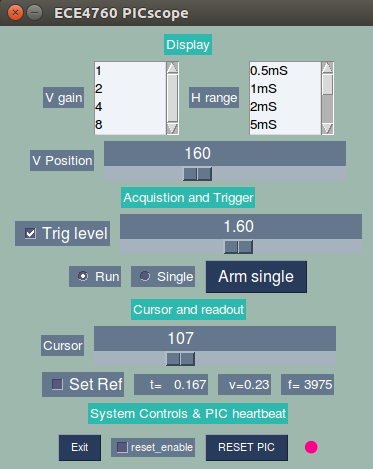
An example: PICscope oscilloscope
The scope samples one channel of the ADC (RB13)
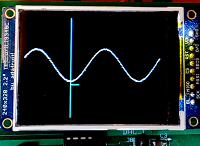
at up to 900,000 samples/sec. The trace is displayed on the TFT LCD and controlled by the python interface. The ZIP file contains the python script, C program, protothreads, and a config file. Unlike most of the other code, the config file is set to 60 MHz clock rate, with a factor of two divisor for the peripheral bus The reason for this is an obscure timing constraint on the ADC when the ADC is operated at maximum speed. DMA is used to move data from the ADC to memory. The rate is too high for interrupts. In the interface image the vertical gain is given in arbitrary scaling, but the voltages read by the cursor are in volts. The time scales are accurate. The vertical position slider is approximately in pixels (0 to 240). Trigger level is in volts. If the trigger level checkbox is empty, the the scope free-runs with no trigger. If the actual input voltage range does not overlap the set trigger level then the scope falls back to an untriggered mode. The Run/Single radio buttons determinewhether every trigger condition starts a trace, or whether the system waits for the Arm button to be pushed for the next trigger. The cursor slider moves the cyan vertical line left-right. The calibrated time, voltage, and an approximate frequency are displayed. If the Set Ref checkbox is on, then the cursor values that were current when the box was clicked become the reference, and the time, voltage, frequency fields read the difference between the reference and a new cursor position. The frequency is calculated as 1/(time difference). On the scope screen image, the vertical cyan line is the cursor and the small horizontal line is zero volts. For this version of the code, the voltage must be between 0 and 3.3 volts applied to ADC input RB13. I connected it through a 300 ohm resistor to partly protect the input if the voltage was outside that range.
(
See below for a version that allows inputs of -3 to +3 volts.)
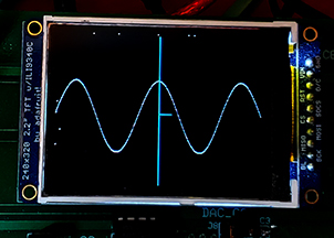
PICscope oscilloscope with ±3 input voltage, DC coupled.
This version requires an input conditioning circuit which takes the average of two voltages, then buffers the output with an opamp. Input impedance is high and coupling extends to DC. The 1 Meg resistors could be lowered somewhat, if noise is a problem, but should be matched, and at least 50 times the scope-input source impedance (for 2% accuracy). Actual accuracy depends on several factors and may need to be calibrated by setting Vdd in the python script. All controls work as above, but notice that the zero-line in the scope image is now in the middle of the waveform.
(python, C code, protothreads, config, and ZIP)
The serial connection to the desktop. (Students: ignore this section!)
On the PC side there will be a USB connection for serial communication between the running program and the PC, which will be running PuTTY. Set up PuTTY for baud-rate set in config_1_2_2.h (or after), no parity, 1 stop-bit, no flow-control. In the PuTTY config window, choose serial connection, then click serial in the left hand panel and set the parameters. Connect PuTTY to whatever serial port the USB connection configures. Use Control Panel...System...Hardware Tab...Device Manager Button...+Ports to find out which serial port is connected to the USB connection. If the PC does not autoload the required driver, then the COM port will not be attached or listed. Look for Prolific USB-to-serial Comm Port. If this happens then you will need to manually download the driver from Adafruit. You probably want the SiLabs Chipset driver CP210x, but check the device manager. It may be the Prolific Chipset PL2303. Mac OS versions are here.
UART to USB Adafruit serial cable:
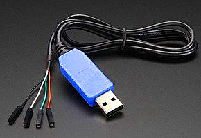
The blue serial-USB connection is a USB cable with embedded USB/serial bridge chip with 3.3 volt logic levels.
-- Use wires to connect the the three signals below.
-- Do NOT connect USB Vcc (red wire) to anything,
unless you need 5 volt power for a circuit not associated with the MCU.
-- Connect UART receive pin (U2RX) to the green wire (default to RA1 on big board)
-- Connect UART transmit pin (U2TX) to white wire (default to RB10 on big board)
-- Connect MCU ground to black wire
Standard Serial library for the UART
The standard serial library for GCC is <stdio.h>. All of the standard library routines are blocking, so don't use them in a threaded environment, unless speed of execution is more important than multasking. Instead use the ProtoThreads support explained below, and on the protothreads page. But for completeness, the standard i/o libary serial routines are outlined here.
In included in the library are routines to:
- Convert variables from internal format to a printable string, and optionally send them to the UART.
Works for strings, chars, ints, floats. Limited support for fixed point.
-- sprintf converts multiple internal binary formats to a serial-format string in memory.
This routine is fast and can be used with Protothreads.
-- printf converts internal format to a string, and sends the string to the UART.
Do not use printf IF you are using Protothreads and you need fast multitasking!
At the fastest baud rate you can use 115200 bits/sec, each character set ties up the processor for 100 microseconds,
or 4000 cycles! The Protothreads routines swap to a different task during each character transmission.
Context switch to a new task is about 20 cycles.
- Convert a string into internal format. The string may come from the UART.
-- sscanf
converts a serial string in memory into internal binary format.
This routine is fast and can be used with Protothreads
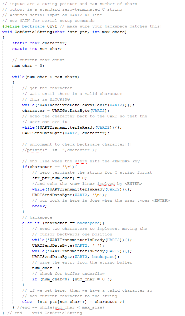
-- My GetSerialString routine builds a string in memory from the UART.
But remember that GetSerialString is built in to Protothreads where it is called PT_GetSerialBuffer.
I wrote this routine as the first step in converting the serial input to Protothreads.
I included it here to show how the UART works.
Do not use GetSerialString IF you are using Protothreads and you need fast multitasking!
GetSerialString will tie up the processor for as long as the very slow human takes to type a line!
Protothreads swaps out the thread to let some other thread execute while waiting for the human.
-- scanf
SHOULD convert a serial string from the UART into internal format, but it does not work on this compiler!
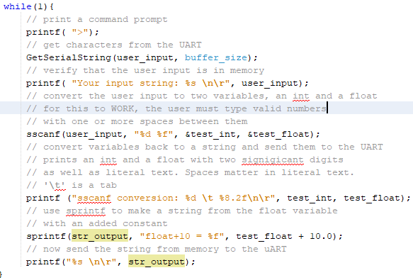
The workaround is to use GetSerialString, followed by sscanf, as shown in context in the example Code.
But remember that GetSerialString is built in to Protothreads where it is called PT_GetSerialBuffer.
ProtoThreads Serial support
ProtoThreads 1_3_2 has support for using the UART communication to a PC serial terminal. The ProtoThreads 1_3_2 header assigns U2RX to RA1 and U2TX to RB10. The BAUD rate is set in config_1_3_2.h. The header also defines non-blocking transmit and receive routines for the UART. These routines are non-blocking DMA/polled transmit routines and non-blocking polled receive routines.
The UART serial interface is inherently slow, so for good multitasking, the string transmit and receive functions need to be able to yield to the scheduler. The transmit routines, PutSerialBuffer and PT_DMA_PutSerialBuffer can yield on a per-character basis or on a full string if the DMA transport routine is used. For all the details see the ProtoThreads page. An example code shows how to use the routines below. There are more examples on the Protoboard page.
PutSerialBuffer -- A thread which is spawned to send a string input from UART2. String to be sent is in char PT_send_buffer[max_chars]. If more than one thread can spawn this thread, then there must be semaphore protection. Control returns to the scheduler after every character is loaded to be sent. This thread returns to the parent thread after it sends the entire string. To use this, config_1_x_x.h must contain #define use_uart_serial- PT_DMA_PutSerialBuffer -- A thread which is spawned to send a string input from UART2. String to be sent is in
char PT_send_buffer[max_chars]. If more than one thread can spawn this thread, then there must be semaphore protection. Control returns to the scheduler immediately. This thread returns to the parent thread after it sends the entire string. To use this, config_1_x_x.h must contain #define use_uart_serial
There are two different receive routines. One assumes that a human is typing on a terminal, the other assumes that a machine (e.g. another PIC32, an Aduino, or GPS module) is sending information over the UART. A human expects to be able to see what they are typing, be able to erase characters, and always terminates a transaction with the <ENTER> key. None of those expectations are true for a machine connected to the serial input.
- PT_GetSerialBuffer -- A thread which is spawned to get nonblocking string input from UART2. This function assumes that a human is typing at a terminal and thus supports backspace, termination by enter key and echos characters! String is returned in char PT_term_buffer[max_chars]. If more than one thread can spawn this thread, then there must be semaphore protection. Control returns to the scheduler after every character is received. This thread returns to the parent thread after it receives an <enter>. To use this, config_1_x_x.h must contain #define use_uart_serial
PT_GetMachineBuffer -- A thread which is spawned to get nonblocking string input from UART2. This function assumes that a machine is sending data and thus does not assume any particular termination condition and does not support backspace, or echo characters. You can specify termination method. A terminator character (PT_terminate_char), or a character count (PT_terminate_count), or a timeout (PT_terminate_time). A zero for any of the three disables that termination condition. String is returned in char PT_term_buffer[max_chars]. No string is returned if there is a timeout. If more than one thread can spawn this thread, then there must be semaphore protection. This thread returns to the parent thread after it receives an termination condition. To use this, config_1_x_x.h must contain #define use_uart_serial
The 1_3_2 version uses DMA channel zero transfer for higher speed.
Copyright Cornell University
February 15, 2021
