Introduction
I created a hardware implementation of a falling sand game, inspired by the Java-coded Pyro Sand Game, which is not actually a "game" in the strictest sense, as it lacks an objective, but is more accurately a 2D particle simulator that satisfactorily models certain dynamics of falling sand.
I noticed while playing the Java version of the game that my laptop would require very much processing power, its fan would become loud, and the frame rate of the game would slow down when too many particles were on-screen. Therefore, I thought the application could benefit from the FPGA on an Altera DE2 board, which can run the game at a constant frame rate with dedicated computational power that is not shared with an operating system or other applications, as would be the case on a laptop running the Java version. Utilizing the FPGA's registers also allows parallelization of certain memory and variable transactions that would likely be serial in a software implementation, and this parallelization saves a significant number of clock cycles when considering the number of particles whose states need to be updated during each frame.
High Level Design
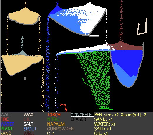
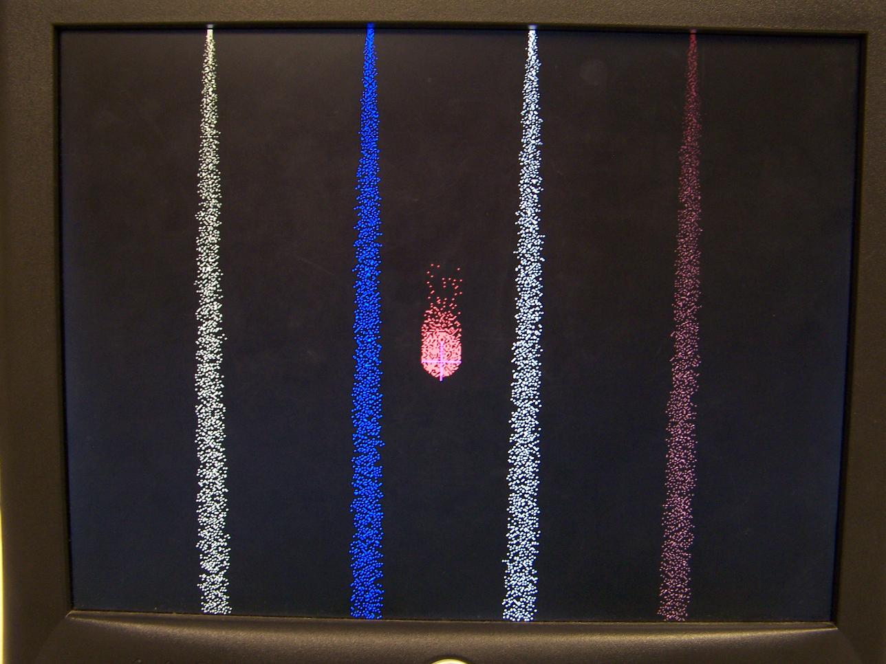
The Pyro Sand Game is itself only one of many variations of similar falling sand games. It includes 17 different drawable particle types, most of which can be categorized as either an immobile wall-like particle (such as wall, plant, or wax) that ignores both gravity and other forces, or a mobile sand-like particle (such as sand, water, or salt) that does experience a gravity force and can be pushed by other particles. These particle types can be seen in Figure 2, a screenshot of the Pyro Sand Game, in which the mobile particles tend to form streams of spaced individual pixels. Exceptions to these categorizations include fire, which models fire (although this can be thought of as a temporary immobile particle), and eraser, which erases all other particles and can be thought of as drawing a blank-space particle. Different types of particles have different interactions with one another; for example, fire propagates quickly through oil. Many such interactions involve particles that are touching each other, either laterally or diagonally, and they can be considered proximity transforms. There are four faucets at the top of the screen that release a steady stream of sand, water, salt, and oil particles into the simulation. Particles fall off the bottom of the screen but are bounded by the left and right edges. The user may also select a particle type and draw it anywhere on the screen, and he or she may customize the size of the cursor and faucets.
From observing the Java version, I noted the following behaviors of mobile particles. First, they tend to fall when there is a blank space below them, but on rare occasions they do not, which is most noticeable when there are two particles adjacent to one another either horizontally or vertically during one frame but then not during the next. Second, they tend to push each other sideways, which is most noticeable when they have landed on a wall and have begun to form a pile, which then spills to the left or right. The pushing direction is biased to one direction over the other, with the bias alternating on every other row, but it is possible in either direction regardless of row. Third, particles like sand and concrete can fall into water, but they fall less quickly than in blank space, and they tend to form stable triangular piles that do not shift out of place. Water can fall into oil in a similar manner, but particles that fall into water do not fall into oil.
I decided to model the particles as a cellular automaton (CA) in which each pixel in the entire 640 by 480 screen is a cell. It would be difficult to try to compute a screen update or row update in a single cycle because there are dependencies of some particle movements on earlier particle movements within the same frame for example, if mobile particles a row down can fall because there is blank space beneath them, then mobile particles in the current row will be able to fall as well. Detecting this dependency in one clock cycle would require a long propagation of fall check bits from the bottom row to the top, and ignoring this dynamic would create a staggered fall in which particles naturally separate into rows separated by a pixel height of blank space. A similar case exists for shifting movement within a row of a mobile particle heap. As a result, pixel updates must happen sequentially, progressing from the bottom of the frame to the top to resolve the falling dependency, and alternately progressing from left to right and right to left to resolve the shift dependency within a row and to mimic the Java implementation's alternating shift direction bias. The next state of a pixel is then dependent on the previous states of its eight nearest neighbors and the updated states of the neighbors below and to the side that have already moved during the current frame.
The decision to update the state of each pixel via a CA rule means that any sense of state beyond a single-value pixel type is omitted. Particles cannot have a concept of velocity or direction unless special particle types are created to encode this information; for example, one could create a pixel value that represents a sand particle moving left or another value that represents a sand particle falling down. I chose not to implement these concepts because of memory constraints. Because the entire screen must be drawn to a VGA screen, the pixel states must be stored in a memory structure that is both fast to access and large enough to store the entire CA state (640 by 480 visible screen). The options available on the DE2 board that are guaranteed to meet the timing constraint are the 4MB SRAM and the 472.5KB M4K blocks. The memory writes by the CA must also be synchronized with the VGA control structure so that the frame currently being drawn to the screen is not updated in mid-frame. Because the CA and VGA iterate over the rows of pixels in opposite directions, there would be no way to guarantee this timing if they accessed the same memory region unless the CA updated the screen during the time when the VGA is not requesting visible row data. The VGA signal consists of 525 rows 480 visible and 45 invisible each of which consists of 800 pixels, or 25.2MHz clock ticks 640 visible and 160 invisible. In total, the CA would have 36000 25.2MHz clock ticks, or 72000 50.4MHz clock ticks, to update its state during the invisible lines of the VGA signal. This limit is too low to update the entire screen, which contains 307200 pixels. Therefore, I split memory into a low half and high half and use each half to store either the previous frame, which is being read by the VGA controller and drawn to the screen, or the next frame, which is being calculated in parallel with the drawing process. The two regions of memory alternate each frame, so that the VGA controller will only read from a region of memory after it has been entirely updated by the CA state machine during the previous frame. This leaves 2MB SRAM or 236.25KB M4K blocks to store an entire 307200-pixel screen. Using SRAM is then the only viable option, allowing up to four bits of state per pixel, whereas the M4K blocks would not be able to fit even one bit per pixel. This limits each pixel state to sixteen possible values, and in order to implement as many of the pixel types found in the Pyro Sand Game as possible, I chose to omit allocating any states to velocity information.
Most pixel types from the Pyro Sand Game were implemented, with the ironic exception of the ones that merit the title "Pyro" (which is why this project itself is merely titled "Falling Sand Game"). That is, the nitro, napalm, gunpowder, and C-4 types were not implemented. These particle types would have been difficult to implement anyways, because when they react with fire, they have an area of impact that is outside the 3 by 3 neighborhood used to calculate the next state of a pixel. It would have been possible to model their behavior using many states that correspond to a diminishing radius effect, but it would have been costly given the limited number of total states. Also omitted was the well type, which I found uninteresting because of its similarities to the spout type but without the benefit of plant interactions, as discussed below. The sixteen pixel types that were implemented are listed in the following table.
| Color | Particle Name | Description |
| Blank | A value to represent an empty space, or open air. | |
|
Fire 3 Fire 2 Fire 1 Fire 0 |
Several states to implement fire simulation. Fire 1 and fire 0 simulate the rising behavior of fire. A fire 0 particle will always become blank during the next frame, but it will randomly inject a fire 1 into a blank space above it. Fire 1 will become fire 0 before extinguishing into blank. As a result, a column of fire may rise forever, but it has a height probability distribution that decays exponentially. Oil located next to something hot (fire 1, fire 0, or torch) will become fire 1, resulting in a quickly propagating fire. The states fire 2 and fire 3 exist for slower-burning objects. Plants become fire 2, which becomes fire 1, and wax becomes fire 3, which only becomes fire 2 with low per-frame probability. Fire 3 and fire 2 are themselves not hot. | |
| Torch | An immobile infinite source of fire. It randomly injects fire 1 into non-wall pixels to the side or above. | |
| Water | A mobile particle that sinks in oil and becomes plant when next to plant to simulate a plant that grows in water. | |
| Sand | A mobile particle that sinks in water. | |
| Oil | A mobile particle that becomes fire 1 when next to something hot. | |
| Salt | A mobile particle that becomes salt water when next to water. | |
| Concrete | A mobile particle that sinks in water and probabilistically becomes wall when touching something solid (sand, salt, wall, wax, or plant). | |
| Salt Water | A mobile particle that sinks in water. | |
| Wall | An immobile particle. | |
| Plant | An immobile particle that grows in water and becomes fire 2 when next to something hot. | |
| Wax | An immobile particle that becomes fire 3 when next to something hot. | |
| Spout | An immobile particle that randomly injects water into surrounding blank spaces. |
The high-level logical structure of the design can be inferred from the above description and Figure 3 in the Hardware Design section, showing the important hardware modules. In summary, there are two frames of the screen stored in SRAM the previous frame and the next frame. While the VGA controller requests pixel data of the previous frame from the top of the screen down, a CA state machine also reads the previous frame from the bottom of the screen up and derives the next frame. User input logic receives commands from a PS/2 keyboard or the switches and pushbuttons on the DE2 board, which allows the user to move a drawing cursor, change the drawn particle type, and modify the size of the cursor and faucets. The user may also issue certain system commands, including a pause/resume command that holds the screen still but allows further drawing, a reset screen command that instantly sets all pixels to the drawn particle type, and a troll command, which begins a 2-second animation that covers the entire screen. Because the user must be aware of where the cursor is, and because the animation is drawn over the standard screen, the system may select to retrieve the VGA pixel request's value from either a screen frame stored in SRAM, a static purple color to indicate the cursor, or from a special memory structure that stores pictures of the animation.
In order to match the high demand rate of one screen iteration per 60Hz frame, the CA state machine must be implemented in hardware to control cycle-by-cycle memory management. A software implementation would not be able to maintain the 60Hz rate on this 50MHz FPGA system. It would require a faster processor that could perform more work between frames. Because the VGA and CA controllers are the largest portion of this project, and the remaining modules are small state machines, the rest of the system is implemented in hardware.
Hardware Design
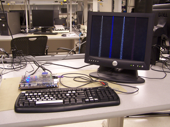
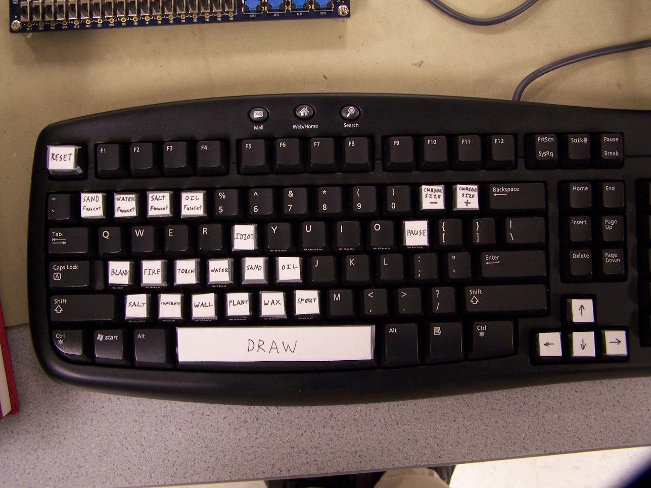
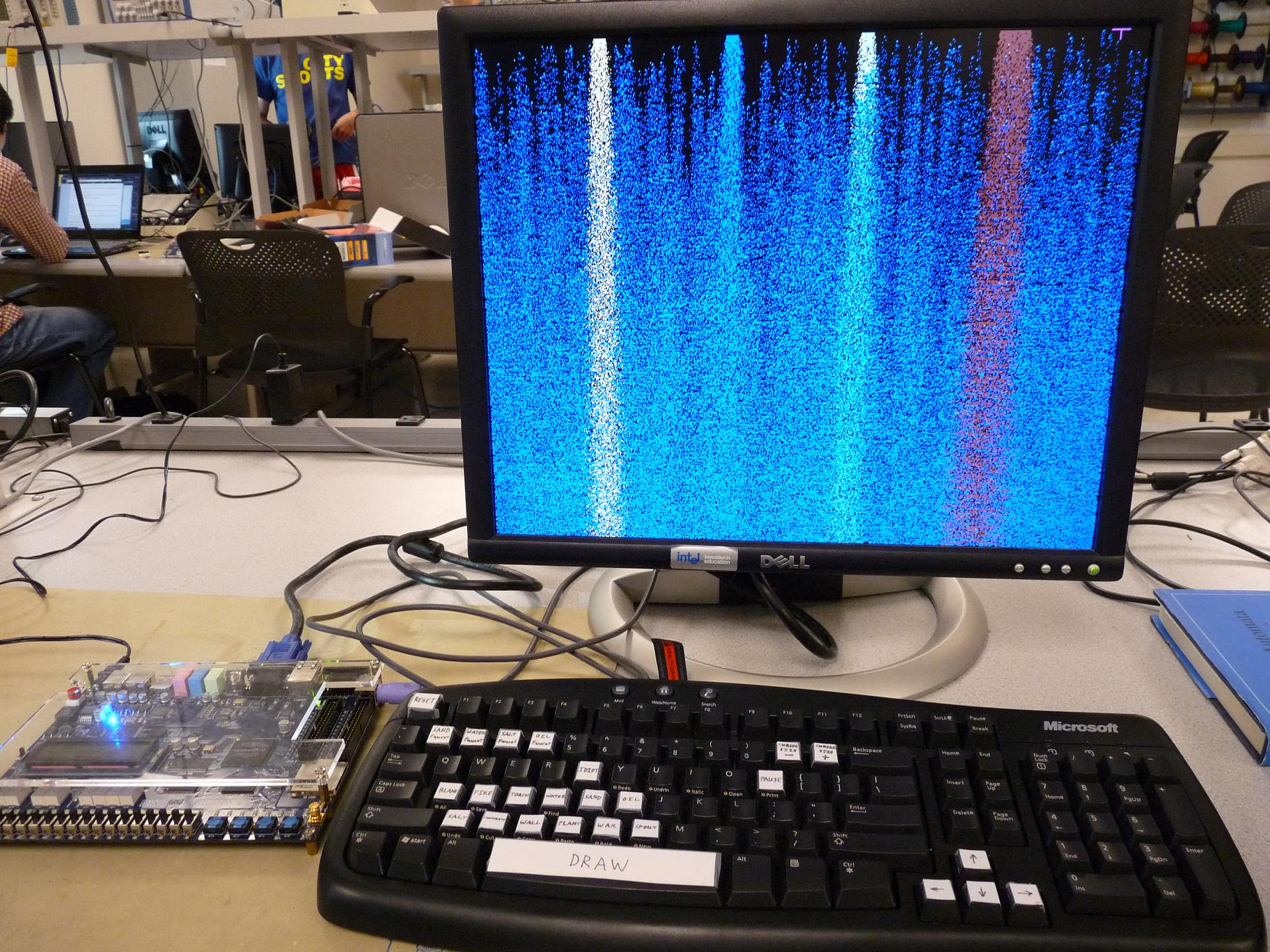
The physical design was shown in Figure 1 in the Introduction, and it consists of an Altera DE2 board, an external VGA monitor, and a novel PS/2 keyboard with custom labeled keys (shown in Appendix A). The rest of the design was implemented as hardward downloaded to the FPGA. All Verilog code can be found in Appendix C.
Figure 3 shows the skeleton structure of the hardware design. The DE2_TOP module merely connects the various inputs, outputs, and submodules in the design.
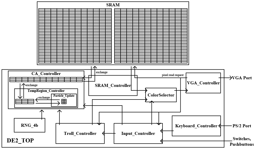
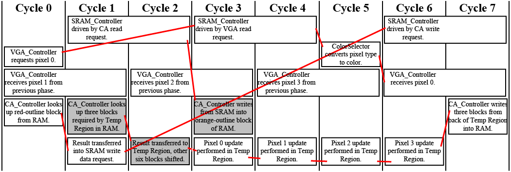
The entire system is clocked at 50.4MHz, with the exception of the VGA output clock, fed to the external VGA monitor, which is clocked at 25.2MHz. Because each pixel is stored as 4 bits in SRAM, and each SRAM word is 16 bits, the SRAM_Controller only needs to send one read to the SRAM once per 8 clock cycles at 50.4MHz, and the resulting data will be able to feed the VGA pixel request for four pixels, or four 25.2MHz cycles. Therefore, I define a "phase" as 8 clock cycles and synchronize system behavior during each phase. The VGA_Controller, which requests pixel colors several cycles in advance and outputs the colors to the VGA monitor, is also in charge of maintaining a SystemState register, which counts which clock cycle within a phase the system is currently in, as well as a NewFrame signal, which is asserted after drawing the last visible pixel of each frame, so that the rest of the design can be synchronized to swap the two frames in SRAM and begin overwriting the frame that was just drawn at that time. Cycle 0 within a phase is aligned such that it corresponds to the first pixel in each row, or more generally, the SystemState is always equal to X % 8 where % is the modulus operator and X is the horizontal position of the pixel whose color is being requested during that cycle. The pixel address specified during cycle 0 corresponds to the pixel whose color will be required by the VGA_Controller during cycles 6 and 7. During cycles 3 and 4, the SRAM_Controller drives the SRAM address so that the requested pixel's particle type is ready by cycle 5, and the color can be looked up in a ROM in the ColorSelector during that cycle so that the color is ready by cycle 6.
In order to match the VGA_Controller's rate while maintaining a well-synchronized timing scheme, the CA_Controller must also process four pixels per phase. However, each of the four pixels requires the states of its eight neighbors to determine its next state and may modify the states of those neighbors through their interactions (for example, sand falling in water actually swaps the higher sand particle with the lower water particle). There are not enough clock cycles per phase for the CA_Controller to read and write all of those pixels in one phase, and so it must instead store a temporary copy of old values and only store and load one 4-pixel block to and from SRAM per phase. The scheme that is used is depicted in Figure 4. The black grid represents an example 24 by 6 pixel screen, separated into a matrix of 6 by 6 4-pixel blocks. The center blue-outline block corresponds to the block whose four pixels are the primary ones being evaluated during this phase, and the other blue-outline blocks are those in which at least one of the primary pixels has a neighboring pixel that is required in the state update logic. In the CA_Controller are three RAM blocks (mapped as M4K blocks), each capable of storing an entire row of pixel data. In Figure 4, the shaded black-outline boxes (regardless of shading color) are the ones whose pixel values are currently stored in those three RAM blocks. At the beginning of a new frame calculation, the block of primary interest is set two blocks down and right off-screen. Then that block iterates across the screen from bottom to top, scanning each even row from left and right and each odd row from right to left. The orange-outline block represents a lookahead block whose values are loaded from SRAM to RAM during that phase, and the red-outline block represents a writeback block whose values are written from RAM to SRAM during each phase. Blocks that are shaded yellow are those that have been loaded from SRAM to RAM but have not been processed, blocks that are shaded blue are those that have already been updated as the block of primary interest, and blocks that are shaded red are those in RAM that have already been written back to SRAM after modification. Once the block of primary interest reaches two blocks up and left off-screen, the iteration is done for that frame. It can be seen that with this scheme, all calculations for the block of primary interest involve blocks in RAM that have already been loaded from SRAM, writebacks occur after all possible modification of the corresponding blocks, and by the end of the iteration, all blocks have been loaded, modified, and written back. The CA_Controller handles the timing such that its read address provided to SRAM is equal to the equivalent location of the orange-outline block during each phase, the write address and data provided to SRAM are equal to the equivalents of the red-outline block, and the write enable signal sent to SRAM is only high when the red-outline block is actually on-screen. The SRAM_Controller handles the read request during cycles 1 and 2 of each phase and handles the write request during cycles 6 and 7. As a result, the CA_Controller must write to its RAM during cycle 3 and read from its RAM prior to cycle 6 (chosen as cycle 0).
The problem with the RAM storage of the three rows is that to update the state of any one pixel requires the simultaneous read of all nine pixels within the immediate 3 by 3 vicinity, which may require simultaneous reads of up to 6 blocks from those rows (two per row, at the horizontal boundaries between blocks). To solve this problem, another layer of memory called the Temp Region exists, and similar to how the three RAM rows were temporary buffers for SRAM, the Temp Region is a temporary buffer for the RAM rows. It is a 12 by 3 pixel region, or 3 by 3 blocks, whose contents always correspond to the blue-outline blocks in Figure 4; collectively, the CA_Controller and TempRegion_Controller modules ensure that this constraint is met. During each phase, in cycle 2, the three forward-most blue-outline blocks (relative to their direction of movement, either left or right) are written from RAM to the Temp Region, and the other six blue-outline blocks were already in the TempRegion the previous phase, so they are merely shifted over. Then during each cycle from 3 to 6, nine pixels are combinationally muxed into the Particle_Update module from the Temp Region, and their next values are combinationally computed and update the Temp Region at the next clock tick. Finally, in cycle 7, the three back-most blue-outline blocks are written from the Temp Region to RAM. In summary, Figure 5 shows the precise per-cycle flow of important data during each phase. Black boxes represent calculations or events that occur within that cycle or upon the next clock tick. Red lines show dependencies in time. It can be seen that neither SRAM nor the RAM rows in CA_Controller are driven by more than one request at a time, and all data dependencies are resolved. The gray blocks represent writes into regions of memory that are parallel to the RAM and Temp Region, called OLD and Old Region. It can be seen in Figure 4 that sometimes the block of primary interest is updated based on the values in blocks that are already shaded blue, meaning that they have already been modified during this frame. As was mentioned in the High Level Design section, this strategy allows for proper falling and shifting behavior. However, there are other particle behaviors that require the unmodified states from the previous frame, such as the growth of plant particles into water, which should only happen at a rate of one pixel per frame. Therefore, OLD and Old Region contain the values of the equivalent pixel regions of RAM and Temp Region without modifications during this frame. OLD loads from SRAM at the same time RAM does, Old Region loads from OLD at the same time Temp Region loads from RAM, and nine pixels from Old Region are muxed as inputs into Particle_Update.
As already mentioned, Particle_Update combinationally determines the next state of a 3 by 3 pixel neighborhood based on the previous and modified states of those nine pixels, with a special focus on determining the next value of the center pixel. Note that when a downward or upward neighbor of the center pixel is off-screen, the value for a blank particle is substituted in by the TempRegion_Controller, but when a left or right neighbor is off-screen, the value for a wall particle is substituted instead. Also note that the next state of the pixels may be affected by random numbers, provided by the RNG_4b module that uses four Linear Feedback Shift Registers with different initial seeds to produce a four-bit random number each cycle, which can then be used to create events with probabilities in increments of 1/16. The states may also be influenced by user input, provided by the Input_Controller and Troll_Controller. In order of precedence, the following checks occurs. First, if the user issued a reset command, all pixels become the current particle type of the user's cursor. Second, if the user is currently drawing with the cursor over the pixel whose state is being calculated, that pixel is drawn. Third, if the system is paused, the particles stay still. Fourth, if the particle is directly beneath a faucet, the faucet will pour its corresponding particle type into the pixel. Fifth, if the troll animation is running, the pixel may be randomly flamed. Sixth, if there are any proximity transforms (that is, transformations invoked by neighboring pixels, such as water turning into plant or oil turning into fire 1), then it takes precedence over particle movement. Finally, if none of the prior occurred, the directions in which the particle can fall or shift are determined, and the particle randomly selects one, with falls taking precedence over shifts. If no fall or shift is possible, the particle must stay still.
With the CA, SRAM, and VGA logic aside, the remaining modules are not particularly complicated. The Keyboard_Controller converts the PS/2 input bit stream into 8-bit event codes for each observed make or break code (key press or release). The inputs from the keyboard and on-board switches and pushbuttons are fed into the Input_Controller, which can select from either method of input and modifies system variables and issues commands to the CA. Commands are synchronized on the frame level so that a reset, pause, or draw signal will apply to all or no pixels within a single frame, instead of only some. The modifiable system variables are the cursor size, faucet widths, and cursor particle type. The commands issued include a reset command, a pause command, a draw command, and a troll command. The Troll_Controller handles the troll animation after a troll command. The animation lasts 120 frames at 60Hz, or 2 seconds, during which four 160 by 120 pixel pictures are loaded cyclically from an M4K ROM (although they are stretched to fill the entire 640 by 480 screen). The picture changes every 10 frames, and at each of those picture transitions, every pixel on the screen has a 1/16 chance of being flamed and thereby becoming fire 3. The ColorSelector must answer the VGA request for each pixel by choosing to return either the color loaded from SRAM, the purple color of the user's cursor, or the corresponding troll animation pixel color, and it ensures that all of those choices are buffered until the appropriate time, six cycles after the original pixel request.
Code Considerations
The VGA_Controller and PS2_ScanCodeReader modules were at one point in the past derived from examples by John Loomis. Both have undergone changes by ECE 5760 staff and students, and the VGA_Controller in particular has undergone extensive modifications to reach its current state.
The Verilog implementation in the Particle_Update module was based very much on observations of the behavior of the Pyro Sand Game, but not its source code.
A PLL megafunction, the VGA_PLL module, was created using the Altera Megafunction Wizard.
Testing and Debugging
This project was built incrementally, starting with the VGA driving logic that drew a predetermined pattern to the screen. At first, there were problems with the timing of the VGA_Controller that would result in the end columns of the image being omitted, duplicated, or shifted vertically. Some of these effects were caused by off-by-one errors in the timing or pixel address specification, but others occurred when the Verilog code was logically correct. In the end, the module required a modification to request pixel data for 641 pixels per row, numbered -1 to 639, even when the data for the theoretical pixel -1 was neither required nor reported to the VGA monitor, in order to avoid what was believed to be a capacitance issue when receiving the value of the leftmost column of pixels.
Afterwards, the SRAM arbitration logic was implemented, and a simple screen iterator was created in the CA_Controller module to draw another predetermined pattern to the screen, with particle type based on the position of the pixel. This iterator was then fleshed out into the TempRegion_Controller and Particle_Update modules, while still only drawing predetermined patterns. There were no problems with this step.
Next, the dynamics of mobile particles were introduced into Particle_Update. First, the particles were allowed to fall vertically from a predetermined reset pattern. This produced columns of pixels that moved downward together on the screen. Next, the cursor drawing feature was added to both the CA state machine and the ColorSelector so that the user could see the cursor move across the screen and draw desired particle types to different locations. Next, the behavior of the Pyro Sand Game particles were imitated by adding shifting and slanted falling support. These behaviors required the RNG for arbitration.
After hacking the falling and shifting movements until they matched the Pyro Sand Game within a satisfactory limit, I began to add proximity transforms for each particle type, one by one. It was around that point that I noticed that every so often at a random part of the screen, four adjacent pixels would all turn into blanks or spouts simultaneously. The frequency changed from compilation to compilation, but it became worse the larger I made Particle_Update. Eventually more errors began to occur; for example, when drawing to one region of the screen, the particles would appear both there and in a second part of the screen. The VGA signal also began to flicker, especially in rows containing many salt (white) particles. These symptoms suggested that there were capacitance issues when accessing SRAM, and in fact, this may have been the cause of the peculiar VGA behavior before. The problem was that the on-board SRAM chip required 5 to 15 ns to perform a read or write command, but I was clocking it at 50.4MHz and making single-cycle accesses, which may not have been enough time when factoring in additional propagation time. I solved this problem by reworking my timing to match the one shown in Figure 5 in the Hardware Design section, so that all SRAM accesses extended to fill two cycles. After that fix, all flickering and random particle injection issues disappeared.
There were no major problems from then on. I still debugged after adding new features and hacked the particle behavior to try to match the Pyro Sand Game, but there were no problems that prevented the design from working as coded. I finished the proximity transforms and added the four faucets, the troll animation, and the keyboard interface.
Results
Additional photographs can be found in Appendix A. Videos can be found in Appendix B.
Speed
The simulation is able to maintain a consistent rate. The CA timing is synchronized with the VGA logic and is able to update the entire screen within the time it takes to draw one 60Hz VGA frame. It can be noted that sand falling at one pixel per frame is slower than the computer version of the Pyro Sand Game, but updating the screen more quickly would require either additional storage space for a third buffered frame or the drawing of partially updated frames to the VGA. In either case, the behavior of the system would be beyond what is human perceivable anyways.
Accuracy
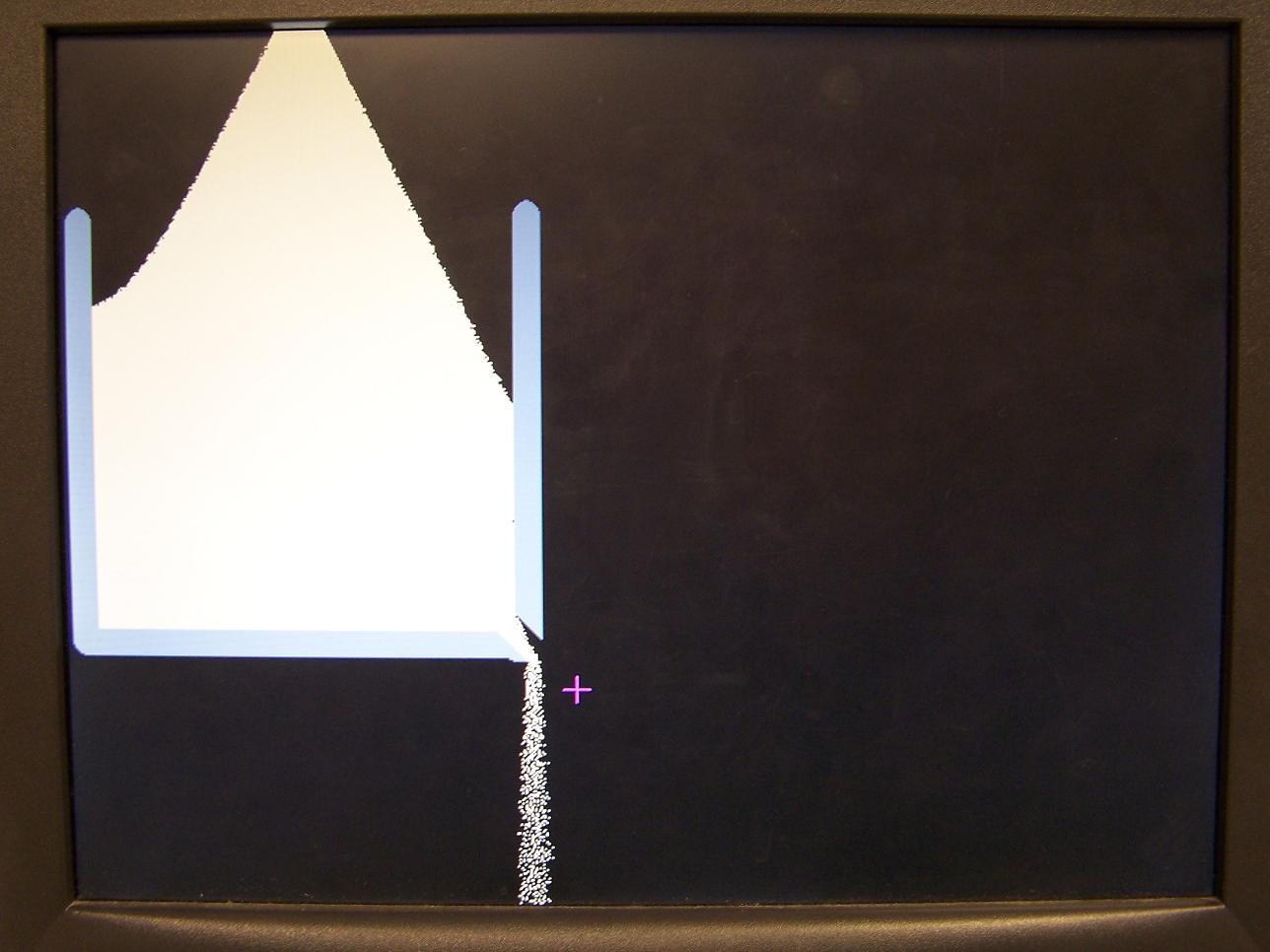
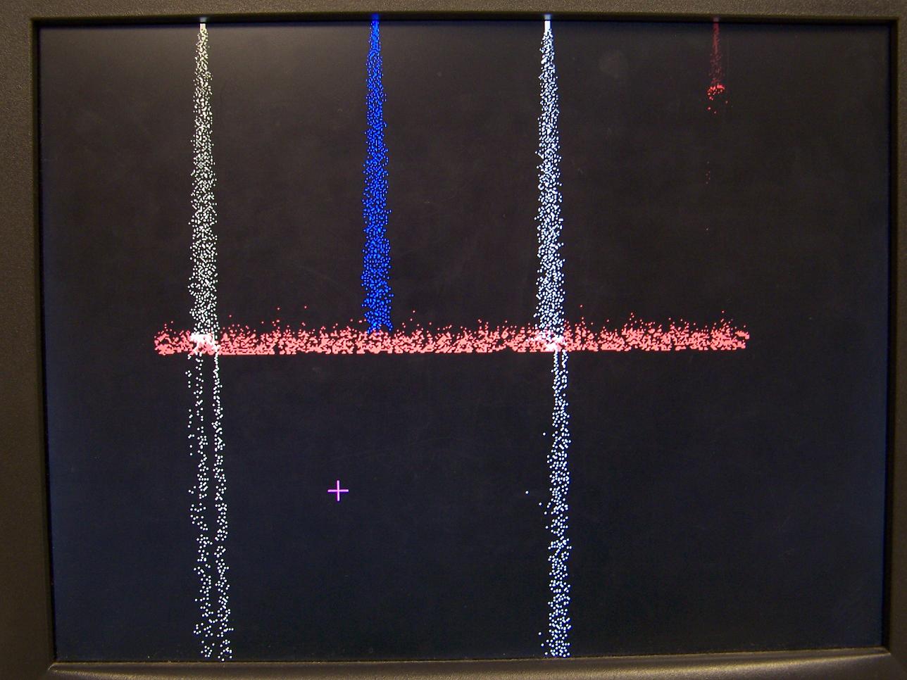
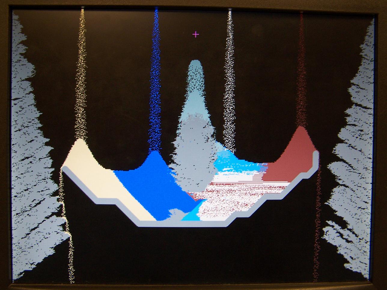
When compared to the behavior of real sand, water, and other modeled particles, there are certainly discrepancies. Most notably, the simulated particles lack a concept of velocity or momentum. For example, Figure 6 shows a case where one would expect the sand flow to shoot out at an angle from the small hole in the wall because of a pressure force from other sand particles, giving the falling ones an initial rightward velocity. However, the simulated particles simply fall down instead.
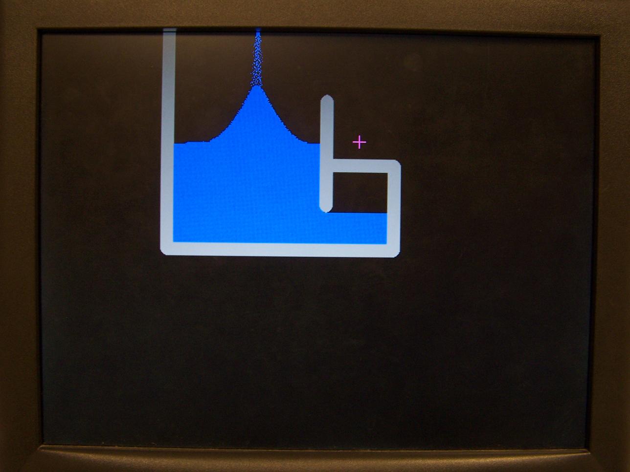
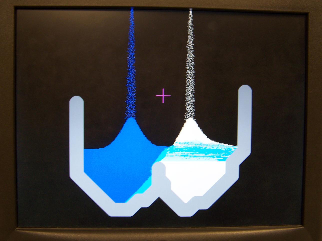
The model also lacks the cohesion and pressure forces expected of fluids. In Figure 7, one would expect the water not to form such a large triangular pile, but rather to spread more horizontally because of the cohesive force and pressure down the center of the pile and outward caused by the particles falling on top. One would also expect it to fill the enclosed gap of blank space. However, the pixels only know their current states, or, equivalently, the particles only know their current positions. They cannot feel forces underneath them or in any other direction, and they can only shift or fall, but never move up.
There are certain behaviors in the simulation that were also present in the Pyro Sand Game. For example, when a torch and water interact, the water is evaporated (becomes blank), but the torch is not consumed. They can be thought of as infinite sources of fire, which is an unrealistic material. Plant and wax particles are also completely rigid, like a solid wall, and the fact that wall particles can remain suspended is unrealistic enough.
However, there are many behaviors that do share convincing similarities to real world dynamics. It is very interesting to watch the streams of sand or salt fall and roll off edges, and one can imagine real sand particles forming a stream as they pour off a similar incline. The tendency for fire particles to rise is similar to the random behavior of rising flames and specks of hot ash that emerge when burning wood. The slowed movements of sand particles in water resemble the buoyancy that would be expected of actual liquids. Most of the proximity transforms, such as salt becoming saturated with water, plants growing, objects burning, or concrete solidifying, were implemented to have a real world equivalent, even if the physics do not accurately match.
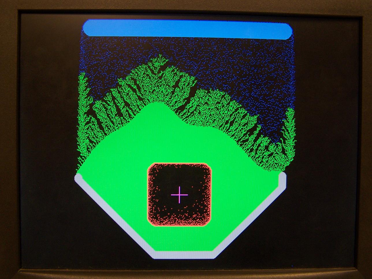
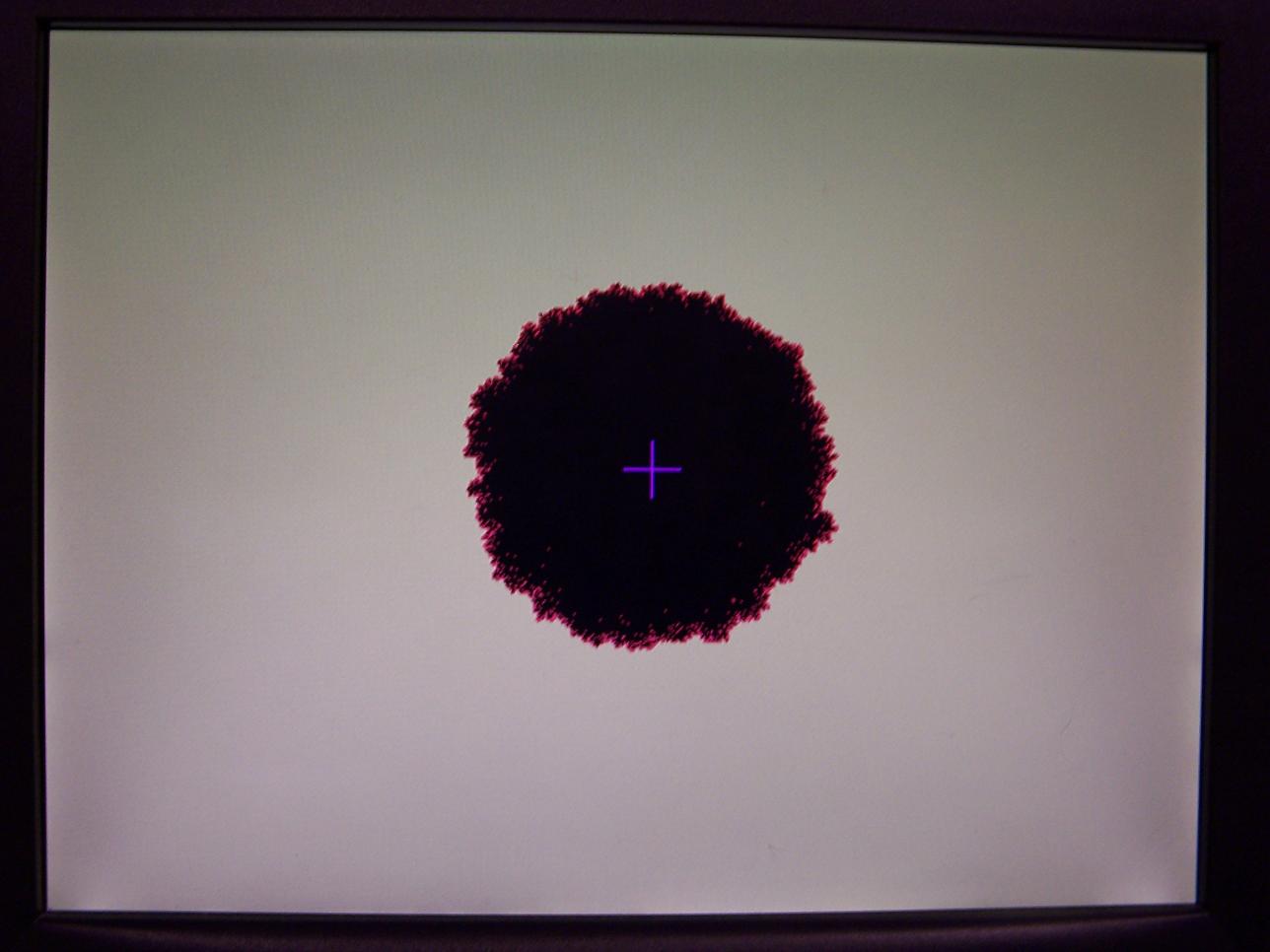
When compared to the Pyro Sand Game, there are certain differences in the macrobehavior of particles that arise from the differences in the source codes. For example, in the Pyro Sand Game, a salt and water particle will both be consumed to form a salt water particle. However, in my project, the salt becomes wet without consuming the water, which allows observation of the Archimedes principle when salt is dumping into a pool of water, but it has the unrealistic effect that one particle of water can wet an entire pile of salt. As another example, in the Java version, plants that grow under a spout tend to grow more diagonal extensions than in my simulation, which can be seen by comparing Figure 2 in the High Level Design section to Figure 8 below at a pixel resolution. This is a result of my implementation of water having only a 0.25 probability of becoming a plant when touching a plant diagonally, but probability 1 of becoming a plant if touching laterally. The rule was implemented to prevent plants from growing in a square pattern across a pool of water, but it biases plant growth in lateral directions. As a related trade off, fire spreads in a square-like pattern across plants in order to guarantee that a connected plant network is completely burned when any of its pixels are lit. This square-like fire propagation is shown in Figure 8.
Overall, the mismatching behaviors between this implementation and the Pyro Sand Game do not make this project "incorrect"; rather, these can be thought of as implementation differences. This simulation still retains some aspects that are believable with reference to the real world and some that are not.
Safety
The DE2 board was always handled carefully in lab on an ESD mat. That aside, there were no inherent major safety risks in this project.
Usability
This game can be played by anyone who is capable of using a standard PS/2 keyboard. Alternatively, the user may flip the switches and press the buttons on the DE2 board, although it is likely to be more difficult.
Conclusions
Meeting Expectations
I was able to create a hardware implementation of a falling sand game, similar to the Pyro Sand Game. This implementation includes 16 different particle types, less 3 of the 4 states required to implement fire and 1 extra state required to implement salt water, for a total of 12 of the particle types drawable in the Pyro Sand Game. The state of all particles in the screen can be updated within a single 60Hz frame to match the rate of the VGA monitor, so that the simulation runs in real time without delays or flickers. The Cellular Automaton model is able to satisfactorily mimic certain particle dynamics similar to the expected behaviors in the real world, although it lacks the concepts of momentum and interparticle forces. Overall, the simulation is easy and enjoyable to manipulate, and I am fully satisfied with the results.
For possible improvements, the CA update rules could be modified to try to implement more realistic behaviors. I have noticed that the Pyro Sand Game does a better job of horizontally dispersing mobile particles, so that they do not form as tall or triangular piles as in my implementation. The reference website mentions that source code may be available, and there is a developer forum on that same website, so it may be possible to determine the exact update rules used in the Pyro Sand Game. Implementing Margolis neighborhoods may be able to introduce the concept of momentum to falling particles, but it would make the screen traversal during each frame much more difficult. Neither of these suggestions would solve the interparticle pressure problem shown in Figure 7, although this problem may be solved by extending the immediate neighbor to be larger than 3 by 3 pixels and then using information from lower rows to approximate whether a particle should feel upwards pressure.
Intellectual Property
Although software implementations of the Pyro Sand Game and other falling sand games already exist, their source codes were not used to create this hardware implementation. The falling sand game concept is not threatened by any patents or trademarks.
This design included a Verilog PLL module created by the Altera Megafunction Wizard. All other files were created by the author from scratch or by modifying examples made freely available by the ECE 5760 course staff and John Loomis.
Appendix A: Photographs


Appendix B: Videos
Appendix C: Verilog Listing
Quartus Archive File and SOF File
CA_Controller.v
CircleROM.v
ColorROM.v
ColorSelector.v
DE2_TOP.v
Input_Controller.v
Keyboard_Controller.v
Particle_Update.v
project_params.h
PS2_ScanCodeReader.v
RAM_256_16.v
Reset_Delay.v
RNG_4b.v
scan_events.h
ScanCodeToEvent.v
SRAM_Controller.v
TempRegion_Controller.v
Troll_Controller.v
TrollROM.v
VGA_Controller.v
VGA_Param.h
VGA_PLL.v
References
Pyro Sand Game
John Loomis DE2 Examples
ECE 5760 Course Website
Thanks
I thank Altera for the DE2 boards used in this course, and I thank Bruce Land for instructing the course and providing VGA and CA examples.