HARDWARE
Graphics
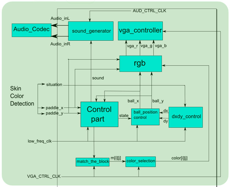
Top module
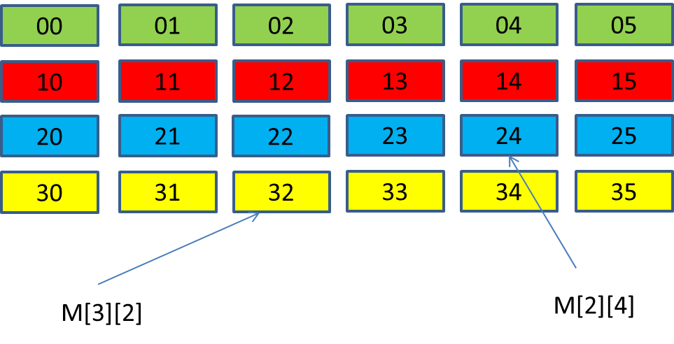
In the top module, a state machine, controlled by the low frequency clock, is responsible for the graphic interface. The movement of the ball is categorized into 4 states: moving up-left, moving up-right, moving down-left, moving down-right. For the state in which the ball is moving up, the ball will either hit the bricks or the wall. For the state in which the ball is moving down, the ball can either hit the bricks, paddle, or the end of the screen (in which case the ball misses the paddle). We use combinational logic to determine whether the ball hits the bricks, the wall, or the paddle and determine the next state. When the ball hits the bricks, the corresponding signals will be set to trigger the change in the brick color and output the sound. Each brick is represented by an index and a value from 0 to 7. When the ball hits one brick, the match_the_block module will give the index of the brick based on the hitting position. If the value of that brick is not 0, then the value decreases by 1. At that time, the brick color fades down by one level. When the mentioned value becomes 0, it means the brick has already disappearred. Thus, the corresponding region is clear and the ball can pass through.
dxdy control module
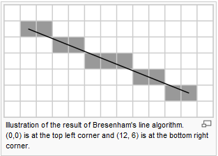
dx and dy together determine the moving angle of the ball. In other words, dy/dx is the absolute value of the line the ball moves along. This module is also clocked by the low frequency clock. dx and dy are determined by the input signal 'situation'. There are 12 possible moving directions in our design. The method we used to generate line tracking is called “Bresenham’s algorithm for line drawing”. The Bresenham line algorithm is an algorithm that determines the points to be drawn in order to form an approximation to a straight line between two given points on screen. In our design, we used a table to store the line-simulating rules of the 12 moving directions based on this algorithm. This module was meant to use when the paddle is tilted. However, since we did not get to tilt the paddle so this module was never used (although we did implement it).
ball_position_control module
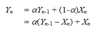
This module is for controlling the position of the ball. Specifically, we used the low frequency clock to control the speed of the ball and a state machine to compute the next position of the ball based on the values of dx and dy.
match_the_block module
Given the pixel position to be displayed, this module outputs the corresponding sequence number of the bricks. We can change the color of the brick using this number as an index.
rgb module
In this module, we used combinational logic to draw the paddle, the ball and the bricks.
sound generator
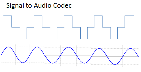
When the ball hits one of the bricks, the signal 'sound' is set, triggering the sound module to send signals to the audio codec. We used the following waveform to simulate an attennuated sine signal.
M4K module
We used Altera Megawizard Plug-in Manage to generate an M4K block, whose data is one bit and address is 19 bits. We drew a 640 by 480 image with a .bmp format. Then, we used MATLAB to generate the corresponding .mif file and imported the file into the M4K block. The stored image will be displayed once the game is over.
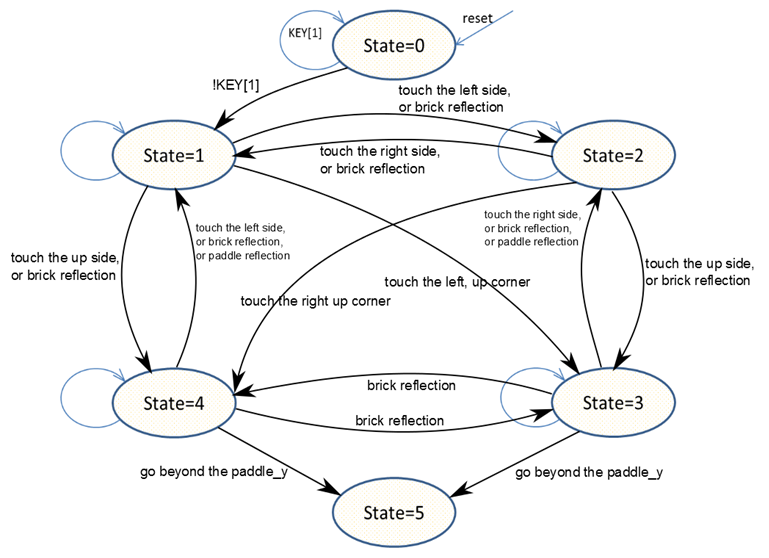
State machine
The following state machine is for the game algorithm.
Skin Color Detection
Main Module
Camera
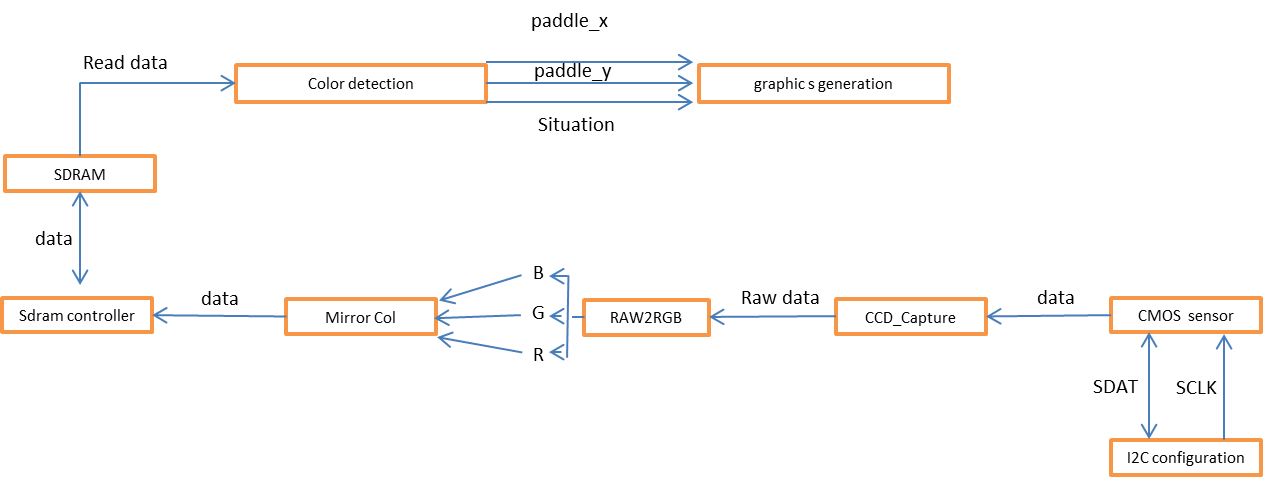
The TRDB_DC2 digital camera connected to DE2 board through an IDE cable is used for this game. We are provided the source code that handles basic functionality of the camera. Video frames captured by the camera are stored in an SDRAM buffer.
CCD_Capture:
This module buffers the data coming from the CMOS sensor and generates the horizontal, vertical, and frame counter, along with the data and the valid signal. The generated frame counter is showned on the 7-segment displays.
RAW2RGB:
In this module, the image data is translated from Bayer format into RGB format. Specifically, the image data is stored in the corresponding Red, Green, and Blue arrays.
Mirror_Col:
This module is used for reversing left and right side of the captured image to match with the real situation.
Skin Color Detection
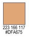
To detect skin color, we first gave the intensity check a wide range to ensure that all skin colors can be detected. However, other colors, such as the reflection of the light or the EST mat, happened to fall into this range. Because of these interferences, the movement of the paddle was not very stable. We tried to adjust the light but it did not help much. Then, we chose the following skin tone as a specific case to test because we thought it was the most neutral skin color.