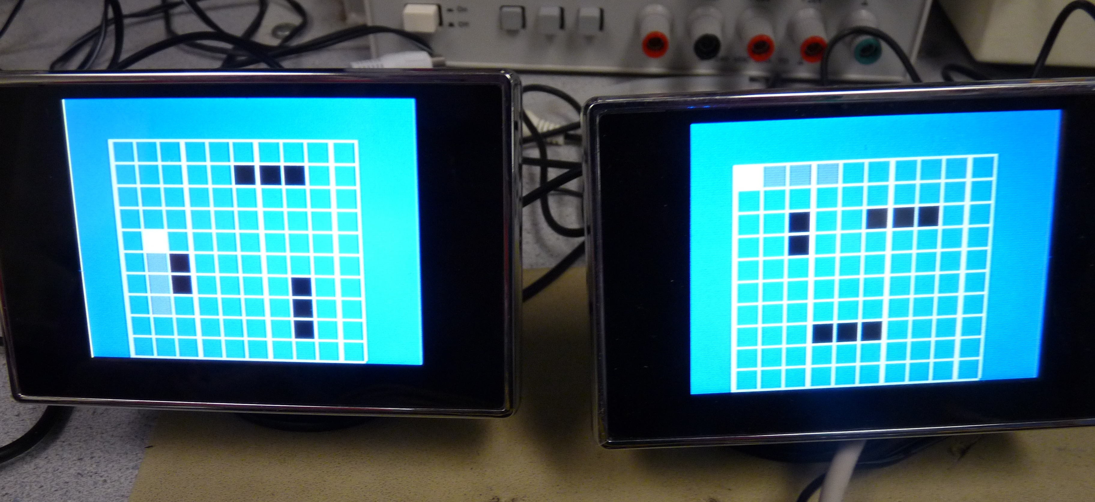
"The classic Battleship game played on two televisions with custom NTSC video generation"
Introduction top
We decided to pursue the problem of generating a color NTSC signal out of the DE2 FPGA board. In order to prove that the VGA DAC was powerful enough to handle this, we wanted to select something that let us use two or more of the output channels. The game of Battleship came to mind as a simple concept that allows two players to have completely separate views.
High Level Design top
Rationale and Sources
The Altera DE2 board has a fairly wide range of inputs and outputs. However, for video, there is only one NTSC input, and only one VGA output. Inspired by projects on generating NTSC video outputs on microcontrollers, we decided to try to expand the capabilities of the DE2 board by creating an easy-to-use color NTSC video generator that would use the VGA output.
Logical Structure
There are several major pieces of hardware that work together to create this game. There are two Color NTSC Generators whose outputs go to the VGA DAC. There is a NIOS II system that runs the game code and draws the two screens. There is an arbitrator module that controls access to the shared SRAM, which is needed by both NTSC modules and the NIOS. And there is a hardware debouncing module for the controller inputs.
The Color NTSC Generators are general-purpose modules that can push color NTSC video out of the VGA connector at full frame rate. They have a resolution of 315x242 pixels. They are set up to allow for array and sequential addressing of the SRAM. In sequential mode, three generators can be used simultaneously with the three VGA output channels using just the 512kb of SRAM.
The NIOS II used in the game is a very simple single-cycle processor running on the FPGA. The system contains the main processor, the interface to SDRAM (where the program code is kept), and a number of Parallel I/O (PIO) modules. These PIO modules are used to receive commands from the controllers and to send data to the SRAM.
The NTSC Generators are time-sensitive, and so they MUST have data ready when they request it. In order to ensure the timing for the NTSC Generators is kept, the arbitrator module controls access to the SRAM. When the generators are on their video sections, the arbitrator gets data for them and prevents the NIOS from writing to SRAM. When the generators are in their sync sections, the NIOS has full access to SRAM.
The controllers for the game are just sets of pulled-down pushbuttons attached to the GPIO header. When a button is pressed, the signal jumps high. However, the button is a hardware device, and exhibits a "bounce". In order to prevent a single button press from being read multiple times, a debouncing module is built in hardware. For a button press, the debounce module checks that the button has been pressed for a certain period of time. Humans can't press the button quickly enough to miss this period, but any bounces will certainly be shorter. The same is true of a release. This four-state state machine eliminates invalid button presses.
High Level Block Diagram
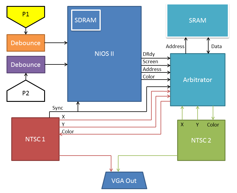
Figure 1. High-level block diagram.
Hardware and Software Trade-offs
The software in this project is entirely used to control game state. The hardware runs the software and controls generation of the NTSC video signals. There are a few places where either software or hardware could have reasonably been used.
Debouncing of the controller inputs was handled entirely in hardware. Oftentimes, this debouncing is handled by software, but for several reasons we decided to rely on the hardware module:
- The NIOS has no interrupts enabled. We would have had to do so in order to generate the appropriate timing.
- In hardware, debouncers can work entirely in parallel.
- The code for the NIOS was getting to be extremely lengthy even without handling debouncing.
Drawing on the screen was handled entirely by software. It would be conceivable to create a hardware module that would receive drawing commands from the NIOS and then draw to the screens accordingly. We chose to stay with the software only approach:
- The purpose of the project was not to generate the fanciest-looking game, but to make one that demonstrates the ability to run two NTSC televisions at once.
- The NIOS is not performing such complex calculations that freeing up processor cycles would make a significant difference in the final project.
NTSC Video Standards
The National Television System Committee (NTSC) video standard was initially created in 1941 to create a set of requirements for video that would have to be followed by every television manufacturer and broadcaster. At this point in time, all televisions were black-and- white (BW), so the signals only needed to carry intensity information. Soon afterwards, development began on color televisions. A new standard had to be set that now carried color information, but this standard needed to be compatible with the old televisions. In order to encode color without preventing the BW televisions from working, the old standard could only be modified, not abandoned, and in such a way that would be functionally identical for intensity-only devices. The way that this was achieved was by overlaying sinusoids on top of the signal that would carry color information. The time average of these signals was zero, so the BW televisions would be able to get the same intensities, while the phase and amplitude of the waves carried hue and saturation information for the color televisions.
Hardware Design & Implementation top
Hardware Overview
The main hardware module for this project is the NTSC video generator. A large amount of math, code, and testing went into making this a functional module. The NIOS II is important for the project as a whole, but is just created using SOPC Builder. Other important modules are the Arbitrator and Debounce modules, whose purposes are important even if their design is simple.
Color NTSC Video Generator
The problem of generating Color NTSC Video begins with understanding the standard. NTSC is an analog standard designed for analog displays, where each row is somewhat discrete, but each "pixel" is not. This means there is a fixed "Y" resolution, but a semi-arbitraty "X" resolution. Each line of NTSC video begins with a synchronization section before getting to actual video information. The breakdown of a single line of NTSC video is shown in the following image:
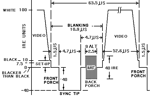
Figure 2. Single NTSC line (source: NTSC-TV.com).
The scale of this image is in "IRE Units", which are defined relative to voltage levels. A change of 140 IRE is equal to 1 volt. 0 IRE is the "Zero Level", while -40 IRE (usually corresponding to 0 volts) is the "Sync Level". The "Black Level" is at 7.5 IRE, slightly above the Zero Level, and the "White Level" is at 100 IRE.
A full screen of NTSC video has 525 lines. Some of these can't be used for video as they only carry vertical synchronization information, but there is yet another complication. The NTSC standard is "Interlaced" instead of "Progressive". This means that 262.5 odd lines are drawn, then the television returns to the top to draw 262.5 even lines. This is used because it tricks the eyes into thinking the refresh rate is twice as fast as it actually is. However, this is not very useful for our projects, so we force the television to use a "fake Progressive" mode. We draw 242 lines, then use the last 20 lines as synchronization to send the television back to the very beginning. We draw 4 blank lines (have H-Sync but no video), then 3 "V-Sync" lines, and then another 13 blank lines. This is enough to force a television to keep re-drawing the same set of lines.
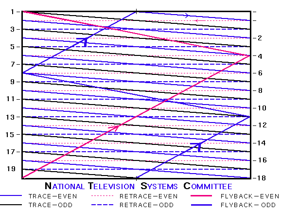
Figure 3. NTSC screen, interlaced mode (source: NTSC-TV.com).
During the first and second stages of testing, the color information was ignored, and a Black-and-White signal was the focus. The NTSC Video Generator is set up as a group of counters, so first, a single line of NTSC video was generated to check timing on the oscilloscope. This was done by calculating line counter values for the various timings of signal sections. Next, a whole screen was generated, and this was tested on the LCD televisions. A line number counter was addded to track the Y position in the screen, and more of these counter values were calculated. Once these two tests were completed, the next task was to add in color.
The color carrier is specified to be a 3.579545MHz sinusoid. It is phase shifted to change the hue displayed, and it is amplitude modulated to change the saturation displayed. In order to "lock on" to the sine wave's frequency and phase, 8-10 cycles of "Colorburst" are required during the setup of each line, in the Back Porch. Televisions have a phase-locked loop which captures this colorburst. On the broadcast side, companies use a temperature-compensated oscillator to get within a few Hz of the specified frequency. It is not possible to get this frequency exactly on the DE2 board without using external hardware, but a multiple of this frequency can be reached to within 0.02%. The 50MHz clock can be fed into the Phase Locked Loop (PLL) to be multiplied by 29/27, which outputs a 53.703703MHz square wave (15 times the color frequency is 53.693175MHz). This is too slow to reasonably run a sine wave lookup table, so we use square waves instead. As it turns out, this works just fine, and color video was being displayed on the screen. There is some unexpected behavior in which a hue input of 0 corresponds to yellow rather than red. It is possible that this is caused by the slightly incorrect colorburst frequency. The operation is consistent, though, so we are not worried about changing anything.

Figure 4. Available color palette.
Once we had the video set up, the remaining task was to allow this module to control SRAM access. The final version of the Color NTSC Video Generator module adds addressing and control outputs. There are two addressing modes available. The first is an array mode, where an x index and y index are output. These can then be concatenated into an SRAM address. This makes getting addresses easy, but does not make efficient use of SRAM space - only two screens can be run with this addressing method. The second is continuous mode, where every pixel's address is its index into the screen. Then multiple screens can be addressed by adding an offset. Using this addressing method, three full screens of video can be kept in SRAM, assuming the color information is shortened to just 16 bits.
The control outputs of the module contain information about synchronization sections. The H_Sync output is high when the generator is in a horizontal sync section, and the V_Sync output is high when the generator is in a vertical sync section. The Sync output is high when either of these outputs is high. Unlike the VGA system, these Sync outputs are not used to generate video. Instead, they can be used to determine when SRAM can be freely accessed. The last control output is the lookup clock. It goes high to signal that data is needed by the NTSC Generator. The next time it goes high, this data will be latched in, and new data is requested. In order to make sure data is ready for the first pixel in any line, this output will signal 9 cycles before the start of video. The H_Sync line also goes low 9 cycles early to match the lookup clock.
A method unused: Quadrature Oscillator
The initial plan for the Color NTSC Video Generator had some significant changes from the system we ultimately implemented. The largest change was the method of modulating phase and amplitude. Most video generators employ a Quadrature Oscillator. This is an oscillator consisting of two sine waves 90 degrees out of phase. The amplitudes of the "In-Phase" and the "Quadrature" waves are varied, and then the waves are added together to produce the shifts. We initially pursued this system, but discovered that we could not run quickly enough. The operating frequency had to be a multiple of 4 to allow for a 90 degree phase shift, had to be a large enough multiple to properly sample a sine wave, and needed to be very close to a multiple of the Colorburst frequency. The only multiple that satisfied these conditions was 28, and we discovered that the system could not keep up at this speed.
The Quadrature Oscillator was scrapped, we moved to square waves, and our multiple shrank all the way to 15. We haven't noticed any issues with logic speed since.
Multi-Screen Arbitrator
The Multi-Screen Arbitrator module fully controls access to the SRAM. It needs to ensure that each NTSC Video Generator module gets data when it needs it, and it needs to allow the NIOS to write to SRAM as quickly as possible.
The Multi-Screen Arbitrator module we created was a fairly simple version. The two NTSC modules run entirely in parallel, so just one set of Sync lines is sufficient. When the Sync line is high, the NIOS is permitted to write to SRAM. When the Sync line is low, the Arbitrator continually retrieves data for one screen, and then the other. Addressing of the two screens is handled by concatenating the screen number, the y-coordinate, and then the x-coordinate. Because the y-coordinate only goes to 242, it can be held within 8 bits, leaving room for the screen bit.
When the NIOS wants to write data, it puts valid data on its outputs and then sends an edge on a ready line. It will wait to send this edge until the SRAM is available. When the Multi-Screen Arbitrator receives the ready edge from the NIOS, the NIOS data is latched in to registers that write to SRAM.
If more work were put into this module, it could be made to run much faster. Only two out of every nine cycles during video generation are needed to retrieve NTSC data, so theoretically the other seven could be used for writing to SRAM. A queue could also be implemented to prevent the NIOS from waiting for the SRAM to be available. If the extra seven cycles are made available, though, this queue would probably be unnecessary due to the relative speeds of the NIOS and the Arbitrator module.
Hardware Debouncer
Due to the nature of pushbuttons, a button press is susceptible to "bounce". When a button bounces, the voltage on the line jumps up and down before finally settling. This can cause a press, and even a release, to be incorrectly interpreted as multiple presses.
To prevent incorrect button readings, a simple state machine is implemented in hardware for each controller input. A button must remain pressed for a minimum period of time to be considered "pressed", and cannot be pressed again until it is "released" for a certain amount of time. The input clock is slowed down to a human scale and a four-state machine is created.
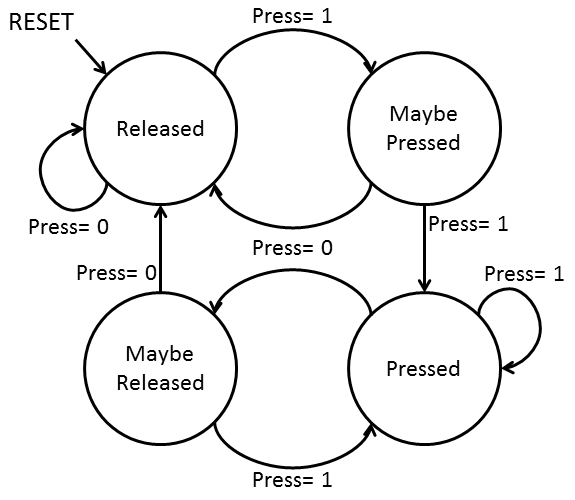
Figure 5. Debounce state machine.
Software Design & Implementation top
NIOS Image Generation
A NIOS II standard level soft processor (herein referred to as the processor) was implemented in hardware on the DE2 board. The purpose of the processor was to execute the C code that controlled the logic for the Battleship game. The processor contained several input and output signals that communicated with the external hardware (i.e. the NTSC video generator, arbitrator, and debounce modules) in order to pass video data back and forth. The table below summarizes these signals and describes them as input to or output from the processor.
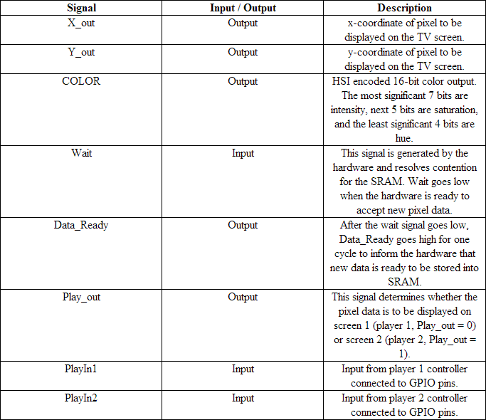
Table 1. Table of NIOS signals.
The following image captures the setup for the NIOS II processor that was created in SOPC builder.
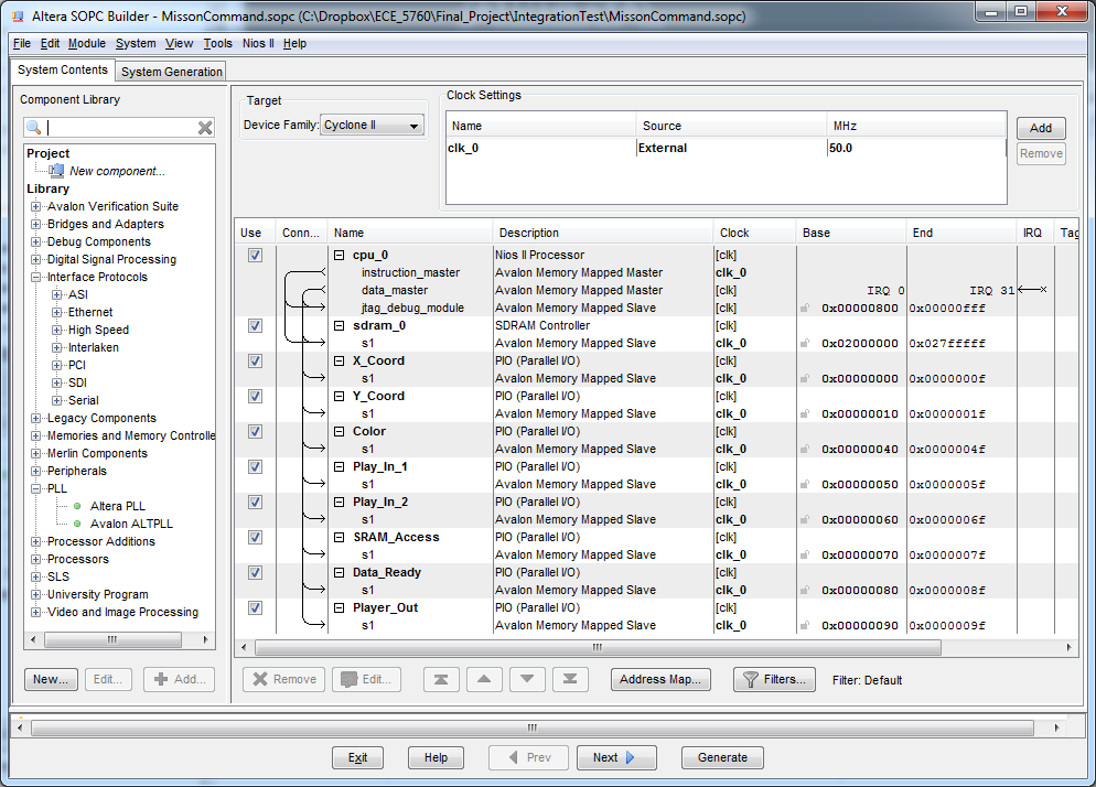
Figure 6. NIOS setup in SOPC builder.
Gameplay
The Battleship gameplay can be divided into four overall categories that occur in sequence: initialization, entering ship locations, entering strike coordinates, and post-gameplay. The function and logic details of each section are explained below.
Initialization
The initialization code initializes all of the system variables to their proper values and sets the game up to be played. This involves clearing out the ship and shot location matrices to zero, resetting each players current coordinates to (0,0) and orientation to 0 (right), resetting the hit counts to zero, and clearing out any input from the controllers. After the system variables have been reset, the screen is cleared to all blue and a 10x10 white grid is drawn on each of the two screens. A model of the gameplay grid with cell locations labeled is shown below.
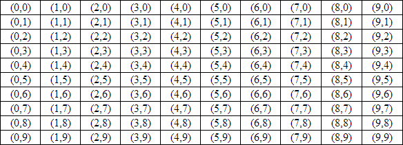
Table 2. Game grid layout with labeled cell locations.
Enter Ship Locations
This section of the gameplay code allows each player to enter locations for each of their 5 ships. There is a destroyer with length 2, a submarine with length 3, a cruiser with length 3, a battleship with length 4, and an aircraft carrier with length 5. The ships are entered in this order. As the ships are being entered, both the player 1 and player 2 controller inputs to the GPIO (which are debounced and sent to the NIOS) are polled. These inputs affect the current cell location (indicated in yellow) as well as the location of the trailing cells (indicated in gray) based on the current orientation. If a rising edge on any of the inputs is detected, the location of the ship is moved accordingly if this is a legal action. For example, if the destroyer is at location (4,8) on the grid with an orientation to the right and the player input is down, then the ship moves down to location (4,9) and maintains its orientation. However, if the destroyer is at location (4,8) on the grid with a downward orientation and the player input is down, this would not be a legal action since this would move the ship’s location off the grid. All boundary conditions are checked for each of the player directional inputs (up, down, left, and right). All boundary conditions are also checked for rotational inputs as well. For example, if a ship is at location (4,9) with an orientation to the right and the player input is rotate, then a 90 degree clockwise rotation would cause the ship to be located partially off the grid. The system does error checking to recognize potential illegal actions such as this and prevents them from occurring.
After each ship has been entered, the ship’s cells turn black to indicate that the ship has been placed in that location. As each successive ship is entered, not only do boundary conditions need to be maintained but error checking must also be in place to prevent a ship from being placed in the location of another ship that has already been placed. Each time that a new cell is being drawn to indicate the location of the ship currently being placed, a function is called to determine whether or not the current cells and trailing cells are in the same location as any of the previously placed ship. If they are not, the appropriate cell color is drawn: yellow for the current cell and gray for the trailing cells. If any of the current or trailing cells is in the location of a previously placed ship’s cells, the cell is drawn red to indicate that this cell is taken and that the current ship’s location is not valid. In addition to this visual indication of taken cells, the system also does error checking to prevent the ship’s location from being entered while in an invalid location. The system will continue to poll for inputs (up, down, left, right, and rotate) until the ship is in a valid location and the user presses the select button. This phase of the gameplay continues until both players have entered all 5 of their ships.
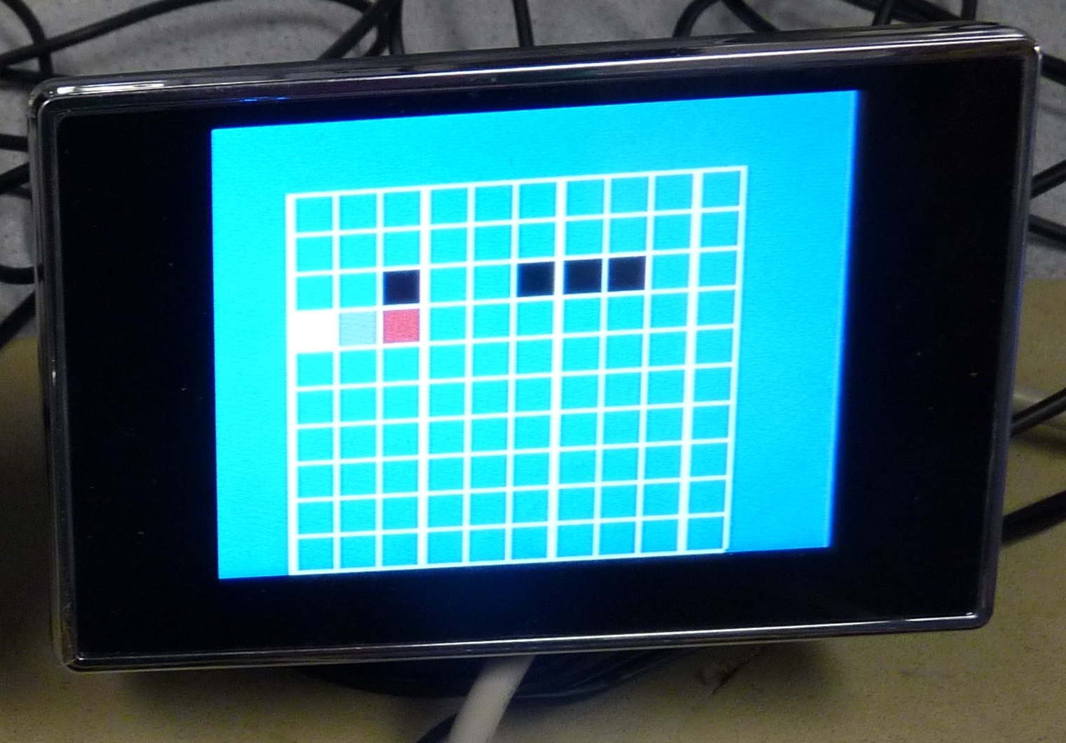
Figure 7. An invalid ship position due to overlap.
This section of the code was the trickiest part to write and required the most amount of code and intricate attention to detail. Many aspects of this code were tricky to write and required testing a few different methods before obtaining efficient and correct execution. Before any ships could be entered, a properly debounced single input signal per button press was needed by the processor. This turned out to be a more suitable task for hardware than software, since a dedicated debounce state machine module could be applied to the GPIO inputs from each player’s controller. Something we tried that did not work was using Altera’s IO read function to read the input. This was because the input was continually read in a loop until the input signal was no longer high, which was multiple cycles. For example, if a player pressed the down button then the current cell would immediately traverse down to the bottom row as if the down button has been continually pressed. To avoid this, we checked for a rising edge using edge capture instead of checking whether the signal was high or low. Since there is only one rising edge per button press, each input is executed only once which solved the issue. Another tricky aspect of the code was the great deal of error checking that was necessary to maintain boundary conditions and prevent a ship from moving to or being entered in an invalid location. Error checking was functionalized for each of the ships which made this task more manageable. For example, functions were written for each of the ships of length 3, 4, and 5 which individually checked to see if any of the current or trailing cells were taken. Functionalizing these tasks made it easier since the number of trailing cells to check (based on the ship’s length) was parameterized based on which ship was being entered. Another tricky aspect of this section of code was managing both players’ inputs while different tasks were being conducted since processors execute in a serial manner. As a result, each player must be finished entering their respective ship before the next ship may be entered. This helped to simplify the code and allow a more logical control flow. Lastly, maintaining efficient and optimized data movement between the processor and the hardware was tricky. A handshaking scheme was established which allowed the hardware to avoid contention issues for the SRAM and avoided the necessity for creating accurate timing schemes for when data can and cannot be output to the hardware. In this manner, the processor waits to pass data to the hardware until the hardware signals that the SRAM is available. When the data is output from the processor, a ready signal indicates to the hardware that new data is available and valid to be read into SRAM. Lastly, the color data encoding scheme was optimized to allow much faster screen updates and more efficient gameplay. Originally the hue, saturation, and intensity values were encoded as separate output signals. By combining them into a single encoded data output signal, the system saved multiple cycles for each screen pixel write by only having to prepare one output per pixel instead of three. This allowed a full screen’s worth of pixels (315 x 242) in approximately 50% of the time needed when color data was encoded as three separate signals.
Enter Strike Coordinates
This phase of the Battleship game is executed after each player has entered valid locations for all five of their ships. The purpose of this phase of the game is to allow both of the players to alternately enter cell locations for strikes and display whether or not the strike was a hit or a miss. When it’s one players turn to strike, that player will see a view of their previous hit cells in red and miss cells in green. The current cell for the next strike is also displayed in yellow. The player uses the up down left and right directional buttons on their controller to move the current cell around. When a strike location is set, that player pressed the select button to enter a strike. If the strike location is a hit then the cell turns red. If the strike location is a miss then the cell turns green. Meanwhile, the screen of the player who is not entering a new strike displays their current arrangement of ships as well as the hit and miss location of the player entering a strike. When the player enters a new strike, the new hit/miss cell is shown on the other player’s screen as well. After an approximate 5 second delay the screens clear and display the opposite information so the other player can enter a new strike. This will continue until one player has obtained 17 hit strikes (2 + 3 + 3 + 4 + 5 cells for all the ships = 17). When a player has won (obtained 17 hit strikes), their screen turns green and the loser’s screen turns red to indicate that there is a winner and who has won/lost.
Error checking was necessary for this phase of gameplay as well. Boundary conditions were maintained to ensure that a strike could not be entered in a location outside the 10x10 grid. This was slightly easier to maintain than the boundary conditions in the entering ships phase of the game since there was only one cell to check and no trailing cells or orientation to be concerned with. Error checking was also needed to ensure that a strike was not placed in the location of a previous strike. If this occurred, execution would continue and prevent a strike from being entered in that location.
The trickiest part of this section was ensuring that everything was displayed properly at all times. Ships and shots had to be drawn and redrawn at appropriate times to ensure that everything that should be visible is seen and only at the right times. For example, when the current cell crosses over a hit or a miss cell, the hit or miss cell must be redrawn red or green when the current cell is moved. In addition, the hits and misses must be drawn after the ships are drawn so that the ship locations do not supersede the strike location display.
Post-Gameplay
A player has won the game once they have successfully obtained 17 hit strikes, which would “sink” all of the opponent’s ships. Once this occurs, the winner’s screen turns green and the loser’s screen turns red to indicate who has won and who has lost. After the game ends, the system can be reset and the game can be played again by pressing any button on either of the two controllers. This sets the system back to the initialization phase of the game which resets all of the variables and allows a new execution of the game.
Results top
Speed of Execution
In order to display images on the TV screens, the NIOS outputs pixel coordinates and color data to the hardware video generator. Timing is controlled by low-level signals that indicate when the NIOS has access to the SRAM and when valid data is being output by the NIOS to be read by the SRAM. Using optimized communication and encoding schemes, we are able to update our video signals with no noticeable hesitation or flicker. There are no artifacts on the screen and the colors show up bright and distinct with good contrast. When clearing all of the pixels in the entire screen, there is a slight noticeable “screen wipe” effect as rows of pixels traverse from the top to the bottom of the screen and fill in the corresponding color. However, this process of writing to every pixel on the entire screen takes approximately one second. This causes no impact on the gameplay and only occurs when the game is reset and when the game alternates between whose turn it is. The majority of the gameplay only involves updating specific cells, such as when a player is entering ship locations or entering coordinates for a new strike. Updating individual cells during these aspects of gameplay is instant (more quickly than the human eye can discern color changes) and occurs seamlessly, with no flicker or hesitation.
The Battleship game requires integrating actions from two players into the same game with concurrently running displays. Both players are performing actions in the game simultaneously, such as entering new ship locations. These concurrent actions are handled by the NIOS. The operating speed of the processor system clock allows the NIOS to poll for inputs quickly enough to handle simultaneous reading of inputs from both players. This was further optimized by making all 6 button inputs for each player separate bits of the same port, making only two 6-bit input ports to read instead of 12. By using simple edge capture supported by Altera’s parallel input-output (PIO) module, rising edges on both ports can be read virtually simultaneously. Once read, the NIOS may respond accordingly based on which pins on the two input ports are asserted. Both input ports are debounced in hardware before being sent to the software, allowing the software to perform effective and clean edge captures. The debounce module works very well, only allowing one input rising edge per button push (even if the button is held) and creating a priority encoded input scheme that responds with a reliable signal for every button push. This allows for smooth and efficient two player concurrency, with no lag from either the NIOS gameplay software or the hardware-based NTSC video generator.
Accuracy
The video generation output produced a highly accurate image for what was trying to be achieved. As mentioned in the hardware section, the color carrier video signal is within a 0.02% margin of error which creates no discernible change in the output signal displayed on the TV screens. In addition, a square wave was generated instead of a sine wave since the signal is too slow to execute an accurate sine wave lookup table. Once again, this change had no noticeable effect on the output. Lastly, the accuracy of the hue color palette is slightly shifted. Instead of a hue of 0 corresponding with a red output it generates a yellow output. This shift in colors based on the input hue was of no concern since the accurate and bright colors could be displayed using these shifted values, and the colors were consistent every time they were generated.
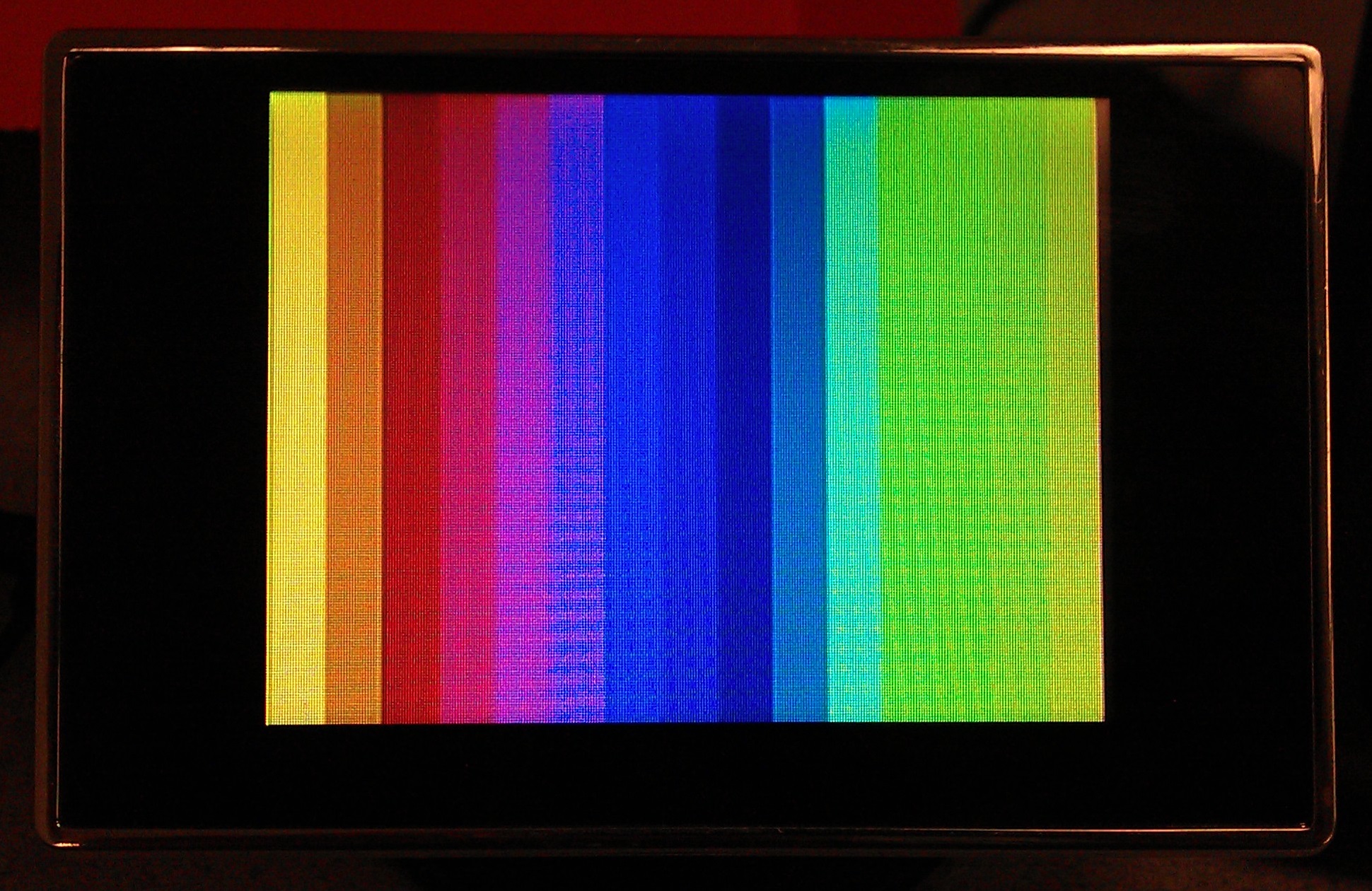
Figure 8. Colors produced by the NTSC video generator. Artifacts are due to the camera and are invisible to the human eye.
The TV output video display was also accurately displayed based on the x- and y-coordinates given as well as the hue/saturation/intensity encoded color signal. Colors were accurately displayed and looked bright with good contrast. In addition, color updates were very quick with no inaccuracies in the color signal when changing quickly between any two colors in the same pixel. There was also no running or bleeding of colors into one another—each color was very distinct with sharp cutoffs and good pixel resolution. Lastly, the color signal that was generated was analog and we were displaying this analog signal on a digital TV screen. This digital TV screen has a discrete set of pixels that are used to display the input video signal. Due to this analog/digital conversion and the pixel resolution that was used to display our images, certain pixels would not show up if only drawn one pixel wide. For example, we originally used lines with one pixel width to generate the grid. However, certain lines in the 10x10 grid structure were attempting to be displayed in between available discrete pixels on the TV screen. This would prevent them from being displayed and caused inaccuracies in the output. This problem was easily remedied by ensuring that no image being displayed on the TV screen was less than two pixels wide. Each of the lines in the grid is two pixels wide, and each of the cells being displayed are 20x20 pixels length by width. This created bold and clean looking video outputs where all edges and images could be easily viewed and discerned from one another.
It is worth noting that the Color NTSC Video Generator was only tested with one specific model of television. It is possible that other devices may not be as forgiving about the colorburst frequency. If further testing reveals this to be an issue, the only feasible solution with the given hardware is to obtain an external oscillator module. This will require a re-calculation of the NTSC parameters.
Usability
The project we created used our take on the classic battleship game to display the proper functionality of a two output full color NTSC video generator module. The game is fun and easy to use for anyone. The controllers are intuitively set up to allow easy input and manipulation of the games functions. Extensive error checking and strictly enforced boundary conditions ensure there are no bugs and that the user cannot perform and illegal game actions such as placing the ship past the edges of the grid or on top of occupied cells. Other aspects of the game are also highly intuitive to indicate to the users exactly what is going on in the game at that moment. The current cell being moved around by each player is displayed in a bright easy to see yellow color. Each one of the trailing cells of the ship is displayed in gray which allow the user to know how the ship is going to move when the rotate button is pressed. When each ship is entered, the cells all turn black indicating that they have been entered and can no longer be moved. When a user attempts to place one ship over cells with an existing ship, the cells that are occupied turn red. This clearly indicates that this would be an illegal game action and the system does not allow the ship to be entered in this location. During gameplay, each screen displays the appropriate information based on whose turn it is. The player who is entering new strike coordinates sees each one of the cells where previous strikes were entered. The cells are green if they are a miss and red if they are a hit, which also help to create an intuitive interface. The player who is not currently entering a new strike sees their own ships with the opponents previous hit and miss strikes along with the current hit/miss strike after it is entered. Once one player wins by sinking all of the opponents ships, the game automatically displays solid green on the winner’s screen and solid red on the loser’s screen, indicating the game has been won and who the winner and loser is. To reset the game and play again, either player can press any button on their controller to automatically reset the game. We believe that with most people’s general knowledge of the semantics of the classic battleship game along with the highly intuitive controls and displays, anyone can easily have hours of fun using our game.
Conclusions top
Final Thoughts
The DE2 boards did impressively well with generating NTSC video signals. The Color NTSC Video Generator we created appears to work well, and seems to be easy to use. The only thing we found really surprising was the amount of work that went into making the game source code. What we believed to be a simple game turned into nearly 10,000 lines of C.
Conforming to Standards
The main standard we were conforming to was the NTSC color video standard. We did not implement a full color NTSC video generator, but instead used a simplified version that ignores the interlacing aspects of NTSC video. However, this is something that has been done by large companies in the past, so this is not an issue in the slightest. The bigger concern might be our use of a nonstandard Colorburst frequency. Although it worked in the lab, we only tested on one model of television. There is no telling whether this might fail on some other NTSC televisions.
Appendices top
A. Source Code
Top-level file:DE2_TOP.v
NTSC Color Video Generator:NTSC_Color_Generator.v
- NTSC Color Video Parameters:NTSC_Param_Square.h
Multi-Screen Arbitrator:MultiScreenArbitrator.v
Debounce Module:HWDebounce.v
Project Archive (Quartus):Battleship.qar
Battleship Code:Battleship.c
B. Schematics
The controllers are extremely simple I/O devices. Each button is mapped directly to a pin on the GPIO header through the following circuit.
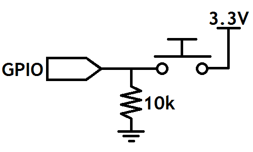
Figure 9. Basic pull-down circuit for controllers.
C. Specific Task Breakdown
| Joshua Schwartz | Both | Michael Ross |
|---|---|---|
| Battleship Code | Debounce Module | NTSC Generator |
| Debugging | Arbitrator | |
| Website Content | Controllers |
References top
This section provides links to external documents, code, and websites referenced and used throughout the project.
Websites
Published Works
- Television Engineering Handbook, Benson Rev Ed. Mc Graw Hill - available in Cornell library
- Video Demystified, K. Jack (Brooktree's Guru) Hightext - available online through Cornell library
Acknowledgements top
We would like to thank the following groups and people:
- Bruce Land, for being one of the best instructors in Cornell engineering
- Our TA, Annie Dai, for helping us get through our lab assignments
- Altera, for providing the hardware for our project
- Hasbro, for creating the game that inspired us
