Introduction top
"Additions to existing Pancake CPU of hardware return address stack and basic vector support"
For my ECE 5760 final project, I developed hardware extensions for the CPU used on the Altera DE2 boards in ECE 5760, the Pancake CPU. The Pancake CPU was originally developed at the University of Hiroshima by K. Nakano, et al., and adapted for ECE 5760 by Bruce Land. The Pancake CPU is an alternative to the Altera IP processor, the NIOS II, which is provided through the Altera software. An FPGA developer can write C code, instantiate a NIOS II on the FPGA using the Altera toolchain, and run the C natively on the NIOS II. Writing directly in C can be advantageous, but the CPU provides many disadvantages. The NIOS II takes up many logic elements on the FPGA as well as significant amount of memory bus usage. Additionally, the toolchain needed to properly use the NIOS II can be very confusing to understand. The Pancake CPU, on the other hand, only requires around 1100 logic elements on the DE2, which is less than 3.5% of the available logic elements. The Pancake CPU operates out of a single M4K RAM block, so there is no bus traffic generated by the CPU. Also, there is no toolchain to use - a developer just needs to instantiate a Pancake CPU using the provided source code can start developing software.
One of the disadvantages to using Pancake is that code has to be written in a language developed by Bruce Land called Syrup. The Pancake is a stack based CPU, so the Syrup language takes a little getting used to, but it is relatively simple to learn to program in Syrup. While the Pancake CPU achieves its goal of being a small and easy to use CPU for the DE2 board, it is lacking in performance. It only supports a small instruction set, as the instructions are not very wide, and the bus-based architecture can be somewhat limiting. For my ECE 5760 project, I improved the performance of the Pancake by adding a hardware return address stack and adding a vector multiply and accumulate instruction to the ISA. The ISA changes make previously compiled Syrup code no longer backwards compatible, but the syntax of the language did not change. Recompiling Syrup code to use on the new Pancake will increase performance by speeding up function calls, and all other algorithms will still work exactly as originally programmed.
It might be slightly frustrating to recompile Syrup code to run on the new Pancake, but the performance benefits are worth the extra compilation. Function calls originally required 8 instructions to manage a software return address stack, and required 9 instructions to return. The new implementation only requires a single instruction for call and a single instruction for return. Similarly, running a multiply and accumulate operation, one of the most basic and useful signal processing operations, on a pair of vectors originally had to be performed in entirely software. The software implementation of this operation on the Pancake takes 9 + 18N cycles for the entire vector, whereas my implementation completes in 2 + 2N cycles, which is significantly less than the original software implementation. This is an exciting development for the Pancake, because it is now possible to perform basic signal processing fast enough for useful real time signals, such as CDs.

Updated Pancake CPU Architecture
High Level Design top
Rationale and Source of Project
One of the most important concepts in computer engineering is understanding all of the tradeoffs associated with hardware changes. I had the opportunity to work with the Pancake for the previous ECE 5760 labs. This CPU demonstrated how for only a very small number of logic elements, we could add software support to a system to enable certain functionality that is only easily achieved in software. This CPU presented a tradeoff of significantly more functionality (software support) for comparatively few logic elements (less than 3.5% of total). Due to the small number of logic elements, an FPGA design can instantiate many Pancake CPUs in order to perform multicore functions and develop parallel applications. However, the language that runs on the Pancake CPU is relatively limited. While the language is Turing complete, some aspects of operation, such as function calls and vector operations, are very slow and some algorithms are difficult to write in the stack based language.
The other available full CPU on the Altera DE2 boards is called the NIOS, and it is neither small nor easy to instantiate many CPUS. This CPU provides the benefit of being able to write in C as opposed to a Pancake specific language, but it is very difficult to interface with and takes up large number of logic elements on the FGPA.
Given that the only available CPUs were at two extreme ends of the spectrum - lightweight and low functionality/performance, and high performance with a large footprint, it seemed to me that there was a better balance that could be struck between these two extrema. I sought out to modify the existing Pancake CPU design and ISA to be able to improve the areas of performance that are lacking. Clearly, adding additional hardware and changing the compiler to support these changes does not come free - changing the ISA eliminates backwards compiled code compatibility, and adding hardware increase the number of logic elements required. However, it seemed like there were ways to improve CPU performance that are worth the increase in Pancake size.
Background Math
The hardware extensions to the Pancake CPU effectively offload work from the software to the hardware. Because I targeted specific behavior with my extensions, it is easy to calculate the performance gains from the expected behavior. First, the existing compiler support of calling a function takes 8 instructions, whereas the code to return from a function takes 9 instructions, for a total of 17 instructions per function call. Additionally, the code to set up the software return address stack takes an additional 4 instructions and takes 16 memory addresses at the top of memory to hold the software return address stack. For my hardware modifications to be worth it, the new call/return structure needs to operate in fewer than 17 cycles. Depending on how much extra memory is used, it is possible to justify using additional memory addresses if function calls are sped up significantly.
The structure for indexing arrays in Syrup, the name of the higher level software support of Pancake, is very slow, so the performance gains from the hardware vector support will be large. Due to the time constraints of the design project, only a multiply and accumulate function was implemented. In general, a multiply and accumulate instruction takes two vectors and a length, and for each element in in the vectors, multiples the two elements at index i together, and adds them to an accumulate variable. In the original implementation, running this algorithm required a loop to move through the vectors, and required a complicated scheme to index the vectors, even though the vector memory access pattern was a unit stride. All in all, the original multiply and accumulate software implementation needs to initiate the accumulate and loop counter variables (4 instructions), 18 instructions per loop iteration, and an additional 5 instructions for the loop exiting behavior. This totals to 4 + 5 + 18N instructions, where N is the length of the vectors to multiply. The best way to improve performance is to reduce the term multiplying N, so as long as my implementation achieves this, it will be successful.
Logical Structure
The addition of the hardware return address stack (RAS) and the multiply and accumulate instructions were decoupled, in terms of hardware used. As such, the RAS was completely designed and tested first, and the multiply and accumulate (MACC) was implemented second, and the two sets of new instructions did not use any of the same new modules. However, one of the main design considerations for the extensions was to not significantly modify the existing Pancake structure. The basic Pancake is a very lightweight CPU, and the extended version can be most useful by improving performance without having to add on bulky modules. The RAS uses the existing pcout and pcnext structure to read and modify the program counter, but it instantiates a modified version of the data stack as the hardware RAS and uses two more signals to handle when to pop and when to push the program counter.
The MACC instruction, on the other hand, required significantly more hardware additions than the RAS. The goal of the multiply and accumulate operation was to take advantage of the unit stride memory access pattern of the vectors in such a way that did not require a separate set of instruction or instructions to perform each iteration of multiply and accumulate. It would have been very difficult to develop an instruction that performed a single multiply and accumulate, and then made the compiler break down a multiply and accumulate command into the appropriate set of these new instructions. Instead of implementing a compiler solution, MACC was added as an instruction which took a vector length as one of the parameters, and upon seeing this instruction, the CPU is put into a sub-state machine, which has a separate decoder and uses a few extra registers for the vector addresses and the actual multiply and accumulate value. In this state machine, the CPU pull the base vector addresses from the data stack, and sequentially loads the vector elements, multiplies them, and accumulates them. The first cycle in this state machine clears the accumulate value, and the last one pushes the ending value to the stack. Once the vectors have been proceeded, the CPU jumps back to the regular execution state. Although only the MACC instruction was implemented, the general structure of how to process vectors can be easily applied to other vector based operations.
Hardware and Software Tradeoffs
The goal of this project was to improve software performance through adding additional hardware. Throughout the project, the relevant question was always "how will adding this hardware improve performance?". As mentioned briefly before, it is possible to make the compiler do more work to generate more efficient code, but in the end performance is measured by how many cycles it took to execute a program, and not how smart or complicated the compiler is. As a result, adding hardware complexity to decrease the number of cycles necessary was always chosen in favor of adding compiler complexity.
In the case of the RAS, the tradeoff was pretty easy to understand. By adding the hardware RAS and removing the software RAS, another two instructions had to be added to the ISA (call and ret), but the number of instructions that had to be executed to call and return from functions was drastically reduced. The syntax of the Syrup code was not changed, but the way the compiler handled function calls was drastically changed. Changing the compiler provides the benefit of speeding up performance while simultaneously hiding the hardware changes to the user writing software. Adding the RAS did slightly increase the footprint of the Pancake, but it was able to provide a tremendous benefit to execution time for all Syrup programs without having to rewrite any Syrup Code
Unfortunately, if a piece of software wants to use the more efficient MACC instruction, the software has to be rewritten to use the instruction. The benefit of the old implementation of multiply and accumulate is that the user writes the code in a way that looks intuitive - it has a loop, it accesses each array, it multiples two numbers, and accumulates them. With the new macc implementation, a user has to specify variables as vector type variables, he or she then has to push the base address of the vectors on to the data stack, and then use an assembler command to perform the multiply and accumulate with a specified length. The major down side to this implementation is that the software programmer has to learn how to use this syntax, which does not closely resemble any other existing Syrup syntax. Additionally, this involves considerable hardware additions, including effectively microcoding part of the CPU state machine, and adding several more registers for vector addresses and muxes to select between memory inputs and outputs. However, adding this instruction can drastically speed up a multiple and accumulate operation, which is a common operation in digital signal processing applications, and adding native vector support opens the door for a whole new set of possible additions to the Pancake CPU and associated ISA.
Standards and Revelant Copywrites
This project only involved modifying an existing CPU design which is copywrite by Bruce Land. I was permitted to use and modify the Pancake and compiler design for this project by Bruce Land. The original Pancake CPU was developed by K. Nakano, et. al. and was published in the Conference on Embedded and Ubiquitous Computing, 2008. The code is publicly available for educational use, and contains no Altera or other intellectual property.
Hardware Modifications top
Baseline Pancake CPU
The Pancake CPU is a very small embedded CPU that runs on the DE2 boards with a very small footprint. I will not include all of the details about how the Pancake CPU works here as there already exist resources from Bruce Land on the full hardware design, ISA, compiler, and example software for the Pancake. Instead, I will provided a brief overview of the relevant sections and then discuss my hardware modifications.
The Pancake is a stack machine, which means all operands and data are pushed to a data stack and all operations pop values off of the data stack and are written back to the top. For example, if a programmer wanted to add two numbers together and see the result, he or she would have to push the two values to be added together, an add instruction would be issued, then the decoder would pop both values off the stack into the ALU, and the ALU would then write the result of that write back to the top of the stack. The data stack is a module instantiated within the main CPU, and it is a special type of stack. An ordinary stack enables pushing or popping one element per cycles. However, to allow the Pancake to be a single cycle processor, this data stack allows two stack operations per cycle. Most instructions only require 1 stack operation per cycle, but other instructions, such as store, require 2 stack operations per second.
Pancake is also bus based architecture. Instead of having a standard MIPS-like datapath, Pancake has two main buses, the data bus and the address bus. The address bus specifies what address to load variable data from. This contents of this bus can be specified by the top of the stack, the next to top of the stack, or it can come from the decoded instruction. This bus only needs to hold its value for one state because the M4K blocks used in the Pancake are single cycle memory. The data bus is a general purpose bus and can have its value written or read from almost every module on the Pancake.
Lastly, the Pancake runs on a simple state machine, which works with the decoder to decide what the next PC to fetch is. There are two start up states, in which the PC register get reset to start fetching at address 0, because that is where the code starts. After the start up states, the CPU is in the execute state, which enables the decoder to start decoding instructions and sending the appropriate bus commands. Once the PC register is reset and the CPU is in the execute state, then the PC also begins incrementing. The PC is incremented by combinationally setting a variable called pcnext according to the state and the decoded instruction. pcnext is determined by the CPU state, the current PC, the top of the stack, or from the decoded instruction.
Return Address Stack
Design
A return address stack is a structure implemented either in hardware in software that keeps track of the PCs to return to after function calls. This is necessary when there are several nested function calls and a function might not return until after several other functions are called. The baseline Pancake CPU uses a software return address stack (RAS), which means that whenever a call to a function is seen in the code, the compiler generates a block of code to access the software RAS pointer, store the current PC there (with a returning offset), increment the software pointer, and jump to the function. There needs to be a returning offset, because if the return call jumps to the PC from which it left, it is going to execute the instruction to jump to the function entry point again. This call process takes 8 instructions before entering the function. When a function is ready to be returned from, the return PC to jump to is at the top of the RAS, so the compiler once again generates the code to access the stack stored in memory, move the stored value to the PC, and then decrement the software stack pointer.
However, the same protocol of saving the PC with an offset on a stack can be used in a hardware RAS without the complication of having to access memory. Even though the M4K blocks are single cycle operations, the process of having to manually increment and decrement the stack pointer is very time consuming. A hardware implementation can keep track of the pointers automatically so that a function call and return need only take a single cycle. The only difference between a hardware and a software implementation is that a hardware implementation requires additional hardware and additional instructions, whereas the software RAS is slower but uses more basic instructions like add, jmp, and st.
When designing the hardware RAS, I strove use as much existing hardware as I could in order to keep the number of FPGA logic elements needed to instantiate the Pancake as low as possible. I only needed to add a hardware stack and additional decoder outputs to implement single cycle function call and returns. The details of the ISA changes will be discussed in a later section, but the general operation of the hardware RAS is described here. When a call instruction is encountered, the current pc gets passed to the RAS and the value of pushRAS is set high, indicating that we are trying to push the current PC (pcout) to the RAS. When the cpu pushes pcout to the module, the RAS increments the value before putting it on the stack, to make function returns easier. Additionally, pcnext gets set to the value in the jump address specified in the bottom 12 bits of the instruction (irout[11:0]) and the jump flag goes high, indicating to move irout[11:0] to the nextpc. This mimics the structure of the jmp instruction, and was combined in the call instruction to avoid having two instructions on function calls (one for the pc store and one for the jump).
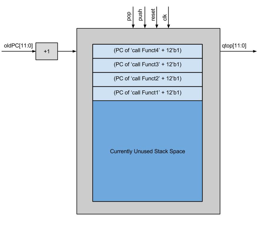
Return Address Stack Module Diagram
When the ret instruction is encountered the decoder simply indicates sets the value of popRAS high. This indicates to pop the top of the RAS and move it into pcnext. Because the RAS automatically incremented the PC as we pushed it, we only need to pop the value into pcnext, the CPU will jump to right after the original function call, and the program can proceed as normal. No other operations are required, because the stack pointer will increment as necessary to point to the next return address, or to the top of the stack.
Testing
During development, I had many errors with the hardware RAS. Either it was not returning properly, or it was returning to a garbage memory address, or jumping to the same location repeatedly, so I wrote a test bench to test just the module. This test bench tried to emulate the conditions that the RAS would see under ordinary conditions in the processor. Specifically, this test case reset the module, and executed a sequence of function calls and returns, and made sure that the correct PCs (including the increment) were popped in the correct order. I attempted to emulate the delay from the decoder by changing the commands in the middle of the cycle instead of right at the beginning to ensure proper operation. I was able to use the waveform display to debug my issues with the RAS, and then proceeded to connect it in the Pancake and run test code.
I wrote a simple test file called rastset.cmp and slowed down the clock rate on the Pancake to 1Hz to be able to better see the PC changing as functions were called and the RAS was popped. This test function had similar behavior to the test bench, but it's purpose was to ensure that he decoder was properly passing signals to the RAS, and the pcnext logic was properly using the output value.
Multiply and Accumulate Vector Structure
Design
It is possible to perform a multiply and accumulate operation on a pair of vectors entirely in software. However, the Syrup method of handling array indexing is very slow, and thus it is not suitable for performing any kinds of high performance signal processing tasks. I successfully enabled an efficient multiply and accumulate, as well as opened up the potential for other additional vector operations in Syrup by implemented a separate vector state machine within the regular CPU state machine.
In general, a multiply and accumulate operation first sets an accumulate value to 0, then for each element in two vectors, multiplies the elements from the two vectors at each index, and then adds the result of the multiplication to an accumulate variable. This relatively simple to describe at a high level, but the existing way Syrup processed this was very slow. It appears relatively simple to access vector indices when writing Syrup code, but the the compiler generates large blocks of code. First, the base address of the vector is pushed, followed by the offset value (which has to come from a variable as per the specs of the compiler and not just a constant), the correct index is computed, and the value can be read or written. Loading a value within a vector takes 4 total instructions, but storing a value at an index takes 6. When this is coupled with the loop overhead of 6 instructions and the need to first execute a push or pushi on the value that needs to be stored, any vector accesses are incredibly slow.
One of the biggest reasons why this structure has very poor performance is because it does not assume any structure of the memory access or loop. On every iteration, the loop bounds are checked and a brand new memory address is calculated, even though the accesses are sequential. Instead of having to compute the base address plus the offset on each loop iteration, it is much more efficient to store a base register once and keep incrementing the base address on every cycle so long as the CPU is in the middle of processing a vector. This is a valid access pattern for vectors because we know that the multiply and accumulate operation is going to require incrementing the addresses once per access.
Thus the task at hand was to design a way to process vector elements together one at a time in hardware with minimal hardware intervention. The easiest way to optimize vector operations was to fix the way that vectors were indexed to exploit the sequential access pattern. Instead of attempting to calculate a new address each time, I added two additional registers for the addresses of the vectors to be operating on. The way vectors are stored in memory by the compiler is that the 0th element of the vector is located at the base address, and all further elements increase in memory address after that. This memory pattern was very conducive to adding address registers because the base register never needs to be stored after the first access, and each element is stored in sequential addresses. Provided there was sufficient way to indicate the end of an array (which is easiest to do in software) then efficiently accessing array elements would simply be a matter of letting the CPU that it needs to fetch sequential addresses for a certain amount of time, then going back to fetching regular instructions. Similarly, it is not necessary to include the accumulate value as a general purpose variable - it will only be used in vector operations, each vector operation should clear the value prior to writing to it. Therefore, it made sense to also include specific hardware to clear or accumulate to this value instead of having to access data memory and take up a RAM port on every cycle.
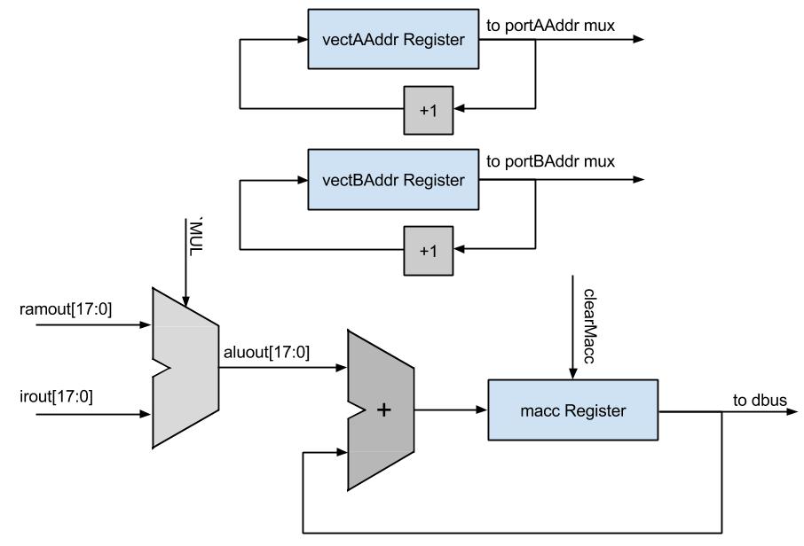
Multiply and Accumulate High Level Diagram
When the macc instruction is first encountered, the CPU is put into a sub-state machine within the regular CPU state machine that enables the sequential memory address fetching. As it enters this state machine, a count register is also loaded with the vector length from the instruction so that the state machine can terminate at some point and transition back to regular CPU operation. There are two initialization states and two steady states for this state machine. In the first state, INITA, the base address of the first vector is popped off of the regular data stack into a new register that holds the address of the next element of the first vector to be accessed. Additionally, the register that holds the accumulation value, which is just called macc, is cleared. Lastly, the length of the vector to calculate is stored into a register in the state machine. The state machine then transitions to the INITB state. In this state, the data stack is popped again into an analogous register that holds the current address of the second vector. The CPU then transitions to the steady state behavior of the macc instruction, which begins with the state called VECTA.
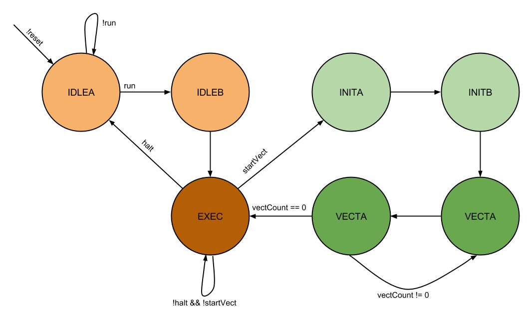
Pancake CPU State Machine
It is important to note that while the CPU is in this sub state machine, the muxes that select what the inputs to the address ports on the dual ported RAM select the vector address registers, instead of selecting the address bus and the pcnext as the inputs, which are selected during ordinary operation of the CPU. Loading a new vector address register means that on the following cycle, the correct vector element will appear on the output of the RAM on the following cycle as long as the CPU is in the vector processing state. Therefore, when the addresses are loaded into the respective registers during INITA and INITB and the state machine first arrives at the VECTA state, the outputs of the RAM on both ports will contain the values at the addresses from the previous cycle. The future iterations of returning to VECTA will also require that the memory addresses are correct at least the cycle before, so that VECTA can perform the actual accumulation. The VECTA state also decrements the vector length register so that the VECTB state knows when to exit the vector state machine.
When the CPU is in the VECTA state, the decoder indicates to accumulate the output of the ALU into the accumulate register (which was cleared during initialization), and increment the addresses of the two vectors. In all of the vector states, the ALU is always multiplying the output values from the dual ported RAM together. The ALU function input is selected as the multiply function while in the vector states and the inputs are the RAM outputs. Updating the accumulate value is in a sequential logic block, so the correct value will not appear until the next cycle. The two vector registers are incremented regardless of if the last element is already being proceeded to reduce decoder logic - either the increment was necessary to process more elements or the next time a macc instruction is called the addresses will be reset anyway. This was more efficient than generating logic to determine whether or not to increment the addresses.
At this point, the correct addresses should be loaded up into the correct locations to be able to compute another iteration of the macc on the next cycle, as the addresses should have incremented. However, a fourth state, VECTB, is needed to get the timing on the address registers correct. Therefore the VECTA state always transitions to the VECTB state, and the VECTB state contains the logic for checking the vectDone flag from the state machine and pushing the resulting macc to the data stack if necessary. The vectDone flag is set by the state machine if the length register (which is decremented by VECTA) is 0 and the state machine is in the VECTB state. The VECTB state doesn't compute anything or update any registers, but I was not able to obtain proper macc operation without this buffer state, so it remained in the final implementation. Furthermore, it would not have been possible to speed up macc any more past eliminating the VECTB cycle, aside from increasing memory bandwidth.
Testing
Debugging and testing the macc instruction was very difficult. All of the registers are internal state and don't reflect any visual output, so I had to use the red and green LEDs and slow down the clock to be able to see change on a cycle by cycle basis. Ordinarily, developing proper CPU hardware involves using a large set of test benches and waveform analysis programs. Given that the Pancake CPU is specific to ECE 5760 and no other extensive redesign work had happened before, there are no existing tools for debugging. It would have likely taken me the majority of the allotted development time just to develop a testing framework, which would have left no time for design or gathering meaningful results. Although it is not a very elegant solution, my primary method of debugging was to slow the clock down to 1Hz, and output some relevant data on the LEDS (like pcout and pcnext, or the top of the RAS) along with some state data like the CPU state and the slowed clock. I then developed some test programs, ran these programs on the slowed down Pancake, and took videos of the LEDs changing on my cell phone to see the state and registers change over time. This was a very crude debugging structure, but it allowed me to save the results of different programs running over time and be able to analyze each cycle individually as needed.
The process of running test programs and video recording the results was time consuming, but it was effective. I was successfully able to debug the extensions and also add hardware to calculate the time it took to run certain programs. I borrowed a hardware timer structure from one of my previous ECE 5760 lab assignments. The structure had a timer that continually counted up on every clock cycle until the CPU sent a signal indicating that the computation had finished computationDone. The time was displayed on the 8 seven segment displays on the DE2 board, and the timer was able to achieve timing down to one ten millionth of a second. This structure allowed me to determine exactly how long programs were running and be able to see the speedup of new programs over old programs.
A Note on Decoder Updates
One important decoder change that was not previously mentioned was the change to the load and store instructions. As will be discussed in the following section, the load and store operations in the ISA were changed to be contained within the same opcode. These instructions use the lower order bits to differentiate between a load and a store. The decoder needed to be slightly changed to reflect this ISA change, but it posed no significant design challenges.
ISA and Compiler Modifications top
To run write and run software on Pancake, the programmer can either manually write Pancake assembly, or can use the high level language called Syrup, and use the associated compiler written in MATLAB. Either the manually written assembly or the compiler generated file has to be in a specific file format called a Memory Image File (.mif), which is used to initialize the M4K memory used on the Pancake, and holds all of the instructions and data. Both the compiler and language syntax can be found at Bruce Land's page on the Pancake CPU, so I will not go into all of the details of the language. Instead, I will just discuss the relevant aspects of the compiler and the changes made for this project.
Adding macc and hardware RAS support required implementing 3 additional instructions. Unfortunately, the instruction width and memory address space only supports an op code length of 4 bits, so there were not enough op codes to simply add in my 3 instructions while also leaving room in the ISA for Roland Krieger's Pancake Interrupt Support (a related ECE 5760 project). The ability to easily interface these projects to create an even more powerful Pancake was more important than maintaining backwards compatibility with existing pancake code. In addition to adding the ret, call, and macc instructions, I also changed the definitions of load and store. This requires recompiling of all previous pancake code, but this seemed to be worth the tremendous performance speedup of the call/ret structure, the new vector support, and the potential to also add in interrupts.
call and ret
As previously mentioned, the previous function call and return structure was very slow. A function call was detected by parsing a token in the Syrup code that matched one of the declared function names. The compiler then generated code to access the software RAS, and push the current PC + an offset to jump to the correct location. When changing the function structure, I used the existing method of determining when a function was called and how to link up the function symbol value. Only changing the compiler and not the linker saved a considerable amount of development effort.
ISA Modifications
ret instruction
| opcode | Lower Order 12 Bits |
|---|---|
| 'b' | Unused |
call instruction
| opcode | Lower Order 12 Bits |
|---|---|
| 'c' | Function Entry Point |
Compiler Modifications
Opcodes b and c were unused, so I first only had to add additional entries to the opcode table. The entry for ret in the table indicates that the opcode is 'b' and that there are no arguments, thus there is no linker work to be performed for a ret. The call entry has an opcode of 'c', but also indicates that there is an argument which is an unsigned 12-bit integer. This argument is the symbol value of the function to jump to, which gets properly linked in the linker, which runs at the end of the MATLAB compiler. As the compiler parses the Syrup code and detects that the next token was a function call (as indicated by a token match in the symbol table and the correct symbol type), the compiler generates a single line of code - the instruction name for this instruction is 'call', and the symbol value is the function to jump to. The linker later parses the instruction name and the symbol value into an instruction, which gets written to the .mif file.
macc
ISA Modifications
macc instruction
| opcode | Lower Order 12 Bits |
|---|---|
| '8' | Vector Length to Compute |
Compiler Modifications
The hardware changes for the macc instruction were much more difficult than the compiler modifications. Adding macc support only required three changes in the compiler. First, I enabled a 'vector' symbol type within the 'variable' symbol type to allow pushing vector addresses. A variable is declared as a vector if the name 'vector' appears after the variable name declaration followed by a vector length. This is still stored in memory in the same way as any other variable, and still allows vectors to be stored as regular variables. Allowing both types provides legacy support for the old vector style so that existing pancake code does not have to be rewritten, only recompiled. Regardless of the vector type, a store to a vector element was not changed - first the base address gets pushed, followed by the offset, the effective address is computed, and the value can be stored. However, when a vector is pushed to the stack to be used in a vector operation, the base address of the vector is pushed instead of the value at the first element in the vector. This enables the hardware to store the vector address in an vector address register to avoid having to push the base address every cycle. This functionality was achieved in the compiler by checking the symbol type of a token in the Syrup code parsing, and if it was a vector symbol, then push the base address. If the macc is intendended to be run over some subset of the vector that doesn't start at the beginning, the programmer has to generate code to add to the base address pushed by the compiler. The hardware will interpret the value from the top of the data stack as a base adress, so if the programmer modifies the top of the data stack to point the "base address" to be some place in the middle of the vector, then the hardware will start fecthing vector values at that offset and operate normally.
The entry in the opcode table for macc has the opcode of 8 and indicates that there is a 12-bit unsigned int as an argument, which makes up the vector length. Due to limited development time, the macc instruction can currently only be used as an assembler directive in the Syrup code as opposed to a regular keyword, such as if or while. Assembler directives specify the name of an instruction that is to be inserted, followed by a dot ('.'), followed by the argument, if any. In this case, the argument is the length of the macc to perform, and the argument can either be specified as a constant literal or a defined constant. A defined constant is translated from a name to a value in the linker. Because the macc instruction was only implemented as an assembler directive and not a Syrup token, no additional compiler code was necessary - all compiler code for handling assembly written in the middle of Syrup code already existed, I just I had to modify the opcode table to recognize the macc instruction properly. As with all other aspects of pancake, there is no protection on any data, so it is up to the user to make sure that macc is being used properly. To avoid memory corruption, make sure that the vector base addresses are pushed to the stack before the macc instruction is called, and make sure that the macc length specified in the instruction matches the vector length specified in the variable declaration.
The last piece of the compiler that had to be changed for the macc instruction was to change the opcode entry for the st (store) instruction. This instruction was previously opcode 8, but the new macc uses this opcode, so both load and store share opcode 7. The difference between these two instructions is now in the second most significant 4 bits of the instruction. A hex value of 0 in those bits indicates a load, and a hex value of 1 in those bits indicates a store. This is a similar instruction structure used by the ALU functions, which all share a common opcode but have different identifiers in the remainder of the instruction.
Results top
Summary of Results
The hardware extensions to the Pancake CPU provided very good results. The hardware implementation of the RAS drastically reduces the number of cycles it takes to execute function calls and returns, while the new macc instruction makes high performance signal processing possible. Due to the nature of this project, there are no final images or videos to display. However, I have included a set of tables and figures below which quantify the performance improvement over the old Pancake CPU and compiler.
call and ret Tests
First, a set of 20 test programs were run to determine the speed of execution of the hardware and the software RAS. Using the timer system that was implemented, I was able to get precise execution times of the hardware and software implementations, as well as the execution time speedup for the new implementation. There were no existing benchmarks for the Pancake CPU, so instead I wrote a test case that sets up four nested loops of length 1024, and on each loop I called a certain number of function. These nested loops were included because only running a test program of function calls would not be an accurate representation of ordinary programs. Most programs do not run large nested loops, but I wanted to insert a big block of slow code with some function calls to demonstrate how much effect function call speedup could have on a program To simulate the fact that some programs have more function calls than others, I ran the test program 10 different ways, each with a different number of function calls. To extend the number of function calls, I adapted the RAS test program to call additional functions. Below is a table of the results of the test cases. I ran the test program with 1,2,3,4,5,6,7,8,9, or 10 function calls on each loop on both the hardware and software implementation, and calculated the speedup for each test program. The results are found below.
| # of Function Calls | Execution Time on Old ISA | Execution Time on New ISA | Speed Up |
|---|---|---|---|
| 1 | .0012666 sec | .0009871 sec | 22.1% |
| 2 | .0015851 sec | .0010244 sec | 35.4% |
| 3 | .0018996 sec | .0010616 sec | 44.1% |
| 4 | .0022161 sec | .0010989 sec | 50.4% |
| 5 | .0025327 sec | .0011360 sec | 55.1% |
| 6 | .0028491 sec | .0011733 sec | 58.8% |
| 7 | .0031657 sec | .0012106 sec | 61.8% |
| 8 | .0034821 sec | .0012478 sec | 64.2% |
| 9 | .0037987 sec | .0012850 sec | 66.2% |
| 10 | .0041152 sec | .0013222 sec | 67.9% |
The standalone numerical results may be difficult to understand, so I also plotted the execution times and speedups. The plots are found below.
Execution Times
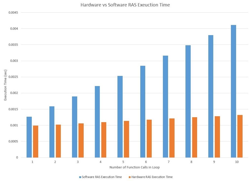
Execution time of test programs for hardware and software RAS
It is clear to see how the hardware implementation of the return address stack drastically reduces execution time as compared to the software implementation. Both execution times increase linearly for increasing number of function calls. The scaling factor for the software implementation is clearly much larger than the scaling factor for the hardware implementation. Even for a single function call where the loop overhead accounts for most of the code execution, the difference in performance is very apparent.
Percent Speedup
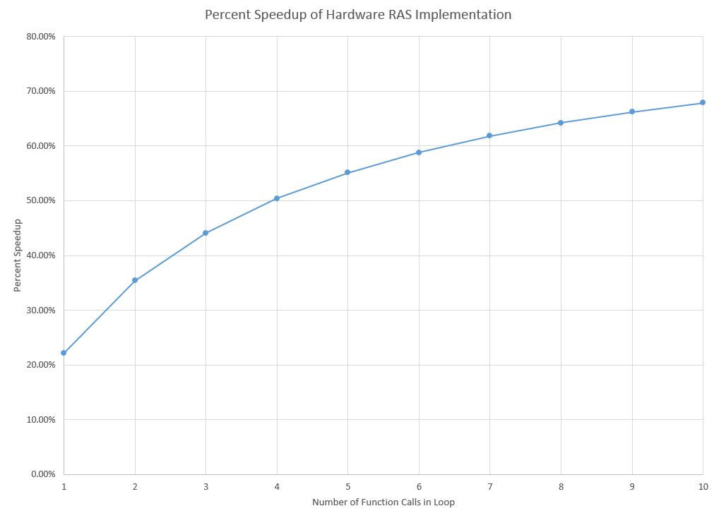
Percent speedup for test programs using hardware vs software RAS
This plot demonstrates another expected, but important result. Speeding up function calls can not make the entire program execute in 0 time. Speeding up function calls can only make function calls faster - the part of the program that executes ordinary code can not be made any faster than it already executes, because this is a single cycle CPU. The percent speedup results indicate that the percentage speedup asymptotes as the number of function calls increase. Although I can't actually simulate for infinity function calls, but I ran the test program on the hardware and software RAS implementations with 100 function calls. The software implementation took .0326010 seconds, while the hardware test took .0046735 seconds, which is a speedup of 85.7%. This is approaching the expected theoretical bounds of speedup of 88.2%, which is the ratio of number of call/ret instructions to number of instructions needed for a function call and return in the old structure (2/17). No matter how function-intensive the program is, performance speedup can never get any better than that.
That being said, the speedup for ordinary numbers of function calls (e.g. 1 to 10) is very impressive. The new call and ret instructions perform better for any number of function calls. For the test program that only calls a function in the middle of loop overhead for four loops, the performance increase is over 20%, and gets up to a speedup of 67.9% for 10 function calls. As the ratio of function calls to other code increases in a program, so does the performance speedup as a result of the new function call and return structure. Clearly, this hardware improvement will cause all existing Syrup code that calls any functions to execute faster regardless of the programmer being aware of this optimization.
macc Tests
In contrast to the call and ret tests, I tested just the macc performance by itself. The rationale behind this was that when a macc is running, it is generally not in the middle of other general purpose code. When the Pancake is processing signals, that is the only work that it is doing, so it isn't necessary to run test cases where the Pancake executes macc code as well as other code involve loops, functions, etc. I chose test vector lengths of 5 and 10 because I wanted data points where the hardware macc overhead can be a considerable number of the execution cycles, and I chose vector lengths of 32, 64, and 128 because they are very likely FIR filter lengths that the Pancake can be used to calculate. It is also worth considering is the overhead to load data into the vectors to process. I ran some test cases that have the vector initialization and the macc and some without the initialization. The macc-only test demonstrate the steady state signal processing capabilities, so they are the more relevant results. In total, there are 4 sets of test cases for each of the 6 different vector lengths: test cases with hardware or software macc, and test cases with or without initialization. The results can be found in the two tables and their associated plots below - one table contains the results without initialization code, and one contains the results with initialization code.
| Vector Length | Software Execution Time | Hardware Execution Time | Speed Up |
|---|---|---|---|
| 5 | .0000048 sec | .0000034 sec | 29.2% |
| 10 | .0000091 sec | .0000061 sec | 33.0% |
| 32 | .0000283 sec | .0000172 sec | 39.2% |
| 64 | .0000562 sec | .0000340 sec | 39.5% |
| 128 | .0001121 sec | .0000679 sec | 39.5% |
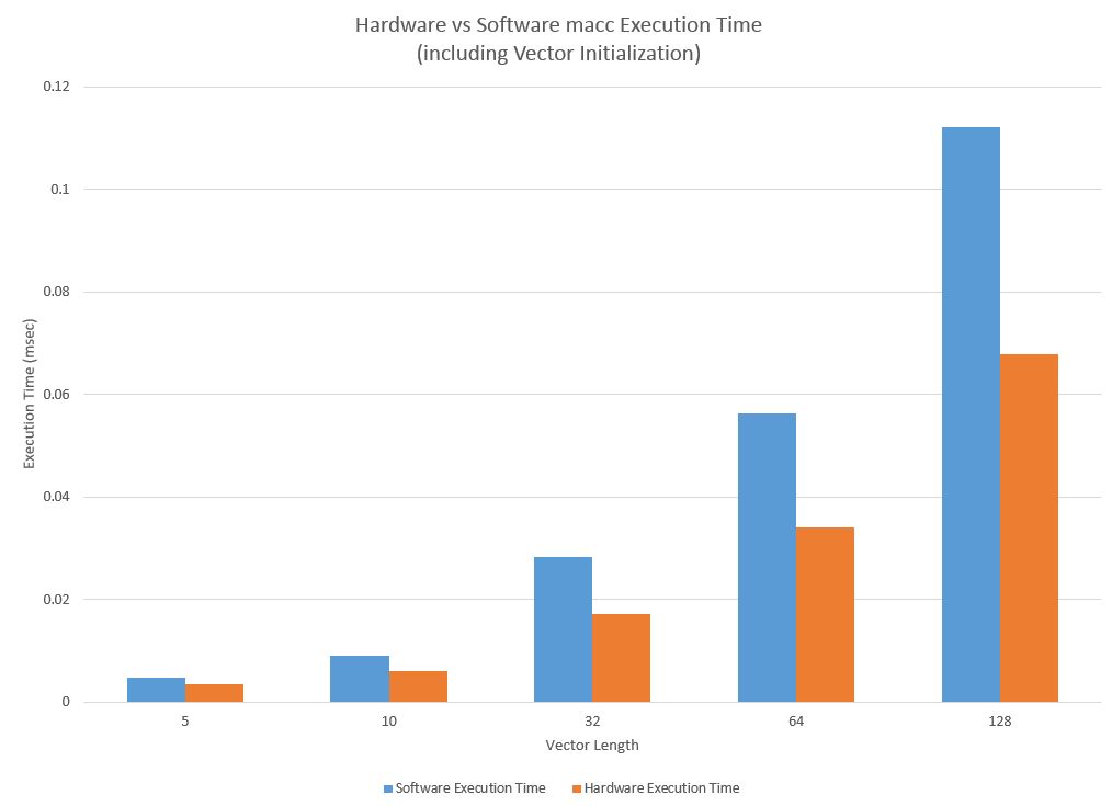
Execution time of test programs for hardware and software macc and initialization code
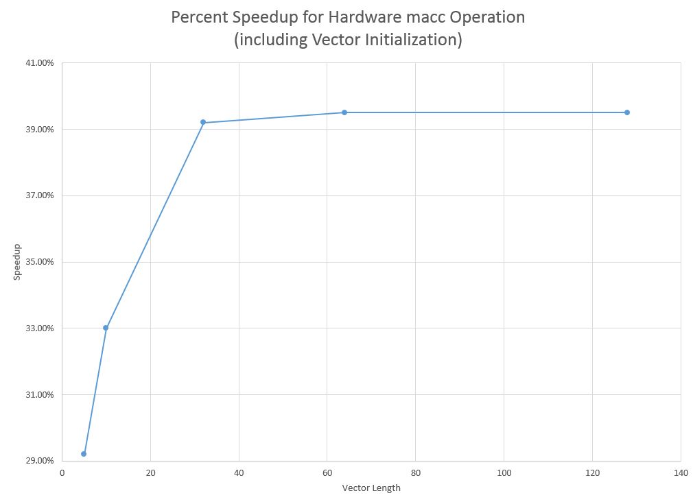
Percent speedup for test programs using hardware vs software macc and initialization code
As the length of the vector increases, so does the amount of vector initialization code that must be executed. The maximum possible speedup is limited by this initialization code, but the speedup quickly reaches this value of 39.5% even for a relatively short vector operation.
| Vector Length | Software Execution Time | Hardware Execution Time | Speed Up |
|---|---|---|---|
| 5 | .0000022 sec | .0000004 sec | 81.8% |
| 10 | .0000041 sec | .0000006 sec | 85.4% |
| 32 | .0000125 sec | .0000014 sec | 88.8% |
| 64 | .0000247 sec | .0000025 sec | 89.9% |
| 128 | .0000491 sec | .0000049 sec | 90.0% |
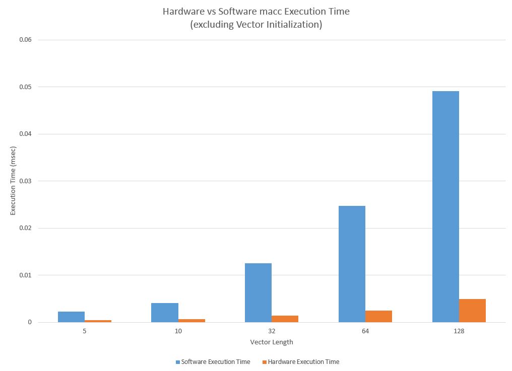
Execution time of test programs for hardware and software macc without initialization code
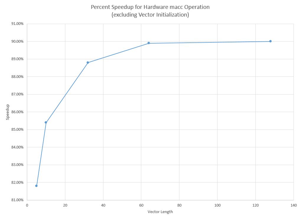
Percent speedup for test programs using hardware vs software macc without initialization code
The macc test program running without the initialization code completes in so few cycles, that the results may not be accurate enough for proper analysis. However, we can still detect trends well enough for basic analysis. Clearly, the execution time for vectors increases exponentially as the vector length increases exponentially, and the software implementation increases at a greater exponential. There are not enough accurate data points to try and determine the exact proportionality constants, but it is clear that hardware is significantly faster. As can be seen from the speedup chart, the speedup of the hardware implementation quickly approaches 90%, which is very good. For a vector length of 5, the speedup is not as high (although over 80% speedup is quite noteable), but that is likely due to the inaccuracy in data measurement and the overhead of pushing vector addresses and basic initialization of the CPU and code than a reflection of the macc algorithm.
The hardware macc operation demonstrated spectacular speedups over the the software implementation. The speedups were tremendous across the the range of test cases, but one of the most important result from these test cases is that for a length 128 vector, which is a typical FIR filter length for audio signals, this version of Pancake can perform 1/(.0000049) macc operations per second, which is just over 204000 operations per second, which is more than four times faster than the rate needed to process audio signals from CDs. Given that this vector structure can process signals four times faster than audio rate, this opens the door for a range of possibilities. The most basic application of this could be running 4 different filters on the same audio signal in one sample window, but there are many other potential applications.
Shortcomings
One shortcoming of this design is that after these Pancake modifications, the reset behavior no longer seems to work. On active low reset, the CPU should transition to the IDLEA state, which should reset the PC to 0, it should then transition to the IDLEB state, where the PC of 0 gets loaded into the instruction register, and finally moves to the EXEC state where it can start executing instructions. However, for some reason when the new Pancake CPU is reset, it does not fall through this set of states, so the PC is not reset back to 0, and so the CPU does not execute proper code. I did not change this section of the state machine or modify the reset behavior, so I have no idea why this aspect of execution is no longer working. When I was developing the RAS, I distinctly remember the reset behavior working correctly, so I'm not sure what could have gone wrong. It is possible that my compiler optimized the reset logic out of the CPU, whereas the full lab compilers did not. Either way, this issue needs to be investigated and resolved before this iteration of the Pancake can become the full ECE5760 version that students use for development.
Another shortcoming of this design is that it doesn't have a method for interacting with signals on input ports to perform vector operations on. Given that one very likely application of the macc instruction is to process some real time signals, the existing architecture requires that a vector of data needs to be read in from the input ports into memory, and then a macc operation can be called, which is significantly slower than being able to process directly from the input port.
Accuracy of Results
In order to collect timing results from test programs, I adopted a scheme of using the seven segment displays on the DE2 board to display a count of the time elapsed between reset and when the CPU output a signal indicating that it finished executing the program. Unfortunately, there are only 8 seven segment displays on the board, which means that it is only possible to 8 digits of precision. It is necessary to start at the ones digit to be able to run long test programs and capture the highest order digit. That leaves only 7 remaining digits of decimal, which gives an accuracy of 100ns, but the clock runs with a period of around 20ns, so it is only possible to get within 5 cycles of the true clock time. Although it would be best to be able to count individual cycles, but having a maximum error of 5 cycles is acceptable, especially given that I expect some test programs to take up to a few seconds, which is 7 order of magnitude higher so the percent error will be very low. It is important to note that during these tests, I used the default CLOCK_50 input from the DE2 board instead of the phase locked FAST_CLK because I was running into counter accuracy errors when using a 50.4MHz clock instead of a 50MHz clock.
Interfacing with other Pancake Extensions
In the same semester that I developed the RAS and MACC extensions to pancake another student, Roland Krieger, developed interrupt support for the pancake. Ideally, the two sets of extensions should be interfaced easily enough such that it does not take another design project to merge the designs. In the interest of integration, Roland used opcode a for the interrupt instructions, and I used opcodes b, c, 8, and I modified 7. Changing the opcodes is not too difficult because the op codes are defined in a few specific locations in the compiler and the Verilog code, and changing the op codes is a matter of changing the few definitions.
The aspect of integration that will likely prove more difficult is interfacing the state machines. Both him and I modified the CPU state machine in order to achieve our goals. While it may be unlikely, it is possible that an interrupt could occur in the middle of a vector calculation. Special care in integrating the two updated state machines must be taken such that the pancake supports precise interrupts. That is, receiving an interrupt in the middle of a vector instruction should not force the interrupt to wait until after the vector operation is finished, and receiving an interrupt in the middle of a vector operation does not cause corruption of the macc instruction
Usability
Writing software to use the new instructions implemented should not be difficult for anyone with experience with Pancake to understand. The call and ret instructions are completely transparent to the programmer, so using these instructions will not require any new education for the programmer. However, using the macc instruction does require a slight shift in the programming paradigm of pancake, which might be a little more difficult for a programmer to get used to. First, any vector that a programmer wants to use as part of a macc or any future vector instruction needs to declare the variable as a vector type in the "variable" section of code. Next, due to limited development time, I did not have time to implement macc as a keyword on the compiler, so if a programmer wants to use the instruction, he has to use an assembler command. This would not be too out of the ordinary for a pancake programmer, but the macc instruction comes with the extra complication of requiring the user to push the base addresses of the vectors to the stack before calling the assembly instruction. This is not a good ISA feature, because it exposes the microarchitecture of the Pancake to the programmer. Exposing microarchitecture should be avoided at all costs, and on future revisions the compiler should be able to call macc like a regular function call, and specify and API as opposed to requiring the programmer to use and assembler command.
Unfortunately, due to the limited instruction width of the instructions, there are not many available op codes that can be used. As a result, to allow for the additional instructions, some of the instructions were combined into the same opcode, but used other parts of the instruction to dictate how to process the instruction. The ISA changes to some op codes make it impossible to run old compiled .mif files on the new pancake CPU. However, as the call and ret instructions are transparent, and old code will clearly not have any macc instructions, then running old code on the new machine will simply be a matter of recompiling - no rewriting of the software is necessary.
Conclusions top
Did The Design Meet Expectations?
My extensions to Pancake met my expectations. Initially, I sought to add compiler and hardware support to speed up performance of the Pancake CPU without drastically changing the existing architecture, and I believe that I achieved this to the best of my abilities in the available time frame. The new function call and return structure does not change the syntax of Syrup code, but it changed the Pancake ISA and compiler to execute function calls in a single instruction, instead of 9, and function returns in a single instruction, instead of 8. The multiply and accumulate instruction that was added changes the Pancake architecture slightly to introduce some microcoding and changed both the ISA and the way Syrup code is written. However, this additional complexity comes with the added advantage of processing multiply and accumulates in 2 + 2N cycles which is a tremendous improvement over the old software structure of taking 9 + 18N cycles. This improvement allows the Pancake to multiply and accumulate 128 samples (a typical FIR filter length) well beyond the CD audio signal rate, which improves the range over which the Pancake can provide useful software applications.
Working on this project provided me great experience in developing hardware on an FPGA, understanding compilers, and how to effectively write and modify an ISA. It gave me a great way for me to make practical use of my knowledge of computer architecture in a way that was rewarding for me, taught me new things, and made other more exciting projects possible for future classes of ECE5760.
Did The Design Conform to Standards?
No IEEE standards or other standards were used in this project. I have attached a copy of the ISA to be used with this version of the Pancake CPU so that future students can easily interface with the new design.
Legal and Intellectual Property Considerations
I developed the pancake extensions using code provided by Bruce Land and the ECE 5760 course page. The original Pancake code was developed by K. Nakano, et al., and it was adapted for the DE2 board and ECE 5760 by Bruce Land. I give Bruce Land permission to publish, modify, and reproduce my development work in accordance with all proper Copywrite and Intellectual Property laws.
Ethical Considerations
I conducted all development on this project in an ethical manner. I adapted code for my extensions from the baseline Pancake code, but developed hardware and compiler extensions myself. I discussed some development ideas with Roland Krieger, who was also working on extending the Pancake CPU, and the course staff, but all work and writing is my own.
Future Work
There are several ways that the modified Pancake CPU can be improved, given additional development time. There are a variety of additional instructions and new features that can be implemented on the pancake, so I will just focus on improvements that can be made based on my development. Specifically, I will discuss vector improvements because I have already sped up function calls and returns to a single instruction each, so it is not possible speed them up further.
The macc process can be sped up from 2 + 2N instructions to 1 + N instructions. The first 2 cycles of the macc are required to pop the two vector addresses from the stack. The data stack used in the CPU supports popping two values in one cycle, so it should be possible to decrease the two cycle start up time to a single cycle. Given that it takes a single cycle for values at an address to appear on the output of the memory, it is impossible to entirely eliminate the startup time associated with the macc instruction given the current memory architecture. However, it is also possible to further decrease processing time to 1 + N instructions, which doubles the steady state rate of processing. While in a macc instruction, the CPU is not fetching any more instructions, so the RAM port ordinarily associated with instructions can be used to fetch data twice as fast. If both sets of vector elements could be accessed in the same cycle, each individual set of operations would only take a single cycle as opposed to waiting two cycles for memory. Past this, it is not possible to speed up, because the existing RAM only has two ports, and so we can not fetch more data per cycle. Given additional memory bandwidth, more registers and multiply hardware could be added to compute the macc faster. Unfortunately, the limiting factor on vector operations is memory bandwidth, so it is impossible to compute more than 1 macc iteration per cycle even with more multiply hardware. If Pancake is to be adapted for high performance signal processing, it is possible to add additional specialized M4K block memory to the CPU. This would be a special vector memory with its own .mif file, and would have incredibly wide output bandwidth. The maximum output width on the M4K blocks are 128 bits, and given that 2 ports can be used, it would be posible to get (128*2/16)= 16 16-bit words out of memory each cycle, and so 8 vector elements could be processed at once. This would take considerable development effort to compile two sets of .mif files and manage two separate memories in hardware.
Another way to improve upon my Pancake extensions would be to implement more higher level DSP functions. The architecture can now support vector based instructions that can process elements relatively quickly and increment addresses automatically. macc is the easiest vector operation, but it would not require significantly more effort to perform instructions to efficiently load data into vectors, perform operations such as a vector-vector multiply, or even perform a fixed point macc. Fixed point macc would only require a single instruction change, and another input to ALU instruction mux for determining what function to execute. Vector-vector multiply would require additional latencies in writing back data, because now some of the memory bandwidth has to be taken up by write backs, but the operation could potentially finish in 1 + 2N, or even 1 + 1.5N, with careful use of memory bandwidth. Vector load would not improve the steady state performance of DSP algorithms, but it would speed up the process of loading data into vectors at the expense of additional compiler complexity. Because the Pancake is limited by a data stack size of 16, it is not possible to easily push all data values to the stack and then pop them off sequentially into the proper addresses. Instead, it may be possible to create a new instruction that indicates to the processor that the next N pushi instructions are pushing the values into a vector, instead of on to the data stack. This would likely require a few instructions or cycles of set up time. However, this would be significantly faster than the existing structure, which requires looping (which is slow in Syrup) and array indexing (which is also slow in Syrup).
These are by no means the only available additional extensions to Pancake, and I invite any interested parties to improve upon my designs, or to contact me at cig23@cornell.edu to discuss further improvements.
Acknowledgements top
I would like to acknowledge Bruce Land and the ECE 5760 course staff for their support throughout this project. I would also like to acknowledge K. Nakano, K. Mawakami, K. Shigemoto, Y. Kamada, and Y. Ito for their original development of the Panckake CPU.