Introduction top
In this project, the stack-based cpu known as Pancake was expanded to include some synchronous interrupt operations. This involved changes to the cpu state machine, other parts of cpu hardware, and to the compiler. The cpu was originally designed by Nakano K., et. al., and modified by Bruce Land to include more functionality like function calls and one dimensional arrays. To enable interrupt capability, a module aptly called ‘interruptHardware’ was added to the cpu. This module provides the functionality for an 18-bit timer interrupt, interrupts from KEY[3:1] and an unused interrupt input which could be connected to other hardware for generating interrupts. The cpu state machine was modified to include two extra states for beginning interrupts and ending interrupts. A pancake program resides in a dual-ported M4k RAM block and is accessed with a program counter and an address bus. A program was written to demonstrate that interrupts work. The program uses timer interrupts to draw different lines on the screen and uses push-button interrupts to change the colors of the drawn lines. The program works very well for the most part. Once in a while, pressing a pushbutton will cause the program to reset or freeze.
High Level Design top
Rationale
The rationale for this project is to add interrupts to the simple but useful cpu called Pancake. Such an implementation would simplify projects that require connecting a lot of hardware to the cpu and performing actions when a button is clicked for instance. Having timer interrupts would also solve the problem of setting a flag in hardware and waiting for a handshake from the software when the flag is encountered at a particular line of code. More specifically, in the artillery duel video game in lab2, an interrupt generating timer could be used to determine the time step for solving for solving kinematic equations of the projectile. The buttons could also generate an interrupt to fire the cannon balls.
Logical Structure
The interrupts allowed in this architecture are synchronous. This means that, the interrupt events are checked at the rising edge of the cpu clock. A new module known as ‘interruptHardware’ was added to the existing cpu. This allows five different kinds of interrupts: a periodic timer interrupt, interrupts from KEY[3:1] and an unused interrupt source to which the user can connect some other hardware for triggering interrupts. The most important components of the ‘interruptHardware’ are the interrupt flag register, the gieLocal (interrupt hardware specific global interrupt enable) register, the interrupt mask register, and of course the 18-bit timer. The purpose of the interrupt flag register is to show which interrupt source generated the interrupt. The register gieLocal acts as a global interrupt enable. Basically, when an interrupt occurs, gieLocal is set to ‘0’ so that no other interrupt can occur within the current Interrupt Service Routine. Otherwise, gieLocal is set to 1. For an interrupt to occur, gieLocal has to be enabled by hardware. The register ‘interruptFlags’ is used to calculate the ISR address to jump to when an interrupt occurs. The interrupt vectors are stored in memory locations 12-16 of program memory/ram (right before main). During compile time, the address of the timer ISR would be written in memory location 12 for instance. Thus, the cpu knows exactly where to jump to when a an interrupt occurs. The cpu state machine has 5 states to be explained later: IDLEA, IDLEB, EXEC (execute), INT_BEGIN and INT_END. It was decided that the expansion to the instruction set would only use a value of 4’ha in the 15th to 12th bit of the instruction register to make it easier to interface this project with the other expansions being pursued by Cameron (return address stack and multiply/accumulate).
Relevant Standards
This project uses IEEE standards for Verilog which is ensured by the Quartus compiler.
Hardware Design top
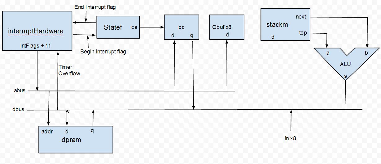
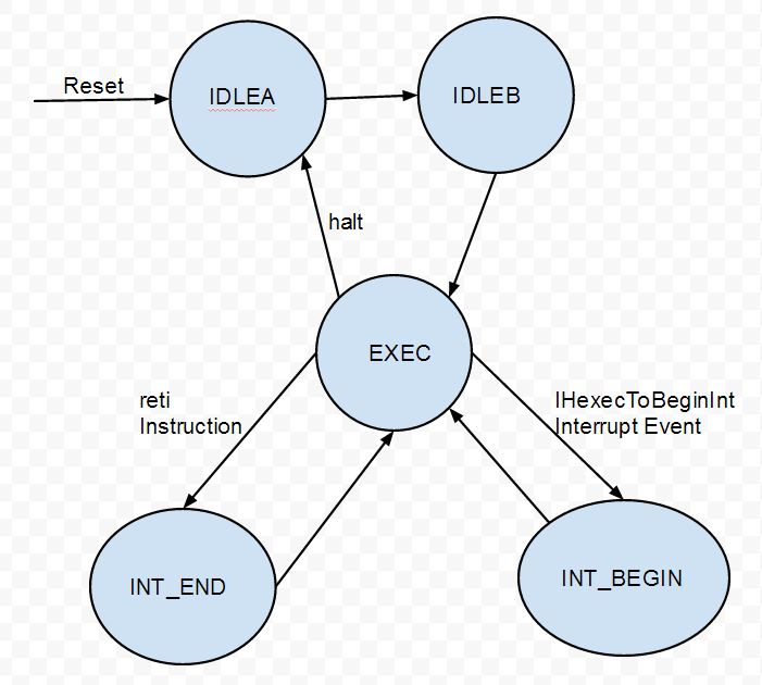
The main parts of the cpu are as follows: state machine (statef), arithmetic/logic unit (alu), the stack (stackm), ram blocks (program memory), instruction decoder and the interrupt hardware. A block diagram of the components is shown in the APPENDIX. State machine: This module (statef) controls the actual state of the cpu. The cpu can be in 1 of 5 possible states: IDLEA, IDLEB, EXEC, INT_BEGIN, and INT_END. The IDLEA state is the default state of the cpu at reset. While in this state, if the run signal input to the cpu is high, the cpu transitions to the IDLEB state. In the current implementation, the input to the minicpu module is a constant 1 thus the IDLEA state always transitions to IDLEB state right after a reset condition. Likewise, the IDLEB state always transitions to the EXEC (execute) state. This is the most important state of the cpu in which all the arithmetic, and I/O functions can occur. The cpu remains in this state until a reset or interrupt event occurs. When an interrupt event occurs, the register ‘SFinsideIntBegin’ is set to logical 1. When this flag is set to 1, pcnext (program counter next) is stored in pcReturnInt. The address in pcReturnInt is the address the program execution returns to at the end of an interrupt. The INT_BEGIN state is the state the cpu transitions to when an interrupt event occurs. The cpu spends one cycle in this state at a time before transitioning back to EXEC to execute the code in the ISR. The purpose of the INT_BEGIN state is just to reset the ‘SFinsideIntBegin’ flag which was set when the interrupt event happened. The purpose of this flag is to cause ‘pcout’ to be set to pcnext so when pcinc (pc increment) is high, pcnext can be set to the right ‘pcout + 1’ value. This flag also sets the address bus to ‘intFlags + 11’ which is the address in RAM where the interrupt vector for the pertinent ISR is located. After the right interrupt vector is selected, the program jumps to the address in that vector and the cpu transitions back into the EXEC state for program execution to continue. Program flow continues until a ‘reti’ instruction is reached. At this point, the flag ‘execToEndInt’ is set to 1, which would cause the cpu to transition to the INT_END state and set the statefExitInt flag to 1. In the INT_END state, the cpu writes the return pc which is stored in pcReturnInt to pcnext. The ‘interruptFlags’ register is set back to 0. Also, ‘gieLocal’ is set to 1 to enable the next interrupt event to be able to happen (It is set to 0 when an interrupt happens to prevent nested interrupts) ALU: The alu is the combinational block responsible for the arithmetic and logic operations. It takes in two 18-bit inputs: a (top of stack) and b (next to top of stack). It also takes as an input a 4-bit op code and outputs an 18-bit result to the data bus. For more information on the operations supported and the general workings of the alu, visit http://people.ece.cornell.edu/land/courses/ece5760/DE2/Stack_cpu.html. Stack: The stack is implemented using dual ported M4K blocks in RAM. Since there are no named registers, all the variables are thrown onto the stack before an operation occurs. The order of variables on the stack is assumed when a particular function is called. There are push and pop, as well as load operations. There are no named registers except top and next (next to top) of stack. Program Memory (dpram): Program memory is also implemented using dual-ported M4K blocks. The first M4k address (addr1) comes from the address bus and the second (addr2) comes from pcnext. The basic operation is pcnext getting the next instruction in dpram and storing it in the instruction register (irout) using the second port. The first port can be used for two functions. If the load flag is set, the data bus writes to memory at the address ‘addr1’. This is useful for modifying variables in memory. The second function is a read function in which, the value in address ‘addr1’ is written to ramout. In general, this allows the transfer of data from memory to the top of the stack (example putting a variable on top of a stack). It also allows the transfer of the interrupt vector into pcnext when an interrupt event occurs. interruptHardware: This module is responsible for detecting interrupt events and setting most of the registers/flags required for interrupts to exist. It has inputs from 3 pushbuttons (KEY[3:1]). It also includes an input called ‘unusedIntIn’ which could be connected to a piece of hardware to generate interrupts. There is also an 18-bit timer which can be used to generate periodic interrupts. The ‘interruptflags’ register is also used by external modules to keep track of which interrupt event occurred. It is a 3-bit register and can have the following values
| Interrupt Flags | Interrupt Event |
|---|---|
| 0 | None |
| 1 | Timer interrupt |
| 2 | Key 1 interrupt |
| 3 | Key 2 interrupt |
| 4 | Key 3 interrupt |
| 5 | Unused interrupt |
The reason why continuous numbers are used instead of powers of 2 is that the former makes it simpler to implement the logic for obtaining the interrupt vectors (simply add 11 to the interruptFlags register). The interruptMask register is a 5-bit register, where a 1 in a particular bit implies the corresponding interrupt is unmasked. From LSB to MSB, the order used is timer interrupt, KEY[1], KEY[2], KEY[3] and unusedInt. In this implementation, all interrupts are unmasked at reset. However, having the registers and implementing them in this module would make it easier for the future extension of unmasking individual interrupts. The register gieReg is used for global interrupt enable. It is enabled at startup and at every point during a program, except within an ISR. The ‘IHexecToBeginInt’ flag is set when an interrupt event occurs to notify external modules about the interrupt event. At the rising edge of the input clock, an edge detection is done on Key[3:1] and a check is made on the timer value to see if interrupt conditions are met. If any of the keys transitions from logic high to logic low, or the timer equals its output compare/overflow value, then an interrupt event occurs. When this happens IHexecToBeginInt flag is set high to notify other modules of this, and gieLocal is cleared so no other interrupt occurs during the ISR. The interruptFlags register is also set to the right value according to the table shown above. Since the cpu changes from the EXEC state to the INT_BEGIN state based on the IHexecToBeginInt flag, the flag is kept high for only one cycle so that the state change happens only once after an interrupt event. This module also takes as input, a ‘returnFromInt’ flag which is set when a ‘reti’ instruction is reached. When this flag is high, the interruptFlags register is reset to 0, and gieLocal is set to 1 to allow the next interrupt to occur. The 18-bit timer defaults to a period of 1ms. However, its value can also be set using the ‘setTimerOverflow’ command in code. When this happens, the value at the top of the stack is written to the counterOverflow register and the timer is reset. Other cpu hardware: In the main minicpu module, a state machine, stack, alu and interruptHardware modules are instantiated. There is also more hardware in this main cpu module. The most obvious of this is the instruction decoder. Given the value in the 18-bit register ‘irout’, the instruction decoder will set a number of flags that enables the cpu to perform load/store instructions, arithmetic and logic instructions, etc. The two MSBs in ‘irout’ are not used and the type of instruction depends on irout[15:12]. For a list of instructions that are decoded, take a look at the (STACK CPU PAGE). A new set of instructions was added to implement interrupts. A new case was added to the case statement for irout[15:12]. It was defined as ‘INT’ and applies when irout[15:12] = 4’ha. At this point, the type of instruction then depends on the value of irout[7:4]. If it’s a 4’h6, then it is a ‘setTimerOverflow’ instruction. If it’s a 4’h1, and irout[3:0]=4’h2, then it is a ‘reti’ instruction. In a ‘reti’ instruction, the flag ‘execToEndInt’ is set to 1 to cause the cpu state machine to transition from the EXEC state to the INT_END state. For a ‘setTimerOverflow’ instruction, the flag timerOvfChanged is set to 1, which would cause a write from the data bus to the timerOvfReg register. This register in turn will be used to set the output compare value for the timer and to reset the timer. The register ‘qtop2dbus’ is set to 1 to enable data transfer from the top of the stack to the data bus. Finally the pcinc flag is set to 1 to enable the program to execute the next line of code. The program counter is controlled using two registers; pcout which is set sequentially and pcnext which is set combinationally. When pcinc is high, pcnext is incremented by 1 (set to pcout+1). When the jump flag is set (on a jump instruction), pcnext is set to irout[11:0]. When the poppc (pop program counter) flag is set, pcnext is set to qtop[11:0]. When the cpu is in the INT_BEGIN state, pcnext is set to the interrupt vector in ramout[11:0]. When the cpu is in the INT_END state, pcnext is set to the value in pcReturnInt, which stores the last pcnext value before the interrupt event occured. The address bus (abus) is set using a number of flags. As the naming suggests, when ir2abus is high, abus is set to irout[11:0]. When qtop2abus is high, abus is set to qtop[11:0], when qnext2abus is high, abus is set to qnext[11:0]. Finally, when the SFinsideIntBegin flag is high (cpu in INT_BEGIN state), abus is set to intFlags + 11. This implies that the interrupt vectors are located at memory locations 12 to 16 of program memory. If none of these flags is high, abus is set to 12-bit ‘don’t cares’. Finally the data bus (dbus) is also set using the flags: ir2dbus, qtop2dbus, alu2dbus, ram2dbus, in2dbus and pushpc. In order, they allow a transfer to the data bus from: sign extended irout, qtop, aluout, ramout, in[irout[2:0]], and pcnext. External Hardware: There are two kinds of external hardware in this project. The first kind is useful for demoing the project and consists of a VGA controller module, an sram mutex for writing to the screen buffer, a color map, a PLL, and a ROM module for characters. The second kind of external hardware is mainly for debugging purposes. It consists of the hexadecimal displays, an external timer, and a slow clock generator. The first kind of hardware is described below: Phase Locked Loop (PLL) This phase locked loop provides the clock inputs for the rest of the system. This module takes in a 27MHz signal from the DE2 board as input and produces the phase locked VGA clock(VGA_CLK), SRAM clock(sram_clk), and the CPU clock (FAST_CLK). The CPU clock is +90 degrees phase shifted from the SRAM clock in order to prevent a race condition on the SRAM controller if the memory switch logic gets to be too large. The VGA clock is set to 25.2 MHz, and the CPU and SRAM clocks are set to 50.4MHz. VGA Controller The default on-board VGA driver was used by instantiating a VGA_Controller module. This module handled the specifics of the VGA protocol such as running the 10-bit DACs to generate pixel colors, as well as handling the vertical and horizontal syncs needed to properly display an image. The VGA module time shared with the minicpu, as explained in the SRAM Access section. The words stored in SRAM are 2 bytes wide, but only the lower byte is used to store pixels so only the lower byte of any SRAM address is read. The pixel byte from sram is an input to the colormap module, which decodes the 8 bit value stored in memory into 3 8-bit values (for R, G, and B), which go to the video DACs. SRAM Access Both the VGA controller and the minicpu need to access the same locations in SRAM. Because the SRAM clock is phase locked and runs twice as fast as the VGA clock,the VGA clock is used as a control signal into the SRAM controller to determine who has access to the SRAM. When the VGA clock is high then the VGA controller has access to SRAM. When the VGA controller has access, it specifies an X and Y coordinate to read from, and sets write enable high (no write). The read byte comes out of SRAM on SRAM_DQ one cycle later. When VGA_CLK is low, then the minicpu has access to SRAM. If the minicpu is requesting a write, then the minicpu sets the address and data registers of the SRAM, as well as setting sram_lb and sram_we high and sram_ub low, which enables writing of just the lower byte of the SRAM word. The write data comes from the minicpu. Color Map The RGB value of the pixel is determined by a color map that is implemented as a logic lookup table. Given an 8-bit index, it produces 10-bit red, green and blue channels. The external debug hardware has two main modules. The first is a counter which basically counts time to the nearest millisecond and displays the value to Hex2, Hex1 and Hex0. The second is a slow clock generator which slows the cpu clock to a period of about 1 Hz for debugging purposes.
A simplified RTL diagram is shown below
The cpu state machine is shown below
Software top
MATLAB compiler
The script compiler_v2.m compiles the Pancake program into the cpu instructions and generates the memory image file which would be used to initialize the RAM block where the program is stored. Two new opcodes were added. The first instruction, ‘reti’, is the last instruction of an ISR. At this instruction, a flag will be set which would initiate the context switch from the ISR back to normal program flow. The second instruction is the ‘setTimerOverflow’ instruction, which makes the output compare value of the timer the value that is at the top of the stack. These two instructions were tested and worked in general. The instruction for a reti is ‘a012’ and the instruction for setting the timer overflow is ‘a060’. The compiler state machine now has a 5th state in addition to the four set by keywords: constant, variable, program, function. The 5th state is entered based on the keyword ‘ISR’. An ISR begins with ‘ISR’ and ends with ‘endISR’. In this state, the compiler checks that the each ISR has a corresponding ‘endISR’. Otherwise, it will give an error and inform the user of the absence of a closing ‘endISR’. This is extremely important because the endISR keyword is translated to the ‘reti’ instruction which enables the cpu to return from interrupts. The ISR name is also checked and has to be one of the following: TIMER, KEY1,KEY2 , KEY3, and UNUSED. If the right name is not specified (case-sensitive), then an error is thrown. Since all interrupts are unmasked at reset (except UNUSED), it is important to have the first four ISR definitions present and empty if not used. Otherwise, program flow would be unpredictable (perhaps reset) when the undefined interrupt occurs. The UNUSED interrupt is masked at reset. Hardware changes would have to be made by the user to connect a new interrupt source to the ‘UNUSED’ interrupt register. The last section of the compiler behaves like a linker as it generates the memory initialization file (mif) that is used to initialize program memory (ram).
Example program
A simple program was written to demonstrate the workings of interrupts. At startup, the program initializes variables, prints a few strings onto the VGA screen, draws a single line across the screen(top left to bottom right), and enters a while(1) loop with a nop. Without interrupts, that would be the end of observable code execution because a nop would be executed forever. However, due to timer interrupts, new lines are drawn on the screen by rotating the initial line about the center of the screen. Furthermore, pressing the push buttons changes the color of the lines that are being drawn. Key[1] sets the line color red, key[2] sets it yellow and key[3] sets it green. The line color changes between two different shades of grey when the endpoints of the line coincide with a corner of the VGA screen. Changing the color makes it easy to determine when the program has crashed. It is possible to set timer overflow value and watch the speed of drawing lines change. However, some issues were noticed with the setTimerOverflow command that are described in the results section.
Results top
Interrupts were tested using the slow clock to observe the pcnext address on the hexadecimal display. The pcnext address changes to the right interrupt vector during an interrupt and restores the original program flow upon returning from an interrupt. However, once in a while, pcnext is observed to change to 0 when an interrupt event occurs. What may be happening is a race condition whereby the value of the address bus doesn’t settle in time for the program counter to receive the right interrupt vector address. It takes 3 cycles after an interrupt event occurs for the cpu to enter the interrupt handler. Following a reti instruction, it takes 3 cycles for the cpu to return to the normal program flow. The test program had the following results. The cpu is able to take periodic timer interrupts and draw lines by rotating the original line about the center. Furthermore, the line color changes when a pushbutton is pressed. However, once in a while, pressing a push button would cause the program to freeze or to reset. Another bug that was noticed has to do with using the ‘setTimerOverflow’ command before or after printing strings. Below a certain threshold of the value that the output compare is set to, the program crashes.
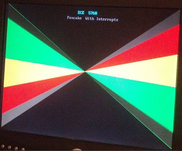
A screenshot of the test program is shown below. The lines are drawn using 5ms timer interrupts and are drawn so close together that they look continuous. The line color was changed to red by pressing key 1, then to yellow by pressing key 2, and finally to green by pressing key 3.
Conclusions top
The task of creating interrupts for a small cpu like Pancake requires modifications to the compiler, to the state machine, and to the instruction set. One challenge is combinational latches. For instance, when the program encounters a ‘sei’ instruction, it saves a 1 into a register (gieCode). This value needs to be latched until another instruction appears that says ‘cli’. However, Quartus gives warnings when such latches are created. Furthermore, when the reset button is hit, the old value of gieCode would still hold at the beginning of the new iteration of the program. As such, I didn’t end up implementing the hardware for allowing the user to set and clear a global interrupt enable flag. One workaround for this could be to have a clocked version of gieCode. Then, at reset, this clocked version would be set to 0 and only allowed to read the value of gieCode after the first instruction in main has been encountered. The compiler would also have to insert a ‘clear interrupt’ instruction as the first line of code to ensure that interrupts are cleared. Similar solutions could be used to implement the hardware for masking and unmasking individual interrupts. The occasional reset of the program during button presses could be caused by interrupts occurring at certain critical sections of program flow, or by race conditions that don’t allow the address bus to be set in time for the interrupt vector to be read from the right address in memory. If the latter is the cause, perhaps introducing an extra cycle of delay between writing to the address bus and reading the interrupt vector might help. It would be useful to slow down the cpu clock to a speed slow enough to send the value of pcnext over serial to a terminal window. Then, if the random failure is associated with particular areas of code (e.g printing a character), then a solution can be developed. In addition to pcnext, some registers like pcinc and pushpc can also be output through serial for debugging. More work could be done to interface this interrupt expansion with the return address stack expansions that were implemented by Cameron Glass. Due to the bugs described above, I would advise that this cpu be used mainly for learning purposes, for instance as the starting point to implement interrupts for the pipelined version of this cpu. Timer interrupts are relatively safer to use than Key interrupts. It would also be worthwhile to implement the suggestions given above to find out what causes the occasional reset-on-interrupt, and to fix it.
Intellectual Property Considerations
The project was adapted from modifications by Bruce Land to an existing cpu by Nakano K. et. al. This cpu is GNU General Public License and is available to the general public for use.
Known Bugs
Occasionally, the cpu resets when a pushbutton is pressed.
When the ‘setTimerOverflow’ macro is used right before or after printing a string to the VGA, it can cause the program to crash.
Tips on Using Pancake With Interrupts
Always remember to have the “ISR ‘name’” and “endISR” directives for all ISRs because all interrupts (except the UNUSED ISR) are unmasked in hardware. The UNUSED ISR need not be commented out.
The timer defaults to a period of 1ms on a 50.4MHz cpu clock. Thus, a software counter could be used to generate a software timer in multiples of 1ms.
Using Notepad++, you could define your own language and color code the keywords to make a visually-appealing text editor. A Notepad xml file has been included for Pancake.
Appendices top
A. References
Cameron Glass' Return Address Stack project
B. Source Code
Acknowledgements top
Thanks to the professor and the TAs for all their help throughout the course.