ECE5760 Final Project
Y
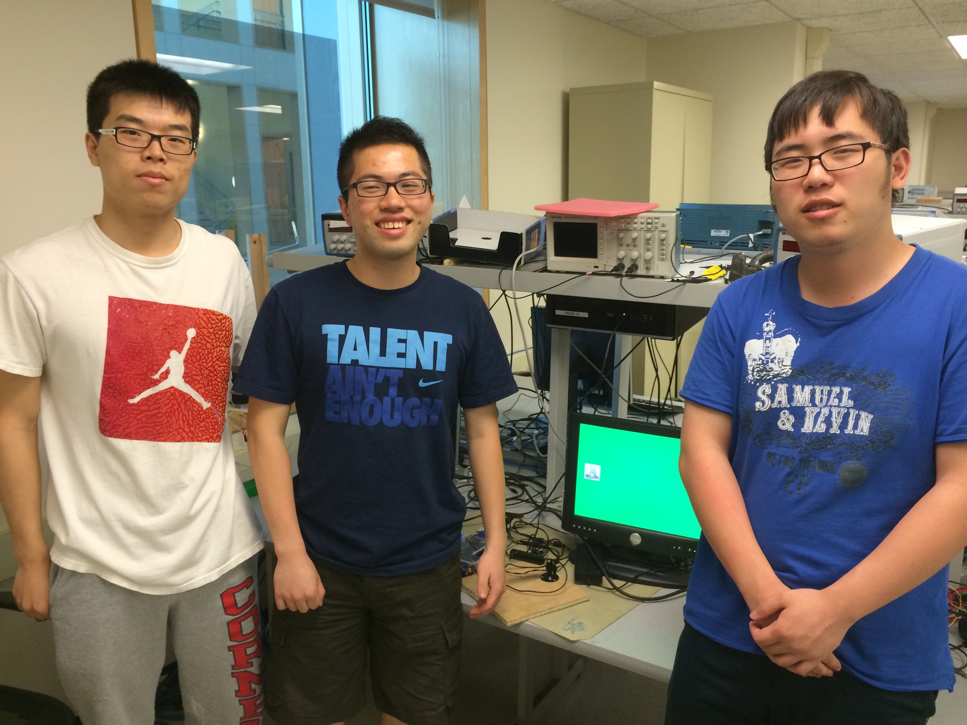
Zequn Huang (zh239), Kang Li (kl694)
Introduction
For the final project of ECE 5760, we design a traditional Whac-A-Mole video game using Altera DE2 board. Instead of hitting the keyboard or touching the screen, we play the game by beating the mole toward the screen using a green racquet. We use a camera to detect the green color. And if the center of the racquet hits the mole, the player will gain one point; on the other hand, if the center of the pad hit Bruce (Sorry, Bruce!), the player will lose five points. If the player reaches 15 points, the level will go up and the speed of the appearance of mole and Bruce will both increase. And when we hit the image or go to the next level, there will be different real-time sound based on the action.
High Level Design
We only use hardware in our design. So the speed of the game can be really fast and the whole system can be pretty stable.
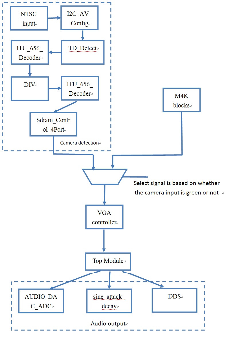
The major module of our design includes Camera detection, VGA display, Audio output, and the Top module.
The camera detection module is the input module in our design. It detects the specific green color in the view and use the center as the collision detection. The reason we choose color green is that it is less likely to be affected by the background comparing to other colors. And the VGA control module and the audio output module is the output module in our design. They are both react to the camera detection module. We connect these modules together in the top module. The brief diagram of our design is as follows:
Hardware Design
Camera Detection
1. NTSC input
We designed this part by modifying the NTSC decoding from Bruce’s sample. The basic NTSC TV inputs are signal “TD_DATA”, “TD_VS” and “TD_HS” from the top module. First of all, the TV decoder module, TD_Detect, checks the stability base on the TV Decoder H_SYNC and TV Decoder V_SYNC. And the output TD_Stable signal feeds in the Reset_delay module in order to generate all kinds of reset delays for transmission timing purpose. Next, the ITU decoder converts the TD_DATA form the camera to YCbCr format. We also have several more modules, YUV422_to_444, YCbCr2RGB, to convert the camera inputs from YCbCr to YUV444 and RGB. Besides these modules, there is a Mirror_Col module, which will mirror the image left to right. In order to output a mirror effect video from camera input, we connected this module in our design. The last module in this sample is the VGA_Ctrl module, which connected the RGB value from the camera inputs to
the RGB of each pixel in the VGA screen.
2. Combine camera inputs with the game interface
In order to combine the camera inputs with the game interface, we modified the connection between Mirror_Col and VGA_Ctrl module from the sample design, and synchronized the clock for NTSC and VGA modules. We took the outputs of the Mirror_Col, Red, Green, Blue. And we checked the value of the RGB component to detect the Green color from the camera since we decided to use a green hammer for our game. The RGB value threshold we set are ((Red<10'd450)&&(Green > 10'd700)&&(Blue < 10'd450)). In this situation, we marked these pixels black by setting all these RBG 10’b0. As the result, we could determine the position of the hammer by looking for black spot. For pixels that have the RGB value out of this range, we just mux the output to the cVGA_RGB, which is the game interface generated from the top module hardware. In this way, we were able to show the position of our green hammer from the camera input to the VGA screen. At
the same time, the VGA also display the game interface at all other pixels that are not marked black.
3. Determine the center of the hammer
Since all VGA points have to go through the VGA_Ctrl module, no matter the camera inputs or the game interface, we chose to modify the VGA_Ctrl module to determine the center of the hammer. In this module, we checked the color of all coming pixels, and if it is black, which means it is part of the hammer, we recorded the maximum and minimum x & y position of all these pixels. And at the end of the screen, we calculated the average x & y value by setting Avg_X <= (Max_X + Min_X)>>1. As the result, we were able to determine the center position of the black spot in the screen. Then we set the center position to white color when we start to draw a new screen. Even though the center position is calculated for the previous screen, it is still ok since the VGA clock ran at 27 MHz. In addition, we got rid of the pixels around the edges because they are problematic with color. Besides those, we kept the original horizontal and
vertical synchronization function in the VGA_Ctrl module.
4. Detect a hit
We generated the flag1img and flag2img when we found the center point of the hammer is in the first or second picture pixels range. These flags are actually the hit flags. However, we could not use it for all these pixels in the VGA screen because we only want to modify the pixels in this range. We generated a new flag, called hit1 or hit2, which is and logic the flag1img with the pixels inside the image x & y range. As the result, we only modified the image pixels when we detected a hit on that image.
VGA display
Since we have two images in our M4K blocks, we can use them to display the mole and Bruce. The amount of possible position of the image is 12 (4 in each row and 3 in each column). And we build a Look-Up-Table to store all the possible position of x and y. We can use the index of the LUT to choose where the image should appear.
We want to generate at most 2 images, no matter they are the moles or Bruce, at one play cycle. And the positions of the two images need to be random. So we need random number generator.
I generate the random binary vector by four 31-bit binary shift registers. The initial states of the four registers are 31'h55555555, 29'h55555555, 31'h66666666, and 29'h66666666, respectively. And We XOR the bit 30 and bit 27 and put the new bit as the least significant bit of the first and the third shift register at every rising edge of the OSC_27 clock, while XOR the bit 28 and bit 26 and put the new bit as the least significant bit of the second and fourth shift register at every rising edge of the OSC_27 clock. These four shift registers are used for determining the position of the images.
The amount of the images is determined by bit x_rand1[30]. If it equals one, there will be two images and if it equals zero, there will be only one image and it has to be the mole. And the indexes of the LUT is calculated by x_rand1%4 and y_rand1%3. If there are two images, the indexes is different by using different shift registers; if there is only one image, the indexes of the two images will be the same by using the same shift register. And in the two images case, if bit x_rand1[4] is one, the second image will be Bruce and if this bit equals zero, the second image will be the mole. And the first image is always the mole. So the possibility of one of the images being Bruce is 50% and if there is only one image, it can only be the mole.
So for VGA display, when it needs to display the mole by reading the correspond flags, the VGA controller will read the two port M4K block which stores the image of the mole. And when the VGA controller needs to display Bruce, the VGA controller will read the one port M4K buffer which contains the image of Bruce.
We use a count to control the timing of the image display. The initial value of the count is 28'h7FFFFFF and the value of the count will decrease based on the level of the game: the higher the level, the smaller the count will be. After the count reaches the setting value, we clear the count and set the new position of the image.
Score mechanism
We determine how to calculate the score in the stage of updating the position. There are several circumstances.
a. There are two images on the screen and both of them are mole. We hit both of them. In this situation, we get 2 points.
b. There is only one image and we hit it; or there are two images, we hit the first one; or there are two images and the second image is the mole and we hit the second one. Under these circumstances, we get one point.
c. There are two images and the second image is Bruce. We hit both of them. We lose 4 points.
d. There are two images and the second image is Bruce and we only hit the second one. So we lose 5 points
All the flags we use in this stage are the same with the flag of last play cycle. Otherwise it will cause synchronization problem.
Audio output
Our audio part is mainly from the course website and it is written by our instructor—Bruce Land. In the audio part, what we can simply control is the wave envelope type and we also use some logic to control when to start. Below are the main modules this audio module calls:
AUDIO_DAC_ADC: This module mainly passes the digital signal to analog signal which will be displayed in a real audio.
Sine_attack_decay: This module is aimed to display the digital synchronize of any given amplitude envelope. Then it will give the sound shape to the AUDIO_DAC_ADC module to generate the sound. In this module what you can change is the amplitude envelope and increment factor which indicates the falling speed of the wave.
Sync_rom: This module mainly generates a look-up table to store the sine wave information so that the sine math can be done just by calling the table.
Above all, you can choose any sounds you want through this audio module and we did choose some different sounds which can match our purpose quite appropriate.
Software Design
In Matlab what we did is to generate two pictures which have the appropriate size so that we can store them in M4K blocks and display them on VGA screen. First picture is the mole, which is used to be attacked. And as described later, this mole will be randomly generated one or two at any position on the screen. The second picture is the fanciest part in our design! We use our instructor—Bruce Land’s head picture (after his permission) as the game Boss that player cannot attack and player will be punished if he/she attacks this picture.
Here we just take the mole’s picture as an example:
1) The first step is to use Matlab to resize the mole’s picture which we found on the internet and then store to a “txt” file with all the pixel information and every pixel we use hex type to store.
2) The next step is to generate the “mif” file which can be read in QuatusII and displayed on the VGA screen. We just cited Bruce Land’s code on the course webpage and changed some sentences so that the “mif” file will be generated in the way we want. For example, the memory size we need to choose ourselves.
3) The last step is to set VGA buffer and choose the size of M4K to store the two pictures, which need to be stored in two different buffers. Then we choose two ports buffer for mole and one port for our instructor. When the state machine need to read either of these two pictures, right port among the three is needed. However, the address will be the same value because they are in different blocks.
4) One thing we need to mention here is that in Matlab any photo type will be stored in three dimensions: red, green and blue. However, the color display in VGA screen will be quite different and has ten bits to display every color. So what we did is to pick three red bits, three green bits and two blue bits in Matlab to combine an eight bits pixel which will also be separated to display on VGA screen. It seems much better than any other methods we have tried but we really think they are not as fancy as the original pictures.
Result
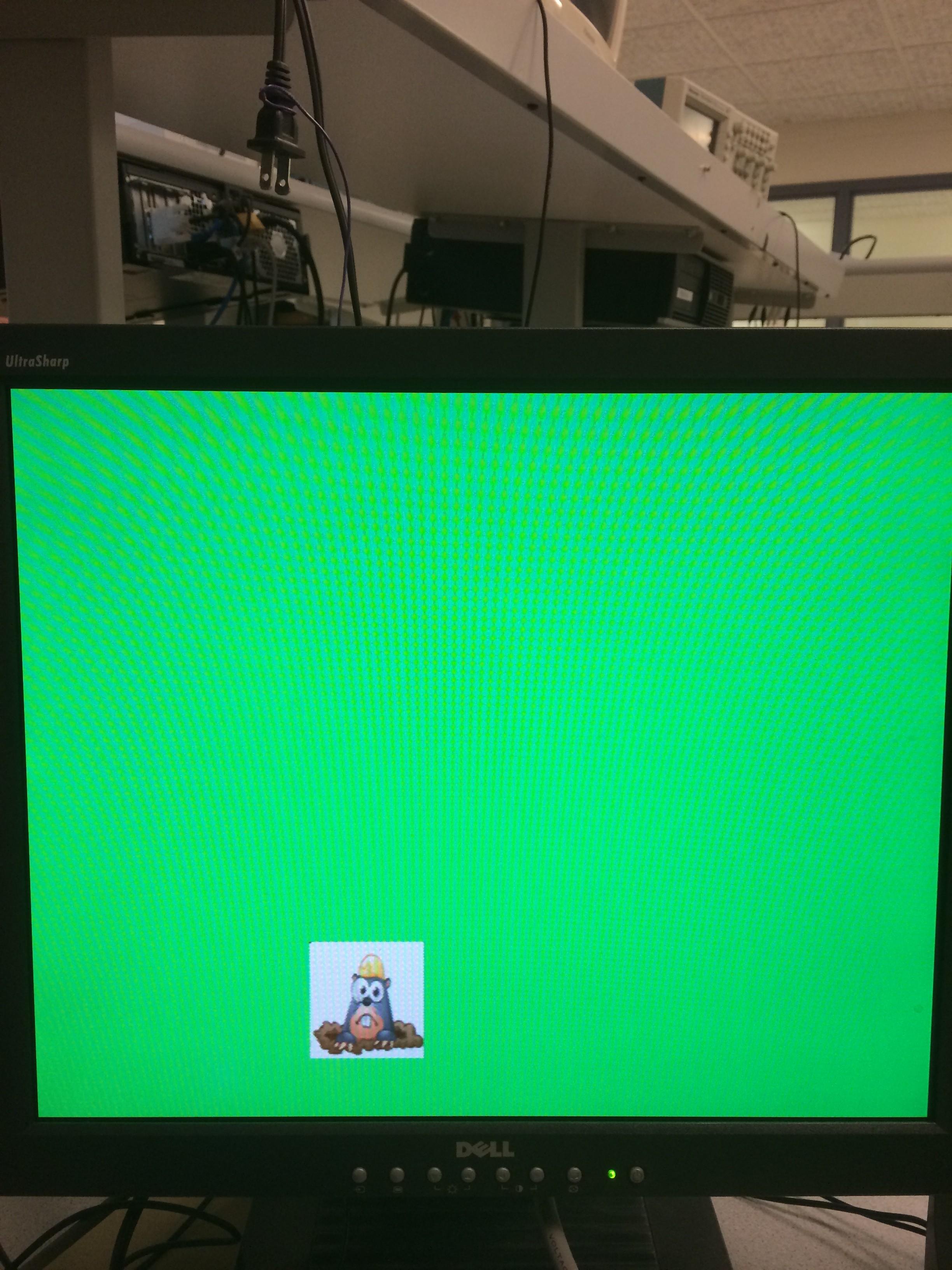
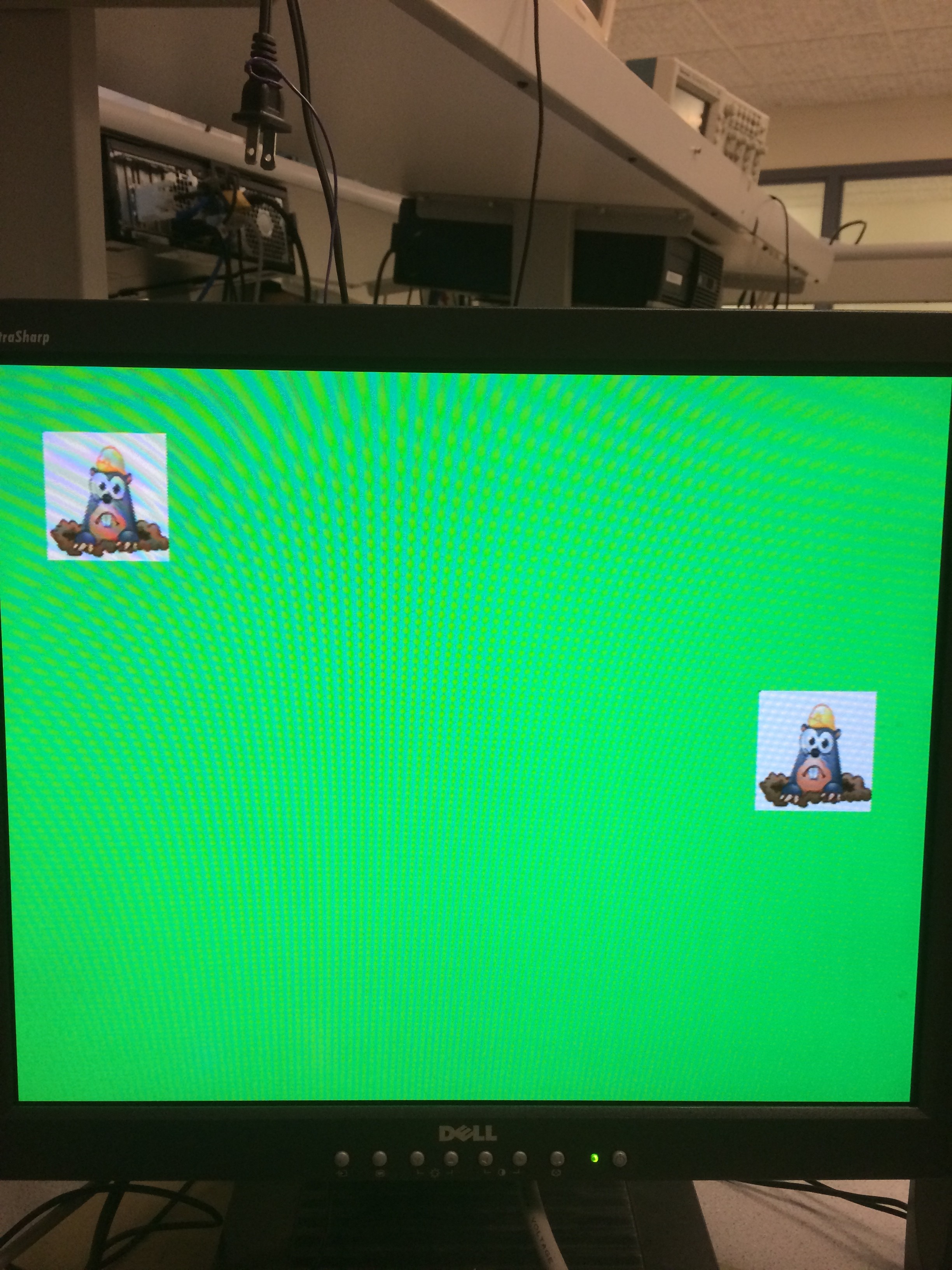
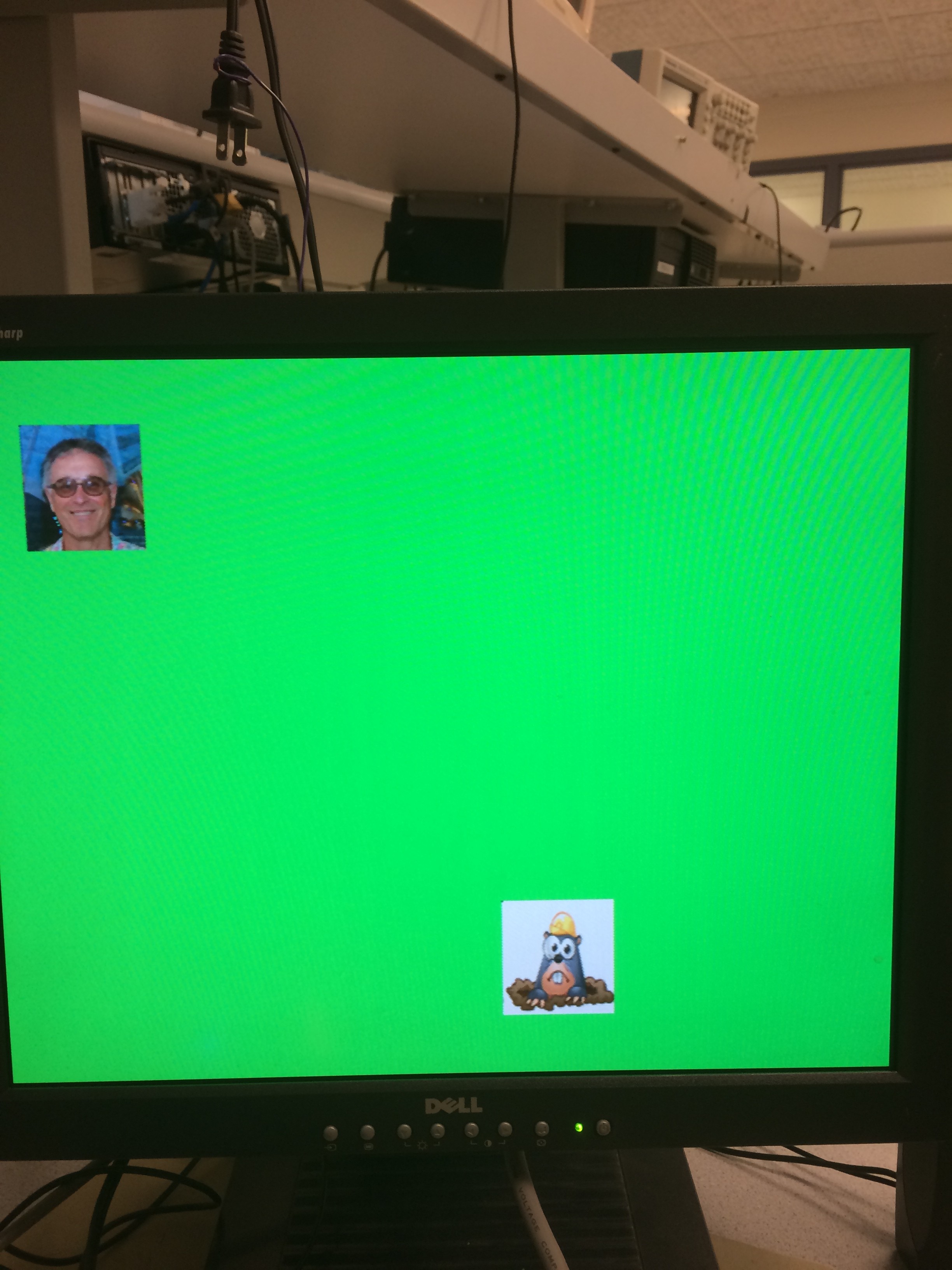
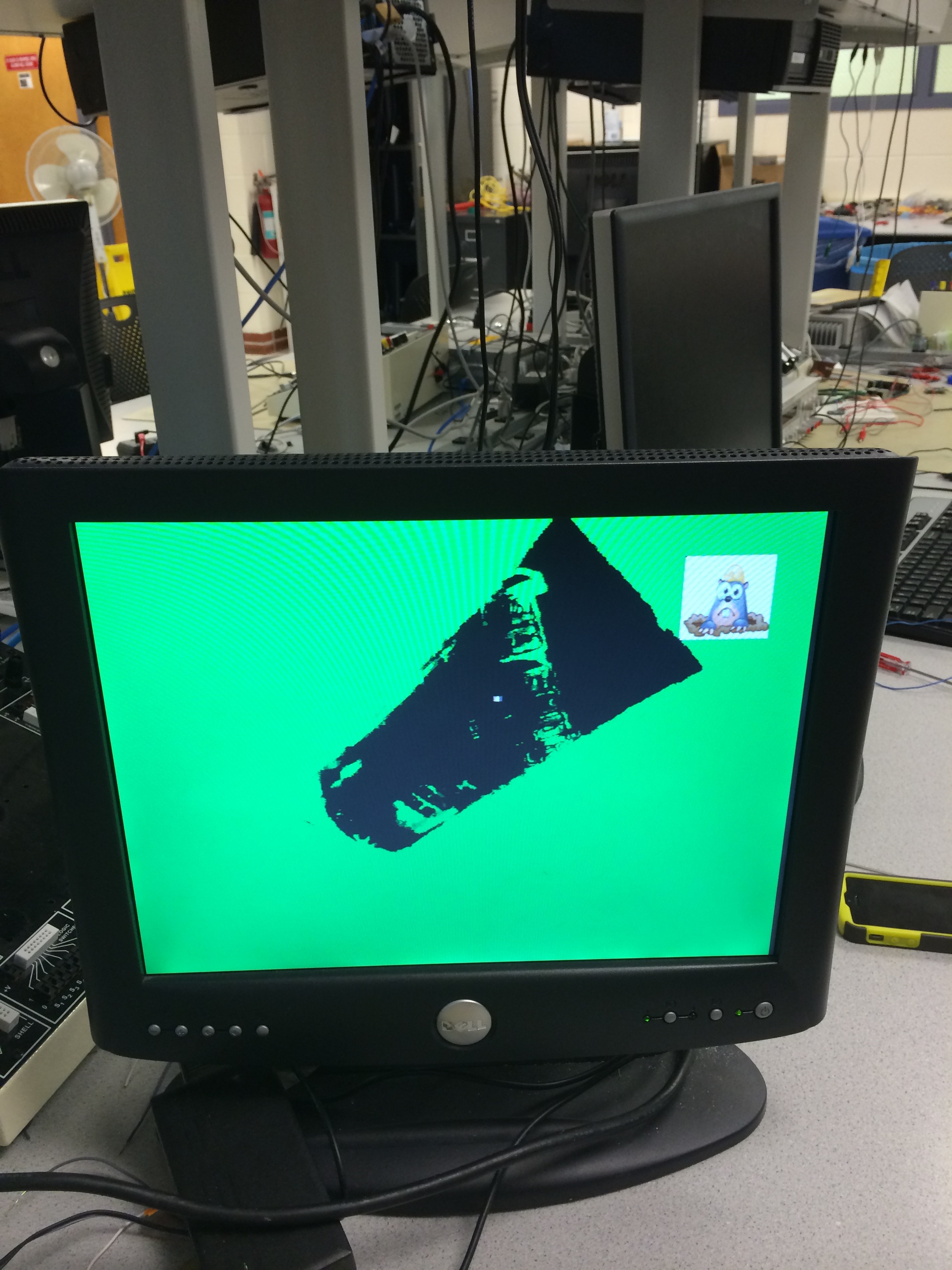
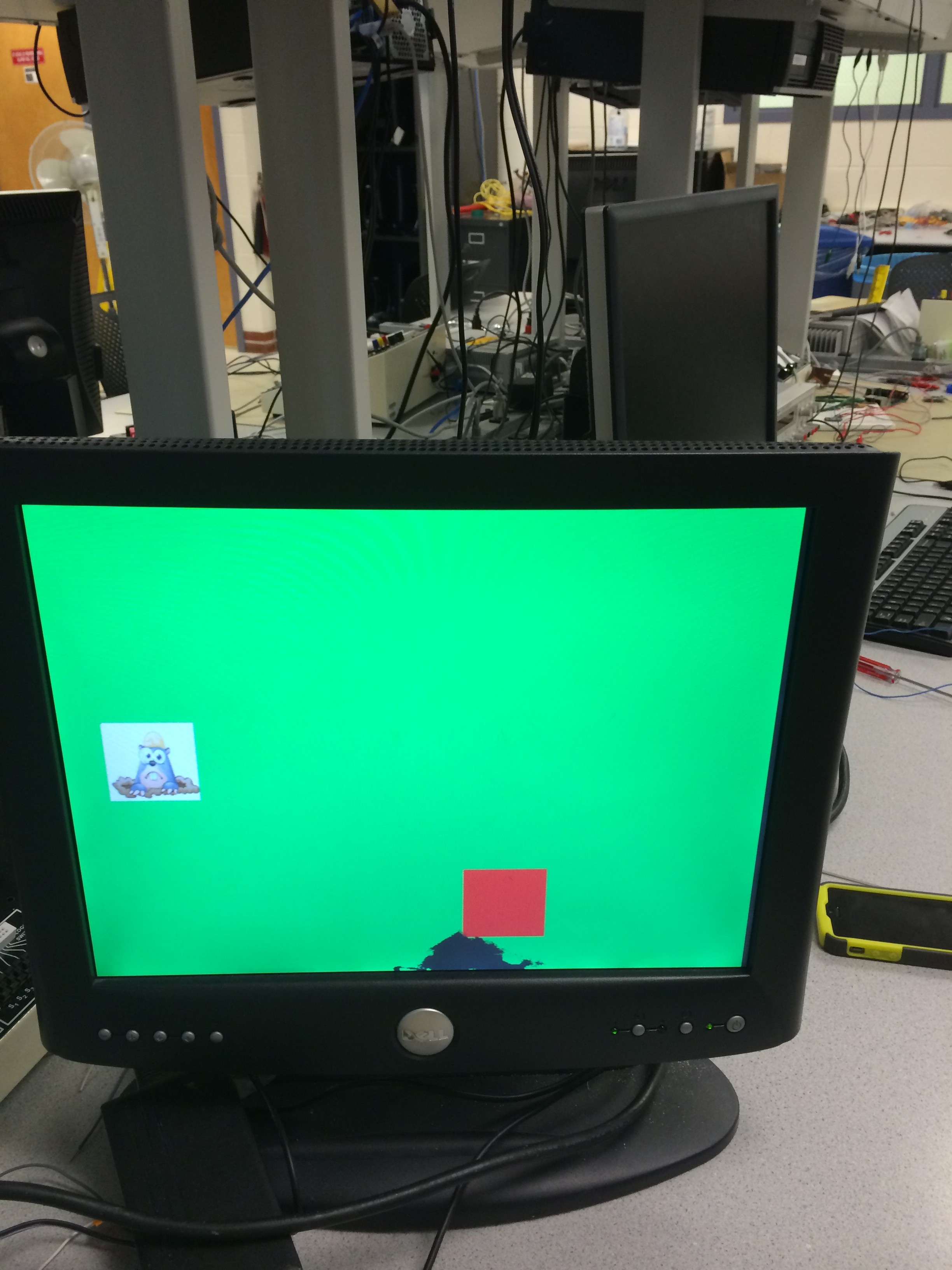
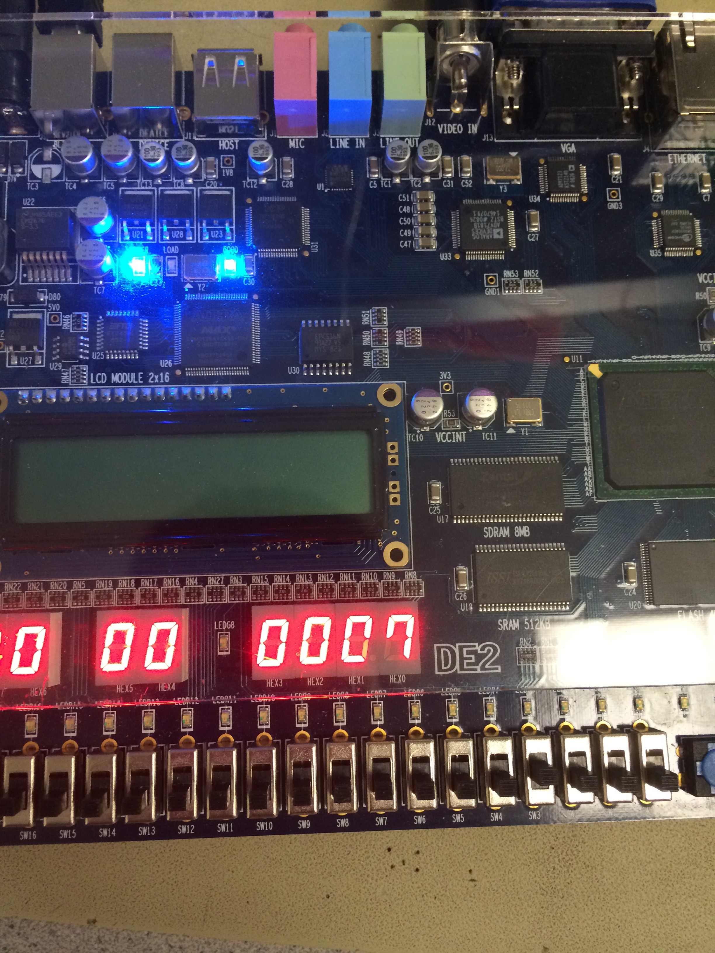
Here are some pictures of our Whac-A-Mole video game:
The three pictures below show that Moles and Bruce come out randomly from 12 possible position.
The first picture below shows that camera captured the hammer and marked a white dot at the center. The second one shows that the hammer hit the mole and we marked the mole with red square. The last picture shows the score we record on the segment LED.
Conclusion
In the project, we designed a gesture controlled video game "Whac-A-Mole" on altera DE2 board with an NTSC camera. Overall, the results of our project met our expectations at the beginning of the project. By implementing a green color detection algorithm, the game can recognize the green hammer to detect the hit. The player is supposed to hit the moles and avoid the image of Bruce. The goal of this game is to get highest score and enter the higher level.
Intellectual Property Consideration
Ethical Considerations
Legal Considerations
Code
TOP MODULE: DE2_TV
MATLAB for generate mif file and resize: GENERATE, RESIZE
Entire project zip: Whac-A-Mole
References
ECE 5760 home page http://people.ece.cornell.edu/land/courses/ece5760/
NTSC video http://people.ece.cornell.edu/land/courses/ece5760/video/index.htm
Acknowledgements
We want to thank Bruce Land for leading us to use the NTSC camera and the template, and for also teaching such a great course. We would also like to thank both of the TAs for their advices and endeavor to make the course better.