"The classic Tetris game controlled by the movements of your hand!"
This final project for ECE 5760 takes a very well known and classic game and puts a twist on it. Tetris was released in 1984 and since then has become an iconic game, garnering many reproductions and modifications to the original version. Our version of Tetris aims to produce the original Tetris game using a DE2-115 FPGA from Altera. Using VGA as an output and a camera that is able to detect skin tone, the user can play the game using motions that are sensed from their hand. There are four main regions of the screen. These regions control whether the block moves right, left, rotates, or moves down twice as fast. By filtering the video stream and looking for specific types of color in the YUV color space, the hardware recognizes when a user’s hand goes into one of the four sections and sends a signal to the game, instructing it what to do with the block. The game includes features that allow a player to move a piece left/right or rotate, count down time until the game ends, and also keep track of the score for the player. A player gets 10 points for each line that is completed. There are 7 different types of blocks that are chosen at random (with different colors) that drop down from the top of the screen. The games allows flexibility to switch between hand motion recognition or buttons on the FPGA to navigate the blocks and option for slow and fast speed of the blocks dropping down. The goal was to use our knowledge of hardware design to bring Tetris to the next level.
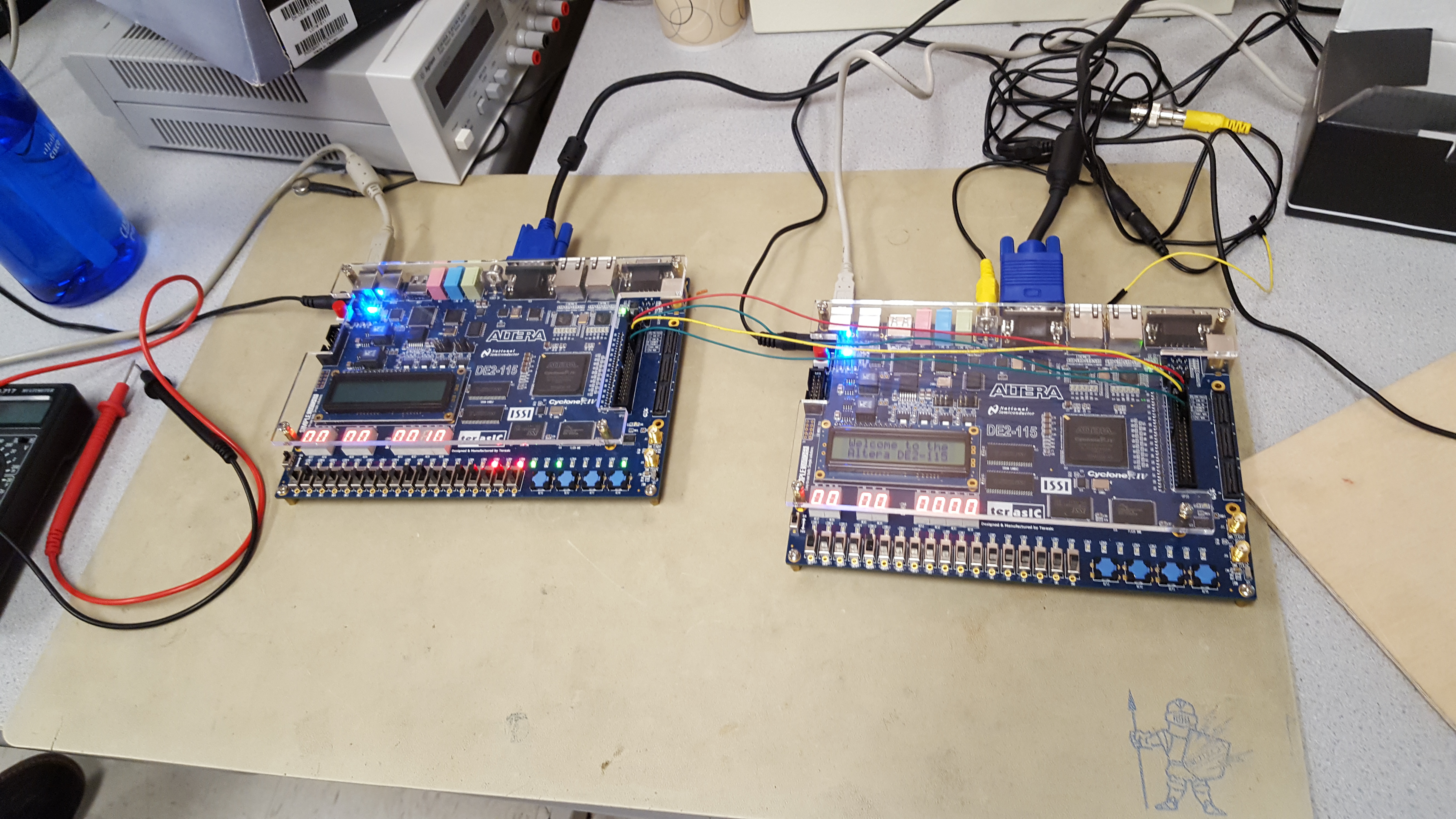
The finished product.
High Level Design top
Rationale and Inspiration
For the final project, the group wanted to work on something that had incorporated a few different aspects and topics from previous labs as well being able to actually make something fun. Naturally, hand motion Tetris was very suited for this, as it requires use of a TV decoder, knowledge of the YUV color space, dealing with outputting a signal to the VGA, designing hardware to implement the Tetris game, as well as dealing with DRAM and the processing of the signal from the camera. The project did not include any type of complex math other than some basic algebra to deal with moving the blocks on the screen and during the filtering of the incoming TV signal.
For sources of inspiration, we did look at other Tetris games to see what kinds of features that could be implemented. Some features that we saw included a preview of the next block to be dropped, a drop signal that immediately drops the block to the bottom of the screen, a hold feature that allows a user to save a block to be used later. While these features were nice to have, they weren’t necessary for the basic rules of the game. For example, we did not have a preview pane, which can be helpful, but we decided that it would keep the users more surprised. The original Tetris game made in USSR did have a preview pane, but it did not have the drop down or hold feature.
Logical Structure
Overall Design Approach
To create hand motion controlled Tetris, the project was broken down into two main parts: hand motion recognition and the actual Tetris game itself. These two functions were handled on two separate FPGAS as can be seen in the picture below:
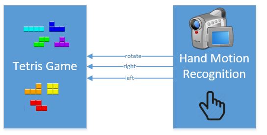
The left FPGA was taking care of the Tetris game dynamics and display while the right FPGA had a video camera and display hooked up to it to identify the hand motion. The two FPGAs communicate 3 pieces of information to each other: the signal to move the block left, right and rotate. The schematic to the right is a high level description of the two main components of the project and how they interact with each other, very similar to the physical picture of the two FPGAs.
The features that were added to this game included the use of switches to allow the user to control the blocks using buttons on the FPGAs for moving left/right/rotating or to control the movement with their hands. One of the switches also controlled the game speed. In addition to the different options for controlling the blocks, the FPGA also had a timer that counts down for the duration of the game round and keeps track of score on the hex display. Further details about the Tetris game and hand motion recognition portion are discussed in the hardware design section.
For the hand motion recognition portion of the project, it could be mainly broken down into two tasks: video signal decoding and hand recognition. As for the Tetris game portion of the project, it is broken down into many submodules. The high level description of each portion is describe below.
Video Signal Decoding
A key part of this project is being able to take a video signal from a camera and decode it. The mini cameras used in lab proved an NTSC signal which is fed into a video input port on the DE2-115. The board has a hardware decoder for NTSC built in. Once processed, the board then outputs an ITU_R 656 serial signal. The signal is then downsampled so that it can be displayed on the 640x480 monitor used in class and is also converted to YUV color space. The output is saved in SDRAM. The VGA controller module will then read it and convert it to an RGB scale.
Hand Recognition
Before converting to RGB, the YUV information from the decoded TV signal is primarily used to determine the location of skin in the picture. The specific type of YUV used in this lab is YCbCr. An interesting fact about human skin is that if you disregard the Y factor (which is the intensity), everyone’s skin tone falls in the range: Cb = [80:120] and Cr = [133:173]. With this fact, it becomes much easier to find the hand. Now, you can take any value that’s in that range and convert it to white while keeping all other values at black. From there, we figure out how many white pixels are in a given region and then output the correct signal accordingly.
In the Tetris Game portion of the project, it can be broken down into the game manager and further submodules that allowed the blocks to be moved on VGA, lines erased on VGA, and score/time keeping.
Tetris Game
The tetris game implementation consists of several different modules. First, we have an overall FSM that handles the general flow of the game. This includes invoking modules to draw and erase, knowing when to move pieces or draw new shapes, and determining when the game terminates. Most of the implementation details goes into a module called newShapeDrawer, which is essentially the main module that interacts with memory to actually draw or erase shapes, detect boundaries and obstructions, and detect completed lines. The outer FSM invokes this module with different modes - draw, erase, verify full lines, and erase lines. Within the newShapeDrawer, we have a look up table (LUT) called shapeBitLUT which provides encoded information about what shapes look like in different orientations, their colors, and where the bottom, left, and right boundaries are relative to the top-left x and y coordinates of the shape. In addition, we simplified drawing individual blocks with a module that draws 10x10 squares of a specified color. The module is used within the newShapeDrawer for drawing or erasing blocks, while reading the current board state is done separately.
Hardware/Software Tradeoffs
This game was entirely designed in hardware. As this is an FPGA course, the main goal is to design projects based in Verilog around hardware. It is possible to do a lot of the tasks in software, but that would greatly simplify most of the work and wouldn't achieve the result and experience we were trying to gain.
Standards
The only standards taken into consideration when working on this project was on the end relating to hand recognition. The two standards used were ITU-R BT.656 and NTSC. The latter is the original analog television system that was used in most of the Americas and was the standard for television broadcast until the mid 2000s when digital and HD TV began to take over. It is characterized by a frame rate of 29.97 frames of video per second. ITU-R BT.656 is the digital video protocol for physically streaming an uncompressed NTSC TV signal. It has a sampling frequency of 13.5 MHz for pixels and, in our case, was transmitted using 8 bit values for the Y,U, and V parameters in the YUV color space. Specially, the YCbCr color space was used, which is a subset of the YUV color space.
Existing Products
At this point in time, the idea of a wireless Tetris game. According to the Guinness Book of World Records, the first wireless Tetris game came about in 2006. Since there, there are many different versions of the game created that are wireless, including the use of Bluetooth to do the wireless communication.
Additionally, a previous ECE 5760 project, Anti Tetris Game (Spring 2013), uses a similar technique to play a Tetris game where you use your hand to tap the blocks to prevent them from getting to the bottom of the screen.
With these being mentioned, our project is different. If regards to more "professionally made" versions of the game, the use of a camera to find the skin on your hand is a reletively novel concept. Most games and systems that detect the hand (or something similar) use some sort of communication protocol or sensor. We are using straight video with signal processing. Additionally, our version created is very similar to the original version, but with that added twist; and is done completely in hardware. Most other versions of the Tetris game are created in some higher level language and is not done on as low as a level as this 5760 project.
Hardware Design top
As mentioned earlier in the High Level Design section, there were a few main components that needed to be put together to get the final project functioning correctly. This section will explore each of those components in greater depth.
Tetris Game
The Tetris Game FPGA can be broken down into 4 main sections: the physical hardware connections, overall game finite state machine, shape drawer, and the memory/VGA color mapping.

Schematic of Tetris modules.
Physical Hardware Connections:
As mentioned earlier, the Tetris Game FPGA does receive information from the hand motion recognition FPGA, and the two FPGAs must be wired together on the GPIO header to communicate the left, right, or rotate command from the hand motion recognition FPGA to the Tetris Game FPGA. In essence, the hand motion FPGA outputs voltages on GPIO ports 1,3,5 as to whether there was a left, right, or up hand motion gesture recognized from the video stream. GPIO[1] corresponds to the right signal, GPIO[3] is the left signal, and GPIO[5] is the rotate signal. The Tetris Game FPGA is using its GPIO ports as an input, so the FPGA must set its GPIO ports 1,3,5 to high impedance, otherwise, it could possibly damage the FPGA.
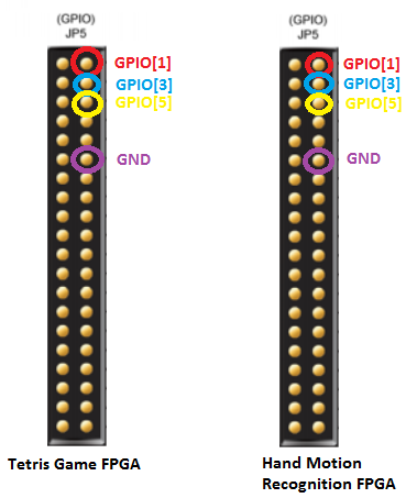
Schematic of How Both FPGA GPIOs are Connected.
Overall Game FSM
The overall game FSM takes care of running the entire game whose tasks are broken down into the flow diagram below:
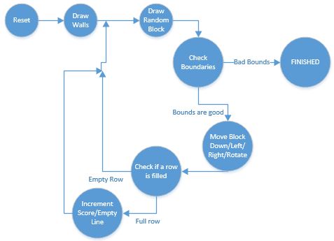
Finite State Machine Diagram of Overall Game
Every time the game is reset, the walls of the game are first drawn, and then a random tetrimino will be drawn onto the playing area. The FSM will check to see if the tetrimino moves down/left/right, that the tetrimino will be stopped by another tetrimino or wall. If there are no obstacles, the tetrimino will move in the direction specified. If the tetrimino is at the top and cannot move down, the game is finished, and LED0 lights up. Then the FSM checks to see if there are any rows filled in the location where the most recent tetrimino was dropped off. If so, that row will be erased, shift everything above down by 1 row, and increment the score. If there are no rows filled, the FSM will produce the next random shape and continue looping through until the game is finished. A general diagram showing which FSM states belong with which task is shown below:
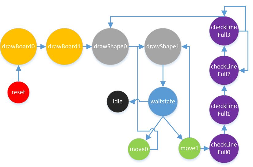
Finite State Machine Diagram of Overall Game
These different tasks will be discussed in detail later.
Overall Game FSM -> Drawing Wall:
Whenever the game starts up, the first thing that the FSM will do is draw out the two vertical lines that indicate the walls of the game. To do this, there were two states in the FSM dedicated for this task: drawBoard0 and drawBoard1. These two states output the correct signals to the VGA such as controlling the mux (so the VGA buffer would get the signals from this FSM instead of the other submodule called newShapeDrawer). First, the FSM would draw the left wall, which is at x=149 and 480 pixels long. Once the first left wall was drawn, the x coordinate was changed to x=491, and then 480 pixels would be drawn down the screen. Once the right wall is drawn, the FSM will go on to start generating the next random shape.
Overall Game FSM -> Random Shape Generation:
Two more states of the FSM fall under this task: drawShape0 and drawShape1. Determining the next shape and orientation are calculated in drawShape0. For random shape generation, the method for determining a shape and its orientation is in 3 and 2 bits, respectively. Then, two 15 bit registers are built, one with a random seed and another (called shape_orient_rand) with certain bits from the random seed in different order. There is a shape and orientation register that feeds into the newShapeDrawer module, and these two registers get bits 7 through 5 and bits 12 to 11 from the 15 bit shape_orient_rand register. Every time when in this state, bits 13 and 6 of shape_orient_rand are XORed together and shifted in from the left into the random seed. The shape_orient_rand register is also shifted to the left by one with the product of the XORed bits 13 and 6 shifted in. DrawShape0 also sets the coordinates of where that block should start (top of the screen) and ensures that the muxes will be muxing signals from the newShapeDrawer module to the VGA buffer, and not the signals from this FSM to the VGA buffer. The parameters for newShapeDrawer are set so that the newShapeDrawer will be in its draw mode.
DrawShape1 state will enable the newShapeDrawer module to start drawing the tetrimino. Since it takes more than one cycle to draw a tetrimino, the FSM will stall in this state until the newShapeDrawer indicates that it is done drawing the tetrimino on the VGA. The drawShape1 state will go to the waitstate. Because the FSM is running at about 75.6 MHz, it would not make sense to immediately erase the shape and redraw it 1 block down. The human eye would not be able to see the tetrimino if there was no delay in between. There were two registers (timeDraw and timeErase) used to control how long the the tetrimino should stay displayed and how long it should stay erased. The value of the registers were determined by switch 16, with the slow mode set to 60000000 and 1000000 for timeDraw(.794 sec) and timeErase (.013 sec), respectively. The fast mode is set to 50000000 and 3000000 for timeDraw(.661 sec) and timeErase (.0397 sec.), respectively. In the wait state, it will stall in the wait state until .794 seconds have passed with the tetrimino block still being displayed on the VGA. Then it will go to the move0 state.
Overall Game FSM -> Checking Boundaries and Moving Shapes:
The move0 state sets up the parameters so that the newShapeDrawer will erase the tetrimino at the same location where it was displayed. There is a flag called erasedshape that is set to 1 to indicate that the shape will have been erased after being displayed once. It will go back to drawShape1 then to waitstate. The erased shape will display on the buffer for .013 sec, and then go to the move1 state.
In the move1 state, it will check a newShapeDrawer signal called bottomwall, which indicates if there is a wall or block beneath the tetrimino before redrawing it 1 block down. If the bottomwall flag is not set, the location of the tetrimino is updated x and y coordinate-wise. The shape is then redrawn with the new coordinates, going through drawShape1 and waitstate. Then this cycle of drawing the tetrimino, waiting for .794 sec, erasing, waiting for .013 sec, and updating coordinates/checking boundaries is repeated until the tetrimino has reached the bottom or hit another block below it.
Overall Game FSM -> Checking for Full Line:
In order to detect when a full line is cleared, we need to have an efficient way to detect full lines. In the most basic solution, you would check every single line whenever you perform any operation such as a draw. However, we can instead check a range of lines once a block is permanently placed down. Since a shape’s position is defined by a point at the top of the shape, and we know each shape is at most 4 blocks high, we can check the y position and the 3 lines below that once we detect that we have hit a bottom boundary. Functionality of boundary checking has already been described, so we will focus on the few states to check full lines. When the outer FSM detects a shape has reached its final destination, it changes the mode for newShapeDrawer to verify full lines to mode 3. Given the y position of the placed block, it simply goes through the 4 lines, reading blocks until it either finds an empty block or the rightmost boundary of the game board.
Overall Game FSM -> Erasing Line:
With the functionality of checking for a full line, we can continue the functionality in the main FSM. So after checking for a full line, the outer FSM reads the result, and for each bit that is set, it invokes the line erase mode, mode 2. So say the result from the verify full line was 0011, it will invoke the erase line function in newShapeDrawer, which will be explained in a later section, on y_position+2, and then on y_position+3. Doing this means that this game is able to both detect and erase multiple lines even when a single block completed both lines. Like with many invocations of newShapeDrawer, the states involve checking the results and setting the appropriate registers to call the erase line functionality, and a wait state for newShapeDrawer to finish.
Shape Drawer:
The newShapeDrawer module is an essential component for the Tetris game to work. It consists of an FSM with many registers, wires, buses, submodule shapeBitLUT, submodule drawSquare_w, and multiple multiplexers. The FSM interacts will all of the other hardware within this module to generate the correct signals to the VGA for drawing/erasing the tetrimino or checking/erasing entire lines in the grid. This module has four modes: drawing tetrimino, erasing tetrimino, erasing line of blocks, and verifying if the next four lines are filled up with blocks. The FSM has states that are dedicated for each of the four modes. The diagram below shows which states are split up for the different modes. Note that there are only 3 different modes shown, because the erase and draw shape mode both utilize the blue branch, only the color being drawn is black instead of from the look up table for erasing as opposed to drawing.
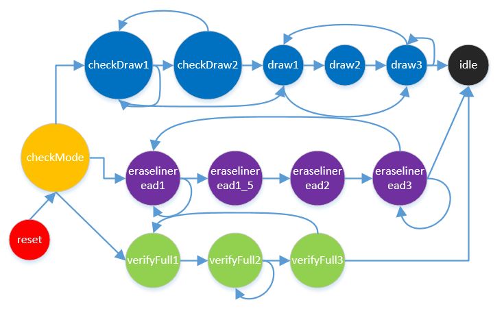
FSM of ShapeDrawer Module
Shape Drawer FSM -> Mode: Erase/Draw Shape
In this mode, it uses 5 states total to check the boundaries of what is about to be drawn and then to actually draw the tetrimino onto the VGA. For the first 2 states, checkDraw1 will start checking if the tetrimino at its current location will hit the wall or bottom before drawing it out. The LUT table has outputs that contain the x and y coordinates that should be checked to see if the tetrimino will run into a wall or another block. If the tetrimino will hit the wall or ground, it sets either the bottomwall, leftwall, or rightwall flag to indicate that the tetrimino will hit something. Walls take priority, so the FSM will not cycle through the rest of the boundary condition and will draw the tetrimino at its new location (since it knows the wall will be next to it and only sets the flag to indicate if we moved it one block more, it should not go in that direction). If there are no walls, the FSM will cycle through the rest of the boundary conditions to read from the VGA screen and see if there is another tetrimino that the current tetrimino might hit. Another important thing to notices is that it takes 3 cycles to get a reading from the VGA buffer, so checkDraw2 has a counter that stalls it for that long in order to get a valid reading from the VGA buffer.
If the tetrimino does not have any boundaries being hit, draw1-3 states handles the signals for drawing the tetrimino at its new location. Due to the way the tetriminos are encoded in the LUT, the drawSquare_w module is used to draw out the 4 blocks of a tetrimino. The LUT provides the relative coordinates of what blocks should be drawn from a top left corner reference. In the diagram below, it shows how the square tetrimino is encoded. The reference point is where the black dot is and the green squares are the boundary condition coordinates that need to be checked each time you want to draw/erase the tetrimino. The square numbers are how it is encoded in the look up table, and the draw1-3 states will cycle through this entire 4x4 grid. The blue square means that the LUT will have those bit numbers encoded with a value of 1 while the others in the 4x4 grid are 0. Whenever one of the squares has a value of 1, that square will be drawn by the drawSquare_w module with either the color that is encoded from the LUT or with black. If erasing, the color is black and if drawing, the color will be the LUT’s color. The draw1-3 state will set the appropriate coordinates for a square to be drawn in the tetrimino and color. Then the drawSquare_w module is enabled, and the FSM will stall in draw3 state until the drawSquare_w module has finished drawing 1 square. Then it repeats this process until all 16 squares in the 4x4 block have been checked and drawn.

How Tetrimino is Encoded in Look Up Table
Shape Drawer FSM -> Mode: Erase Line
There are several different states associated with erasing a line since it needs to deal with moving all blocks down, and erasing the very top line. Overall, moving blocks down involves reading the line above and writing it in the current line, working from the bottom up to the top. It starts in the eraseline1 state, which checks to see which line it is currently in. For most lines, it moves to the eraselineread1 state, and for the very top line, it moves to the eraseline2 state. The eraselineread1 state sets memory control to newShapeDrawer and waits to read the value of the block that is at the same x-coordinate, but one less than the y-coordinate. This means we read the block above the current block. We move to eraselineread1_5 once we finish reading and set the memory control back to the square drawer, and have it draw the block we just read at the current block position. At this point, it is at eraseline2, which is the same as when we are in the top line case as well. This state enables the square drawer and moves to our eraseline3 state, which checks our termination conditions. So eraseline3 will wait for the drawing to finish, then move to the next block in a the current line, else it will move to the line above. If we are at the top line and all blocks in the line were read, it goes to the done state, else it goes back to eraseline1 where the process is repeated.
Shape Drawer FSM -> Mode: Verify Line
Given a starting y position, this mode will check the line and the next 3 after that to see if the line is completely full of blocks. It starts off at the top line, checking every block in the line iteratively. It starts in verifyFull1, which sets registers to prepare for a memory read. For the current coordinates, it reads the contents. The verifyFull2 simply waits for a memory read to complete and then moves directly to verifyFull3. Finally, verifyFull3 handles the determination of whether to continue or not. If it finds an empty block, the line is not full and it immediately moves to the next line. Else, it will continue checking the line. If it checks all x positions and finds no empty blocks, it sets a bit in a 4-bit wide result that indicates which line is full. So if the second line from the top y position was filled, the result would look like 0100. After setting the new coorrdinates, it moves back to the verifyFull1 state. Once it checks all 4 lines, it moves to the idle state and sets the done flag.
Shape Drawer -> Translate grid to VGA Coordinate
When implementing shape drawer, we mainly worked with what we call “grid coordinates”. Grid coordinates specify blocks within the board. Our board space is 340x480 pixels, and each block is 10x10 pixels, thus, we have a 34x48 grid space. Making this abstraction allows us think more clearly about higher level functionalities such as reading certain blocks, rather than pixels. However, we cannot simply use grid coordinates when we want to access memory, so we use a translation to VGA coordinates. The Y coordinate is easily translated since we can just multiple the grid coordinate by 10. However, to translate the X coordinate, we need to multiply by 10, and also add 150 since the left border of the game starts the game board at the 150th pixel on the VGA. This implementation was simple to implement but provided many benefits through abstraction. Originally, we had thought to create two memory buffers, one that was actually a grid coordinate system that was 34x48, where we can get the overall state of the game, and then we could have a module to write the contents and translate it into the VGA buffer. However, we realized this did not provide any extra benefits over the final solution, and rather might have introduced delays, unnecessary work, and more memory usage.
Shape Drawer -> Draw Square Module
This module was created to handle the basic details of drawing 1 square of a 4 square tetrimino. It takes in inputs of its reference point (top left corner), the width/height, and what color the square should be. The outputs of the module are the data, address, and write enable for the VGA buffer and also a done signal to indicate that the module has finished drawing the square. There is a FSM within this module to handle drawing all of the pixels for the square. There are four states in which the module will output the the correct address, data, and write enable signal for the VGA buffer. The first two states actually are the signals for writing to the VGA buffer and the third state will increment the x coordinate until the row is finished. Then the y coordinate will be incremented by 1. This cycle of drawing row by row is repeated until it reaches the bottom right corner of the square. Then it transitions to the idle state, which outputs the done signal indicating that it has finished drawing the square. The diagram below shows the finite state machine diagram.

Finite State Machine of Draw Square Module
Shape Drawer -> LUT
As previously mentioned, the LUT provides encoded information about how the shapes look at different orientations, the color, and boundary conditions. The look up table takes in a shape, encoded as a 3-bit input, an orientation, encoded as a 2-bit input, and the x and y grid coordinates. It outputs a 16-bit shape, a 10-bit color, and 6 boundary conditions for each shape. The 16-bit shape encoding essentially defines the shape relative to the top-left corner of a 4x4 box. So the highest 4 bits encode the top row of the 4x4, and the lowest 4 bits encode the bottom row. When a bit is 1, that means there is a block, when it is 0, it is empty. So take for example a simple square shape, encoded as 0xCC00. On the top row we have two blocks then 2 empty spaces, as well as the second row. For the third and fourth rows, it is empty. Each of the 6 boundary conditions per shape,orientation pair specifies a coordinate and a boundary type. These coordinates are read in the shape drawer to see if there is a block there. We want to differentiate between a bottom boundary, which means the shape should no longer move and has settled, with a left or right boundary, which just means the shape cannot move in a certain direction. So for each boundary, we have 2 bits that specifies the boundary type. A left boundary is 0, a bottom boundary is 1, and a right is 2. When determining these boundaries, points that could be both bottom or a side, are set as bottom since it is priority over side movement. All boundaries were manually set and figured out.
Shape Drawer -> Memory/VGA Color Mapping
As mentioned, the LUT stores colors for each of the shapes. However, we encode 3 10-bit color values with just 10-bits by only specifying some of the bits of each color. Many of the least significant bits on each color do not produce visually different results, so instead, we use either 3 (red, green), or 4 (blue) bits for each color and then set the higher bits in the VGA color according to those bits, with the rest of the color bits as zero. So we use the 3 most significant bits for red, the next 3 for green, and the last 4 for blue. When we go to draw shapes, we are just writing these 10-bit color encodings into our memory buffer. We used a dual-clocked, dual-read/write port RAM with 10-bits for each of the pixels we display. This ends up using about 78% of the FPGAs total memory. One port of the memory is used by the VGA controller, which is in charge of the VGA signals. This port is clocked with the VGA control clock and is only read from. The other port is used by the overall FSM, the shape drawer, and the square drawer for both reading and writing. This port has two levels of muxing for control over the port, and is clocked with the SM control clock, a 75.6 MHz clock. Muxing between the overall FSM and the shape drawer is done by disabling the shape drawer and selecting the correct mux bits to allow the overall FSM to use the memory port. However, most of the time the shape drawer has access to the port. Inside, there is another mux between the shape drawer and the square drawer. Similar to the first scenario, when the shape drawer has memory control, the sqaure drawer is disabled and the mux bits are set. Otherwise, most of the time the square drawer will have control over the memory.
Timer and Scorekeeping
Two important aspects of the Tetris game is counting down until the game ends and keeping track of the score. The 27 MHz clock on the FPGA was used to keep track of the amount of time left in the game. A counter would until 27,000,000 and then subtract a 1 from the seconds timer. The seconds were kept track of using a “ones” and “tens” place. The minutes were kept track of using just one register. The timer starts at 2:00 minutes and counts down from there. The boundaries were taken into account (i.e. there being 60 seconds in a minute). When the ones place hit 0, a 1 was subtracted from the tens places. A similar method was used when the seconds counter reached :00. These numbers were all saved in decimal form. A hex display LUT was then used to convert the decimal numbers into the appropriate values for each hex displayed used.
Scorekeeping worked in a similar fashion. The score starts at 0 and the user gets 10 points for each line that is erased. An eraseline signal is taken in from the main game part. On the rising edge of the signal, 10 points are then added to the user’s score and displayed as the points accumulated. When the user reaches 100 points, the “tens” counter of the score is set to 0 and the “hundreds” counter is incremented by one. This is done in and combinational always block.
Hand Motion Recognition and Control
Video Signal Decoding
The video signal decoding was adapted from example code provided by Bruce Land on the 5760 webpage. Within this code, there are few modules that play an integral part in rendering the signal. It starts with a mini camera that gets plugged into the video input port on the DE2-115 board. Once turned on, this camera sends a video signal to the input port in NTSC format. More specifically, it uses ITU-R 656 protocol to do so. ITU-R 656 protocol is a digital video protocol used for streaming NTSC signals, similar to how wireless communications have protocols to send the information necessary. Once the signal is processed with the built in video decoder on the FPGA, the signal can than be worked with. In order to get the video to fit on the 640x480 screen, the signal is downsampled using a provided module. A separate module then takes the ITU-R 656 signal and converts it into YUV color space. This new signal is then taken and stored in SDRAM using a first in, first out (FIFO) method for the how to send the data out. The YUV data is used primarily for skin tone recognition in the next section. In order to get the the video to now be sent to the VGA screen, it is converted into RGB color space. With the signal now in RGB, a VGA control buffer reads in the value for each pixel of the 640x480 display and sends it out to the monitor. The program has the function to either display the original video or the raw, filtered video that just shows skin as white and everything else as black. This will be talked about in detail in the hand recognition section.
Hand Recognition
For this part of the project, it was necessary to discern what in the frame was actually skin and what was not. At this point, we have decoded NTSC video to work with. We adapted an M. Eng project from Thu-Thao Nguyen which also incorporated some example code from the 5760 website provided by Bruce Land. Both of these references and links to the work can be found in the appendix part of the webpage.
As mentioned before, one of the interesting facts about skin recognition is that independent of the intensity of the skin, the skin tones fall in the same general range on the UV components of the YUV color space. Therefore, we were able to disregard the Y factor of the YUV color space and just focus on the actual colors that were represented. Using the example NTSC code from Bruce, the decoded video signal was converted into the format YUV 422. However, this format shares the U and V information between two pixels, which means these values are only transmitted to the image buffer once every two pixels. In order to get a more exact value for the pixel colors, YUV 422 was converted into YUV 444. With this format, Y,U, and V each get 8 bits of information and is a more straightforward format. Additionally, we can now use these values to find R,G,B values on a range from 0 to 255. Another conversion was needed to change the YUV 444 color space into RGB values from [0:255] for R, B, and G. With these values, we can now relate RGB to YUV using some general equations. That was the next step. The two important ones to focus on for skin recognition are U = R - G and V = B - G. With these equations, we can calculate these differences for each pixel. We can break up the skin pixels into the following 2 categories:
10 < U < 74
-40 < V < 11
Additionally, it turns out that the blue part of RGB is the least important in regards to skin color. For this reason, just the U factor was taken into account. After doing some testing with the VGA output, it was determined that a good range to take into account for skin recognition was U > 60 and U < 256 (or R-G > 60 and R-G < 256). This produced minimal amount of errors, such as accidentally mistaking something else in the room for skin. If the U value was in this range, a 1 was stored in the VGA buffer. If the U value was out of this range, a 0 was put in the buffer. This way, there was now just a simple black and white image that showed where the hand was in the frame.

Hand in gesture control system
The next step was actually determining where the hand was and sending certain signals to the game. The four choices in signals were to move the piece to the right, left, down at 2x speed, or rotate clockwise. To accomplish this, the screen was broken up into four sections as follows:

VGA Regions of the Screen and Their Bounds
The boundaries for making the piece go left or right were at X-pixel 100 and X-pixel 550, respectively. The boundaries for making the piece rotate or go down were at Y-pixel 50 and Y-pixel 400, respectively. These values were tinkered with until that seemed reasonable given an actual user. Additionally, due to the fact that the skin detection algorithm also will detect the user’s face, it was important to make the regions relatively small compared to the space in the middle. One the user moves their hand into one of the regions, a counter counts how many white pixels are in the given region. The limit for the left and right regions were 425 white pixels. This is due to the fact that the user will have their palm facing the screen (meaning a good amount of white pixels) so the game needs to register that their palm is in the region as opposed to another item in the room. The limit for the rotate region was 325 pixels; slightly less than the left and right sections. This is due to the fact that the user’s hand is perpendicular to the region and therefore, inherently, won’t have as much as the palm in the region. Increasing the size of the region was not practical due to the fact that the head is always towards the top of the screen. The down region on requires 225 white pixels to send a “1” to the down movement of the game. This is because it is naturally difficult to keep the palm exactly parallel to the screen when move the arm down. People have a tendency to rotate their palm downward as they move their arm downward. This was accounted for in the smaller number of pixels need for this section. In the end, these hand movements simply send a high signal to the appropriate movement. This signal is taken as an input to the game module and handled from there.
Testing Methods top
Tetris Game Testing
The kinds of testing for all levels of design involved just using the monitor to see what was being displayed, utilizing the LEDs/switches/keys, and testing individual submodules before integrating them into higher level modules. For example, we tested the drawSquare_w module to ensure that it could draw a single square in different locations on the monitor, before then using it in the newShapeDrawer module. Then, we ensured that the newShapeDrawer could control the drawSquare_w module to draw several squares. Whenever something wasn’t working, we would use the LEDs to indicate if certain states were being entered or if certain values were being set.
The LEDs were very helpful for boundary condition checking, because it was hard to see if the wall flags were being set properly at the right time. In addition, VGA memory had to be read to see if there were other tetriminos in the way of the current tetrimino. The LEDs were very useful for indicating if something was being read from memory.
In addition, whenever we wanted to test a lot of different values and didn’t feel like recompiling the FPGA for different values, we would route it to switches, saving us time. For example, when we were testing erasing an entire line and wanted to pick which line to erase, having the coordinates hardcoded to the switches saved a lot of time in debugging.
Another way of testing the Tetris game was having the left/right/rotate signals based off of key pushes instead of video to ensure the game itself was working. It is better to ensure the game is working by itself before integrating it with the hand motion control portion of the project.
When figuring out the GPIO input and output pins, we made sure that the grounds were connected correctly by probing the FPGA with the continuity test of the multimeter. Once it was tested that both FPGAs were grounded together, we checked that the hand motion recognition FPGA was output the voltages correctly before connecting that wire to the other FPGA. With the Tetris FPGA, we made sure that the input pins were set to high impedance before the wires from the other FPGA were hooked up. Also, LEDs were hooked up to the three GPIO pins to ensure that the information was being sent correctly from 1 FPGA to the other.
Hand Recognition
As with testing the actual gameplay, it was very simple to test all parts of the video component of the game. First, seeing whether or not the actual video was being displayed on the screen was a simple as looking to see if anything was output on the VGA screen. We began with functional base code, which was a huge help, allowing us to focus on the actual intricacies of the project rather than whether or not the video was being display.
After filtering the signal and telling it to look for skin tones, SW[17] was assigned to change between original video mode and the filtered video mode. Using the VGA screen, the parameters were changed in regards to the range of U to detect the skin. As described above, the optimal level was found where there were minimum errors regarding other objects being mistaken as skin. Several different “subjects” with different skin colors were used to make sure that all different types of skin could be recognized.
The last step for testing the hand recognition was making sure the program was able to tell which sections of the screen the hand was in. Since only a “high” signal will be sent up having enough of the hand in the region, each signal was sent to a different LED on the board. This is also how the regions were tweaked and when it was discovered that certain regions needed different boundaries and amount of white pixels to register a “1”. Upon moving your hand into different regions, the appropriate LEDs would light up, indicating the correct movement.
Results top
YouTube video of the hand motion controlled tetris game:
Speed of Execution
The Tetris game was able to be reproduced and play in real time. The speed of movement of blocks is approximately one space (or 10 pixels) per second. Compared to the VGA clock, which is 25.1 MHz, this is extremely slow. This allows for plenty of computation time.
Another positive to the blocks moving so slowly is that any processing needing to be done on the camera side of the project can be done. Even though it needs a few thousand clocks cycles to count up all of the white pixels in the frame and then send a "high" signal after counting through all the pixels, this, again, leaves plenty of time for the game part of the program to recognize that an input has been received and then actually move the block accordingly. Even if you take into accound erasing the current shape and then redrawing it in the new location, there is nothing to worry about in regards to speed of execution.
Accuracy
In regards to the actual gameplay, the movement of the blocks is very accurate. This is due to the fact that the height of the VGA is divisible by 10, which is the height of each square that makes up every block. This makes it easy to make sure the block stop when it gets to the bottom of the screen. Additionally, we made the width of the game area also divisible by 10 for the same reason. Using the 2 vertical lines that define the game space, boundary conditions can be set to make sure the blocks don't go out of the gaming area.
Moving blocks left or right works well with the controls. However, the game currently has a know issue when moving pieces are moved and there is an object diagonally across from it. So it will essentially end up "eating" that block. Most of the solution is already implemented - the boundary system. By implementing more boundaries to check for these diagonal cases, which only requires the LUT to have these boundaries defined and some extra bus between the LUT and the shape drawer, the issue can be solved. However, it still works as it is fairly well.
When looking at the video signal that comes in to register the movements of the game, it does a very good job of recognizing when there is a full hand in the correct region. We also make sure that there isn't a continuous stream of "1's" being sent to the game, a movement of the block is only checked for every .5 seconds. Otherwise, the input from the video program is not considered. This allows us to get accurate movements of the pieces and not to accidentally register any extraneous signals.
Safety
There are no moving parts to this lab and no additional circuits or hardware to take care of. For this reason, the game is a very low risk game to play. The only safety issue to consider is making sure that no one else is in the user's range when moving their hands around. Ample space should be give to play this version of Tetris.
Interference
Our game will not cause any types of interference with any other groups' projects. There are no wireless signals being sent at any time and no CPU noise will interefere. The only type of interference our game would cause is if another group is doing a project that relies on skin detection. With this being said, the skin from any of our users might interfere with the functionality of another group's design.
Usability
The usability of this game is extremely high. It takes no prior technical or engineering experience to play the game. The dyanmics are identical to that of the original Tetris game. Many people are very familiar with the game already. If not, there is an abundance of online resources someone can use to get an idea of how to play the game correctly.
The video interface also allows the user to orient themselves correctly in front of the camera ahead of time. Users have the option of displaying the video feed on the VGA monitor before they begin playing. From there, they only need to flick a switch and can then get to the actual game display. The score and time are clearly displayed and easy to read on the hex display and requires no user interaction to change those. The only other user interaction is pressing the reset button to start the game.
Conclusions top
The Tetris game worked relatively well and ended up allowing the users to have almost all of the original functionality of Tetris. The blocks have the option of moving quickly or slowly, allowing the user to play on either a hard or easy setting. When a line is complete, it is accurately erased and updates the score.
However, some parts did not come out as expected. When making Tetris, there are a lot of boundaries conditions that make the game work correctly. When rotating a piece while it comes into contact with another piece, sometimes a part of one piece overlaps the other one. This is a small detail and doesn’t affect the overall playability of the game.
Originally, the entire program was going to be on a single FPGA. Difficulties with integration drove us to use 2 separate FPGAs. With this approach, the user can now see both the Tetris game they are playing and the output of the video camera to make sure their hands are in the correct locations and that the moves are actually being sensed.
In regards to the hand recognition, upon setting the regions correctly, it is relatively accurate when detecting the correct moves. One thing we could have done differently is adding additional filtering to the video to avoid categorizing some objects in the room as skin.
Other aspects that could be added to the game include having a box that shows the user what the next upcoming piece is and also have a “hold” box where the user can choose a piece they would like to hold for future use.
Conforming to Applicable Standards
As discussed earlier, the only standards used were those relating to the NTSC video and the ITU-R 656 protocol used to stream the video to the FPGA. The video is streamed at 29.97 frames per second and the code for this and the ITU-R 656 protocol was used from previous students which are referenced below.
Intellectual Property Considerations
The entirety of the physical game was build from the ground up. In regards to the hand recognition section, code was used from a previous M. Eng project. The basis for this code originated from Bruce Land’s NTSC example code on the 5760 website. None of Altera’s IP was directly used. The example code we used originated from an Altera example at some point. However, most of the IP from Altera for NTSC video was for the DE2, so it was more beneficial to start with base code for the DE2-115. There was no reverse-engineering done in order to complete our project and there does not seem to be any patent opportunities for this game. Tetris is a well established game already and there have been versions in the past that use a wireless concept to control the game.
Legal Considerations
There are no legal considerations for this lab. Any code used was in the public domain and was available for our use. The applicable standards were conformed to in their respective modules.
Appendix top
A. Distribution of Work
Christine- Square drawing module
- newShapeDrawer draw/erase shape mode aka boundary conditions
- shapeBit Look up table boundary conditions
- Tetris Game FSM - moving shapes down,left,right, rotate with boundary conditions
- Hardware GPIO Pin Integration between 2 FPGAs
- Website Design
- Square drawing module
- Video Interface with Controls
- Timer and Scorekeeping
- Website Design
- Hardware, Testing, High Level Content
- Memory, lcocking, and coloring
- Board state/block storage architecture
- shapeBit look up table encodings
- Shape draw/erase scheme
- Full line detection and clearing
- Game termination
- Testing and debugging
D. Code Listing
The full source code for our project is located at tetris_code.zip. Note that the code is broken up into two folders: The physical game dynamics and the hand detection code..
References top
This section provides links to external reference documents, code, and websites used throughout the project.
Richard, Christine, and Mayur