HPS Code
We use PIO ports to send data between the FPGA and the HPS. In particular, we send values like the initial rotor positions, rotor turnover positions, the reset signal, and the 13-letter chain found from our graph. While we split this into two 12 letter sequences excluding the last and first letter respectively, we also split those two 64-bit sequences into 2 variables of 32 bits each to pass through our PIO ports. The FPGA passes to the HPS the found plugboard mappings from the Bombe module and also ctrl signals that indicate whether the FPGA has found a valid mapping or is done with computation.
Hps_driver.c is the HPS code that runs in companion with the FPGA code. The main purpose of the HPS code is that it serves as the GUI that takes in user commands. After initialization, parallel port connections, and declaration variables, the while(1) loop takes in user input. It first calls the printf function to ask the user for the command and then uses the scanf function to take user input and store that in the input buffer.
In the if statements, we use the strcmp function to check the input_buffer for certain commands. After the user inputs in “reset”, they will first be asked to enter “Y” or “N” to decide whether the program runs with default settings. If the answer is yes, it will print out the default settings, which involve a default test case we have. Otherwise, it will prompt more scanf functions that ask the user to input rotor position, rotor turnover letters, input message, output message, and rotor positions. Once that information is received, the values will be assigned to the output ports to the FPGA. If the user types in the “read” command, all the settings and the discovered plugboard mappings will be displayed in a formatted and organized manner. Since the discovered plugboard mapping is most likely a partial mapping, we then use this as an input to our Bombe checker.
Bombe Checker in C
The Bombe machine is an effective tool in eliminating a large number of incorrect plugboard settings, but after such elimination, there is still a large amount of possible but unverified plugboard settings. We know that a letter may or may not be matched in a plugboard and once it is mapped to another letter, those two letters are matched to each other. One needs to take all the unmatched letters in the plugboard and test out all the possible unique and non overlapping pairs. Back in WWII, this process involved an abundance of manpower and effort. We condensed this time intensive process to less than a second by developing a recursive C program that can create unique and non-overlapping pairs of letters from a list of unique letters.
Before digging into the detailed implementation, let’s first look at the complexity of such an algorithm. The number of possible pairs can be summarized by this equation:
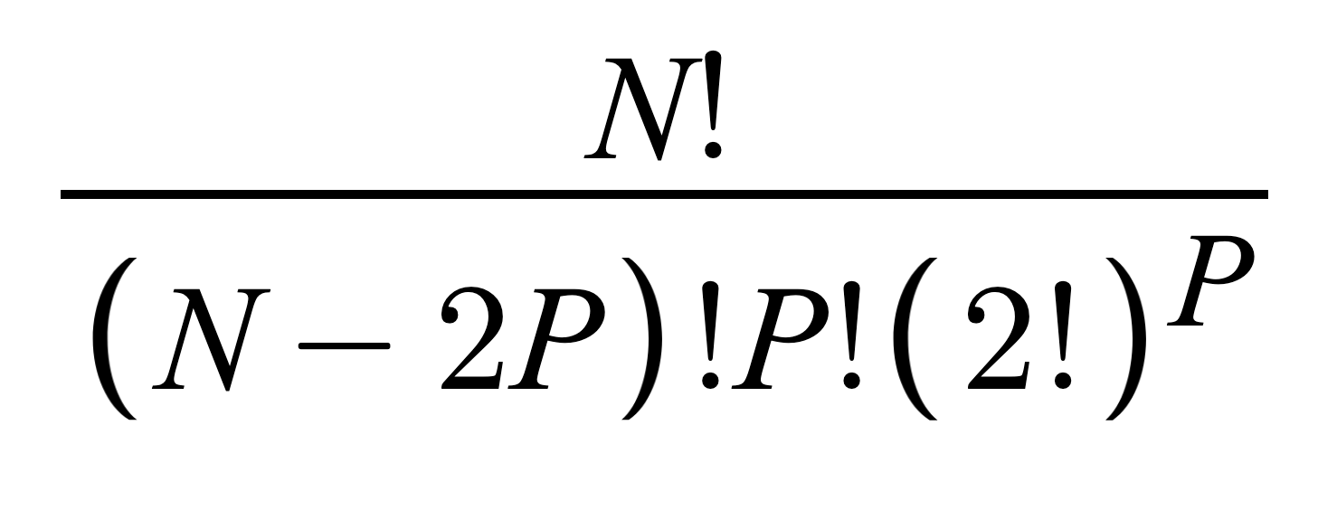 Equation 1: Number of Permutations
where N is the total number of letters to be paired and P is the number of pairs. To select P pairs from N objects, there are
N!/(N-2P)! ways. Since the ordering of those pairs and the order of the two objects in the pair do not matter,
P! and
(2!)^P are in the denominator. For example, there are
4!/((4-22)!2!(2!)^2)=3 unique pairs, as shown in the figure below. In our case, the maximal number of unique and non-overlapping pairs we will need to test is
14!/((14-62)!6!(2!)^6)=945945 number of pairs, when we are trying to find 6 unique pairs in 14 letters. While this looks like a huge number, it actually does not take the C program that long to run if we keep optimization in mind while implementing the algorithm. We later use the number of possible permutations to verify the correctness of our algorithm.
In the main function of the program, we first call the
pairing_cleanup(). This function takes the output plugboard setting from the Bombe machine and creates an array to store the undetermined ones. It accomplishes this by labeling whatever already appears in the Bombe output in a 26-index array. Each index represents a letter from A to Z. After the labeling, we simply read out all the indexes that are not labeled and put them in an array. At this point, we will have an array with zeros and the same length as the number of unmatched letters. Each index of the
unMatchedLetter[] array corresponds to an unmatched letter.
After we obtain the unmatched letters, we call the recursive function to find all remaining possible pairs. The
findPair() function takes three inputs: number of pairs, an initial i value, and an initial j value. The number of pairs is the same as the number of recursive levels and ‘i’ and ‘j’ indicate the indexes of the first number and the second number that we are currently searching for. We also implement helper functions including
findLastUnmatched() (that finds the last unmatched letter in the array),
findSecLastUnmatched(),
findFirstUnmatched(), and
printUnmatchedLetter().
As mentioned before, if we are looking for N pairs, then the recursive function will be called recursively for N times. The variable level is decremented at each recursive cycle. When the level variable is larger than one, the function will find the next possible unmatched pair by searching the index after the current i and j. Once a possible pair is found, the current i and j indexes of the
unmatchedLetter array need to be labeled to ensure the uniqueness of each pair. This is because on the physical plugboard, a letter can only be matched once. Then the
findPair function will be called recursively with
level-1. If i and j reach the end of the array, it means that the current level is already searched extensively; therefore the function returns. Whenever we find that the current index is not a correct plugboard setting, we need to unlabeled the index. There are also a series of boundary conditions to ensure nothing is out of bounds.
The base case is when the level is one, which means the function already finds the number of pairs we would like to try. We implemented an
enigma_test() function to be called here. It runs our Enigma machine in C through the
enigma_running() function and compares if the decrypted crib is the one we expected. If they are the same, the function will print out “Correct, continue?” and wait for the user input. When the user inputs “Y” the program will continue running to try to solve for other possible plugboard settings. If the
enigma_test() function does not return a positive result, the label on the i and j indexes will be removed and i/j will be incremented in a manner that will cover all the possible cases.
For example, the below figure shows how the function operates when it tries to find two pairs in four letters. First,
unmatchedletter array starts with 0000 since none of the indexes are labeled. In level2, the function first tries to grab the left two letters. “i” starts at index zero, and “j” starts at index one. Then the recursive call is spawned to level one, where it grabs the last two. If the plugboard setting is not matched, it returns to level 2 and then j will be incremented by 1. Therefore, 0 and 2 indexes are labeled. As you can see, this algorithm will then follow this routine and test three unique plugboard settings.
As mentioned before, if we are looking for N pairs, then the recursive function will be called recursively for N times. The variable level is decremented at each recursive cycle. When the level variable is larger than one, the function will find the next possible unmatched pair by searching the index after the current i and j. Once a possible pair is found, the current i and j indexes of the
unmatchedLetter array need to be labeled to ensure the uniqueness of each pair. This is because on the physical plugboard, a letter can only be matched once. Then the findPair function will be called recursively with
level-1. If i and j reach the end of the array, it means that the current level is already searched extensively; therefore the function returns. Whenever we find that the current index is not a correct plugboard setting, we need to unlabeled the index. There are also a series of boundary conditions to ensure nothing is out of bounds.
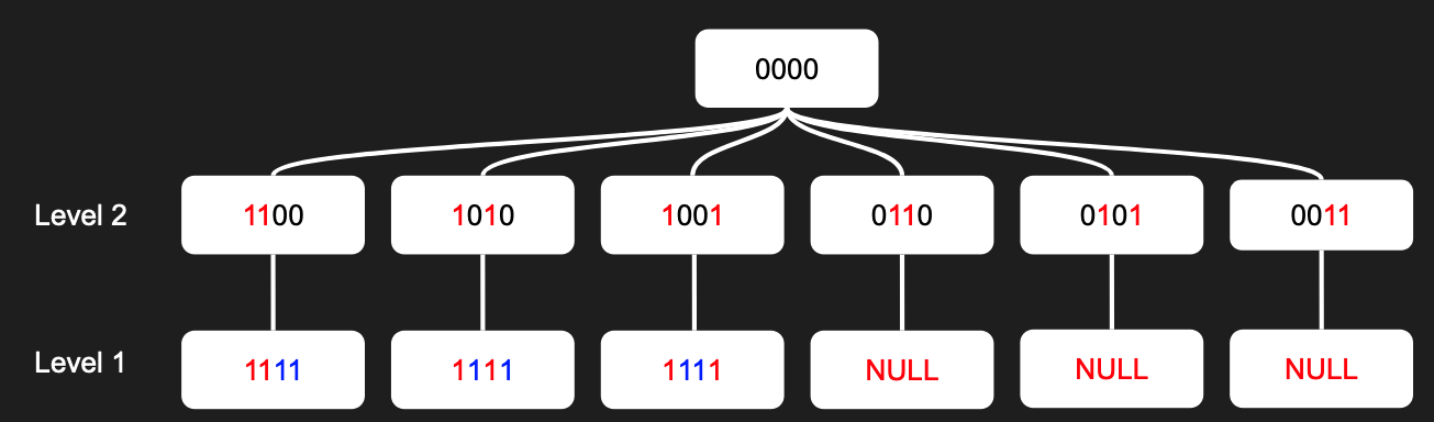 Figure 6: Recursion for Finding Remaining Plugboard Permutations
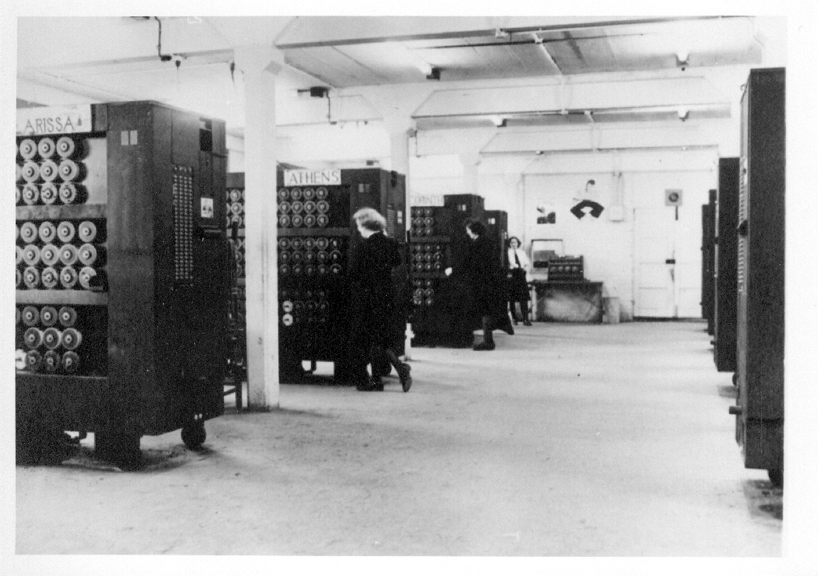
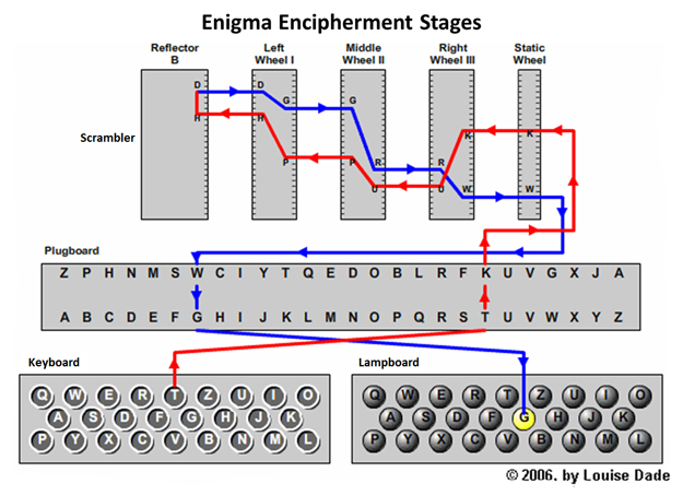 Figure 1: Enigma Design
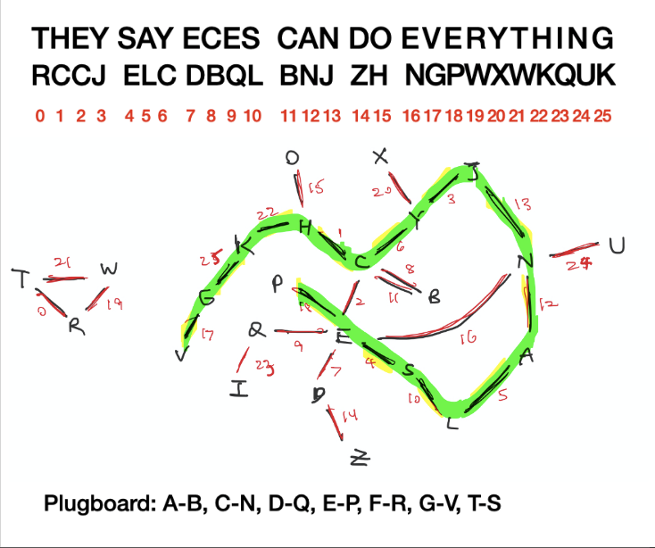 Figure 2: Example Crib and Menu
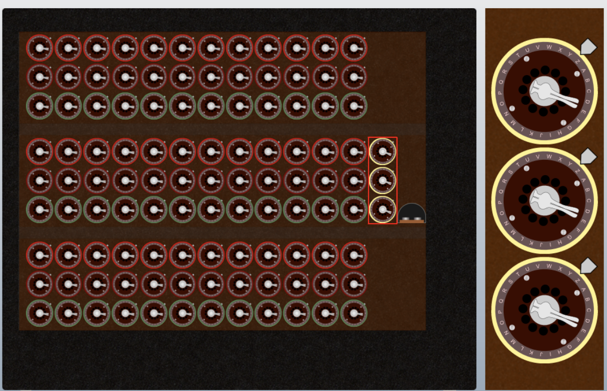 Figure 3: Bombe Machine Drum Arrangement
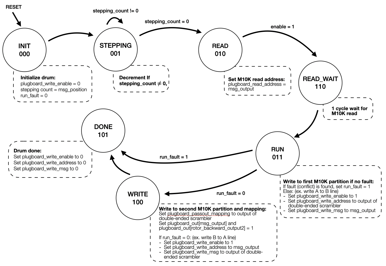 Figure 4: Drum Module FSM
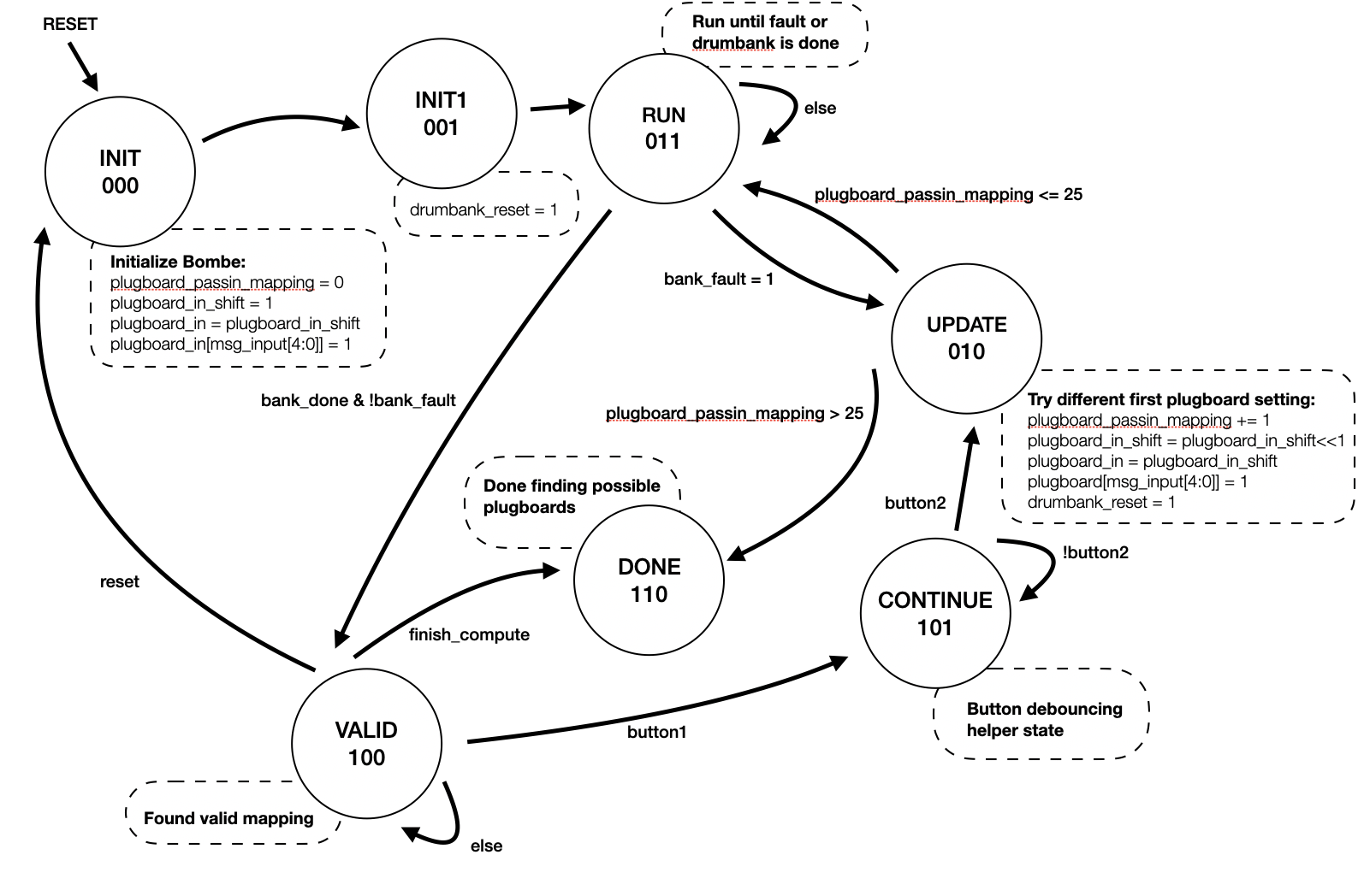 Figure 5: Bombe Top-level FSM
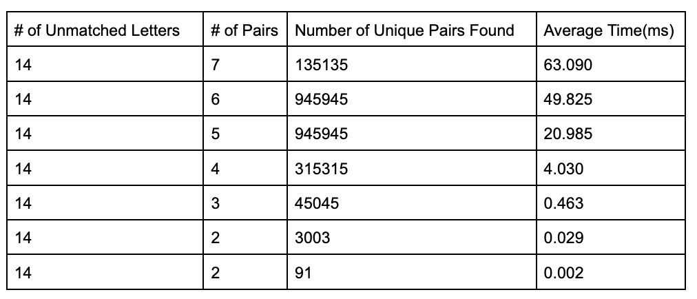
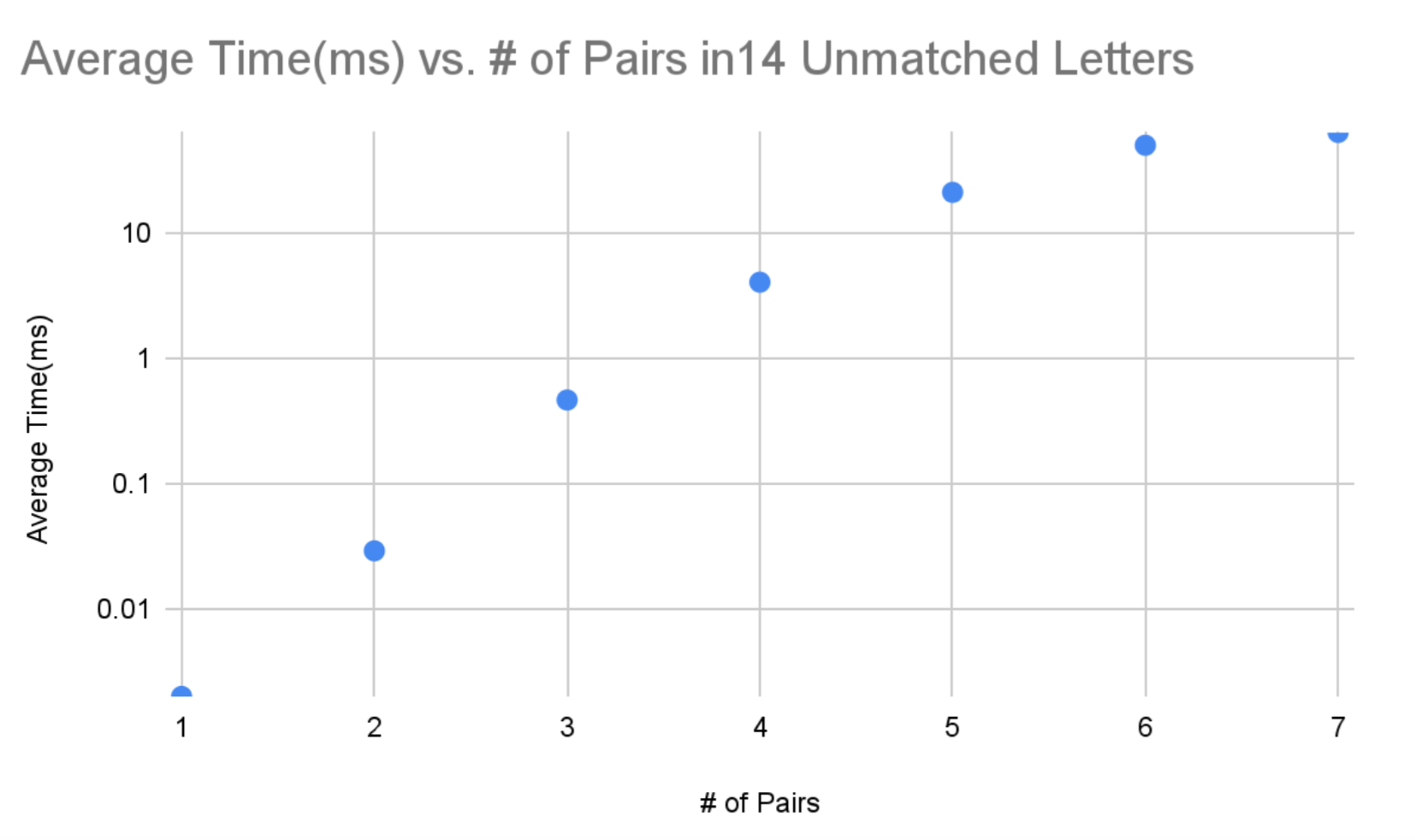 Figure 7: Average Time vs Number of Pairs for 14 Unmatched Letters
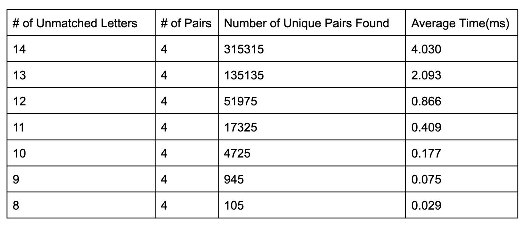
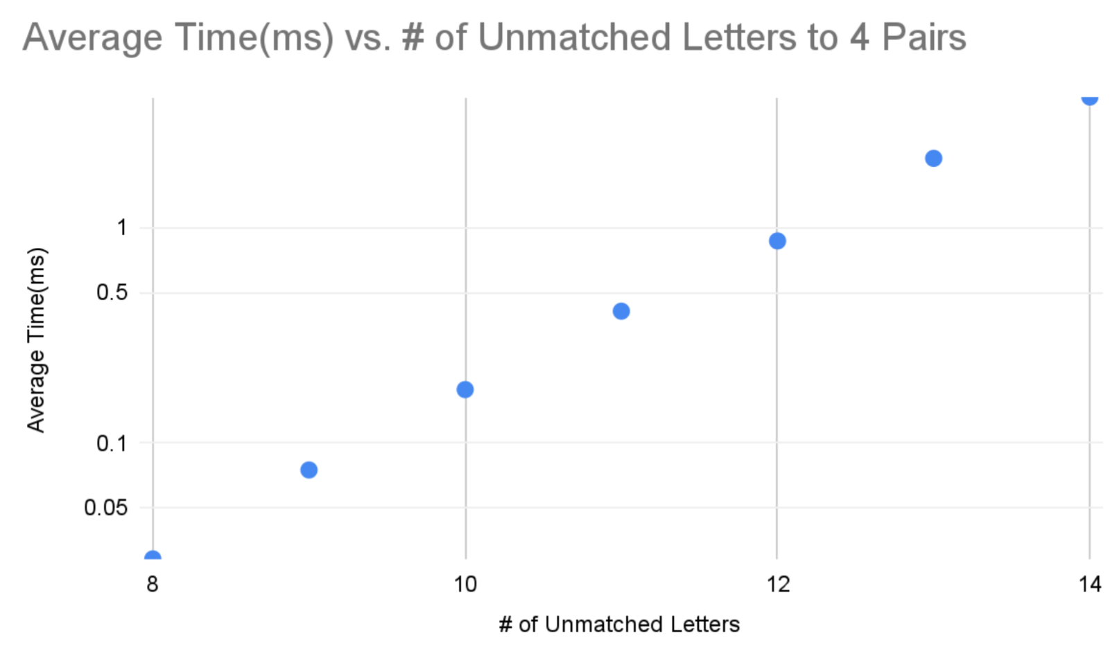 Figure 8: Average Time vs Number of Unmatched Letters for 4 Pairs