The first example uses a NiosII cpu with JTAG UART, interval timer, two input and two output ports, and an LCD port. The timer was set to default to 1 mSec in the SOPC. This setting seems to be picked up by the OS library builder in the IDE program. For real applications, it should probably be set to 10 mSec. Changing the timer in the SOPC to 10 mSec, rebuilding the hardware, then recompiling the GCC program automatically sets the MicroC/OS system tick to 10 mSec. The
sof and ptf files define the system. 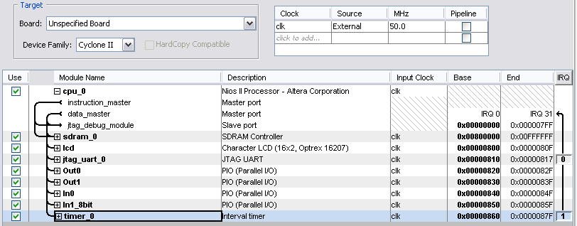
The top level module connects
Out0 to a DDS (direct digital synthesis) unit for sine wave production. In0 is connected to the DE2 switches and the 8-bit In1 connected to the pushbuttons. See NiosII C examples, example #3 for more information on the DDS. Note that in system.h (generated by the library builder) that the names of the i/o ports are UPPERCASED. After the workspace is defined in the IDE, the system library properties need to be set up for the RTOS as shown below. Clicking the RTOS Options button allows you to choose exactly what OS modules you want to include. The default is to include every module, which results in a minimum 120 kByte executable. The Altera Tutorial gives more detail on setting up the system library. 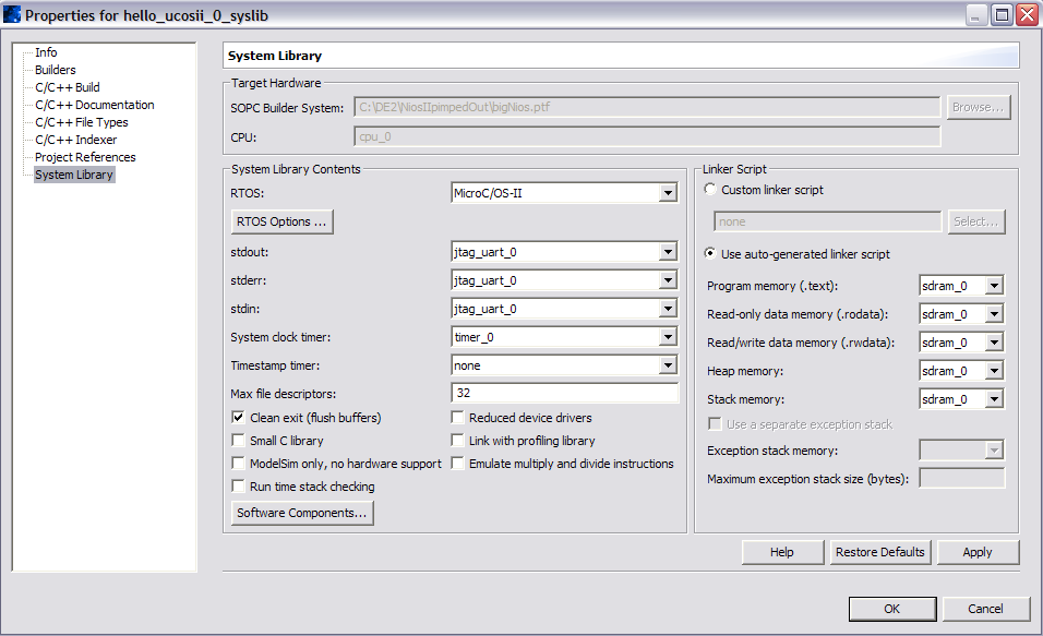
The GCC program structure is very simple:
- The
maindefines OS data structures and tasks. OS data structures (in this example, a message queue and a semaphore) used by more than one task need to be global. - Each task is written so that it never terminates. This implies that task local variables are effectively static. The task stack must be made big enough to hold all local variables (including those defined in functions within tasks) and the task context when another task is running.
- Task 1 controls a hardware DDS unit running in the top level Verilog module. The DE2 toggle switches control which octave is played.
- Task 1 sends a message to Task 2, which prints the message.
- Task 1 controls Task 3 via a semaphore so that Task 3 runs every time Task 1 does, unless Task 1 suspends Task 3 using a pushbutton.
- Task 2 waits for a message, prints it and waits again
- Task 3 waits for a semaphore, prints the system time, and waits again
OSTimeDlyHMSM causes Task 1 to block for a time interval, but does not affect the execution of other tasks. OSQPend causes Task 2 to wait for a message in the queue, while OSSemPend causes Task 2 to wait for a signal from Task 1. If a task does not call an OS service which causes it to wait, then no lower priority task will ever execute! A slight modification to the top-level Verilog module connects output port Out1 to the green LEDs. The GCC program was modified to include a fourth, low priority task, which does not block using OS calls, but runs at full speed. With task 1 pacing the first three tasks at one/sec, the LED blink rate suggests that task 4 is running about a million times/sec. When task 1 is running at about 140/sec (
OSTimeDly set to 7 mSec), task 4 never gets a chance to run because task processing, context switches and OS overhead is eating the cpu.
The example uses the same cpu as above, but the last two lines of the top-level Verilog module were modified to turn on the LCD alphanumeric display. The device driver for the LCD is named in system.h and seems to be recognized as a UNIX-style stream file device by the GCC library
stdio.h. Using it is just a matter of opening a device using fopen and writing to it using fprintf. The device driver recognizes ansi escape codes to control the cursor position. This GCC program is a modification of example 1. Task 1 can clear the LCD when KEY1 is pushed and Task 3 prints its stack size to stdout and the OS tick time to the LCD. The LCD file device is opened in main. The frequency accuracy of the DDS was reduced to increase its dynamic range in frequency. As shown, the DDS can reproduce sine waves from DC to over one MHz with an accuracy of about .012 Hz at low frequencies and an accuracy limited by the crystal at high frequencies. This example uses the same cpu as above, but with the addition of a second timer (timer1). Timer0 cannot be touched because it is used by the internal OS time-tick function. The GCC program was modified so that task 4 runs at highest priority, but waits for a semaphore which is signaled by the timer1 ISR. MicroC/OS needs to know you are in an interrupt, but it turns out that the necessary MicroC/OS bookkeeping is encapsulated in the Altera interrupt handler, so that only user code needs to be in the ISR. This means that you don't need to save context or include
OSIntEnter() or OSIntExit() in the ISR because the interrupt handler is aware of the operating system and handles it. The details can be found in the main interrupt handler, alt_irq_handler() (To find the source file, open the tabs in the left-most IDE panel: syslib / DeviceDrivers[nios] / altera_hal / HAL / src). More details on saving context are in alt_irq_entry.S (To find the source file, open the tabs: syslib / DeviceDrivers[nios] / altera_nios2 / HAL / src). The whole project is zipped here. How fast can we make it interrupt before the multitasking messes up? You can set the optimization level by right-clicking the project icon and going to
properties. From there, choose NiosII complier options. With optimization set to -O0 (the default setting), reducing the number of ticks to timeout for timer1 to 0x1800 causes the system to crash. Setting the number of ticks to timeout for timer1 to 0x2000 allows multitasking of all four tasks to work. Setting the number of ticks to timeout for timer1 to 0x1d00 allows task 4 and task 1 to run, but not the lower priority tasks 2 and 3. With optimization set to -O3 (the highest) and no debugging, multitasking works with a setting of 0x1900, but fails at 0x1800. Thus, it looks like it takes about 6100 cycles for the ISR handling, internal timer0 functions, and context switching, so we can sustain (with these simple tasks) perhaps 7800 interrupts/second in MicroC/OS. Very fast functions, such as DDS, should be put in hardware, but button push detection and other sporadic events can be interrupt-driven. This example uses the same cpu as in example 3 above. The GCC program was modified so that tasks 2, 3 and 4 all write to the LCD. A mutex is used to give each task sole control of the LCD until it is finished writing its string. The task owning the mutex has its priority temporarily boosted to avoid priority inversion.