Signal-Tap Logic Analyser
in Quartus Prime
ece5760 Cornell
The Signal-Tap II Embedded Logic Analyzer is a system-level debugging tool that captures and displays signals in circuits designed for implementation in Intel/Altera’s FPGAs. Signal-Tap runs on the chip, with your design, in real hardware (not simulation) to provide waveforms of logic signals within the design. Signal-Tap uses significant hardware resources on the FPGA to allow flexible triggering and to record waveforms of your logic signals for later viewing on the PC running Quartus Prime. All communication is done through the JTAG programming cable that you use to program the FPGA. No extra hardware external to the FPGA is necessary.
SignalTap references.
Using SignalTap on-chip logic analyser to verify design
Using a simple example Verilog counter as the logic to be monitored:
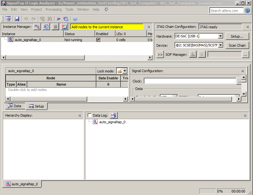
- Open the SignalTap II window by selecting File>New , then Choose SignalTap II Logic Analyzer File and click OK.
- In the window whch opens, select File>save as and save as counter.stp, then click yes in the dialog box asking if this is the active signal tap file.
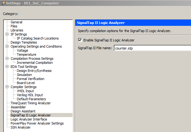
-- Note: If you want to disable this file from the project, or to disable SignalTap from the project, go to Assignments>Settings . In the category list, select SignalTap II Logic Analyzer , bringing up this window. To turn off the analyzer, uncheck Enable SignalTap II Logic Analyzer .
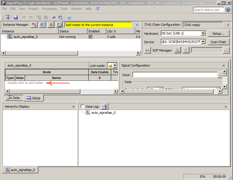
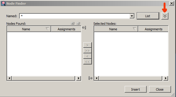
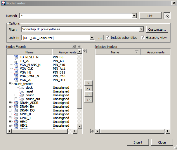
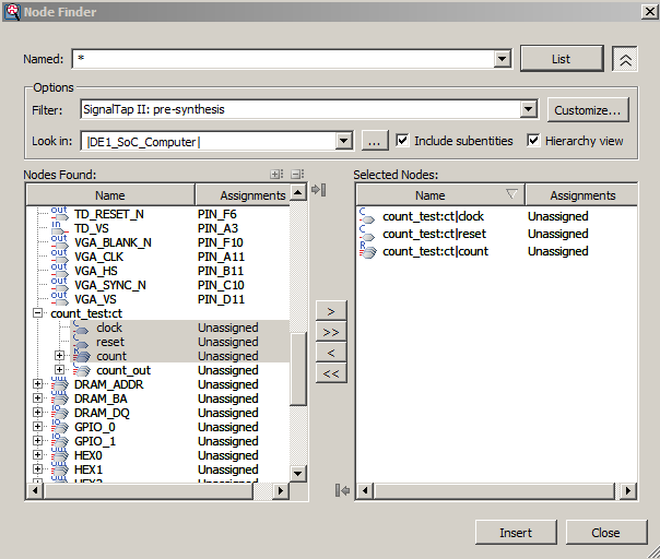
- Now we need to connect SignalTap to the counter and supply trigger condtions so that SignalTap knows which event to detect in order to store waveforms. Double-click in the area labeled Double-click to add nodes , bringing up the Node Finder window, and click on the expand button (marked with an arrow) to show search options. In the Filter field, select SignalTap II: pre-synthesis , and for the Look in field select |DE1_SOC_computer| . Click the List button in the upper right corner. This will now display all the nodes that can be probed in the project. Choose signals to probe in the left panel and use the > button to select them into the right panel. Click the Insert button to insert the selected nodes, then Close button to close the Node Finder window.
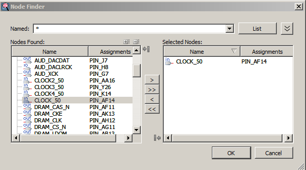
- Now we need to specify what clock is going to run the SignalTap module that will be instantiated within our design. To do this, in the Clock box of the Signal Configuration pane of the SignalTap window, click ... , which will again bring up the Node Finder window. Select List to display all the nodes that can be added as the clock, and then double-click CLOCK_50. Click OK .
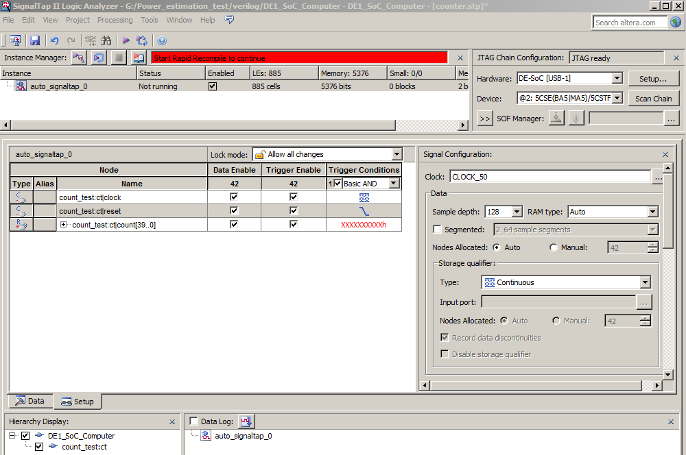
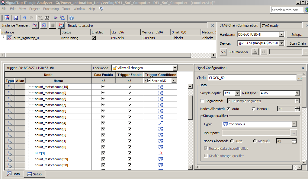
- With the Setup tab (left side, 2/3 way down the window) of the SignalTap window still selected, select the checkbox in the Trigger Conditions column. In the dropdown menu at the top of this column, select Basic AND . Right-click on the Trigger Conditions cell corresponding to the node reset and select falling edge. Now, the trigger for running the Logic Analyzer will be when key[0] on the board is released. Note that you can right-click on the Trigger Conditions cell of any of the nodes being probed and select the trigger condition from a number of choices. The actual trigger condition will be true when the logical AND of all these conditions is satisfied. For now, just keep the trigger condition as falling edge of reset and the others set to their default value, Don’t Care .
- Make sure the FPGA hardware is communication is correct using the Setup... button (upper right corner). If the USB blaster is not configured you may get an warning like invalid JTAG. Compile the project (including SignalTap) and program the board.
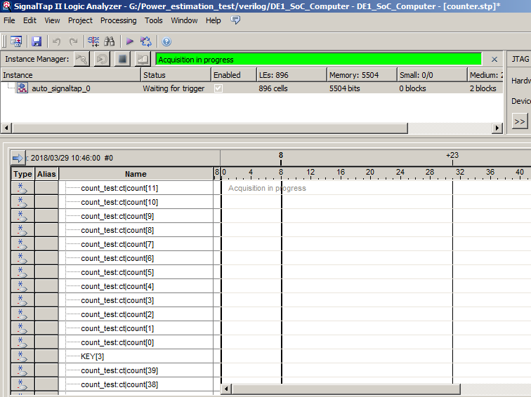
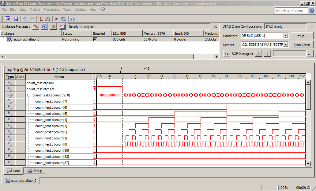
- Select the Data tab (left side 2/3 down the window), then choose on processing>Run Analysis.
The interface should wait until you press key[0] (reset), then show you waveforms.
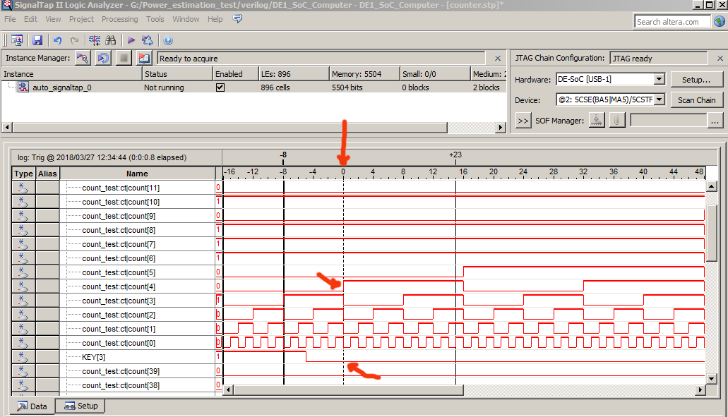
- Modifying the trigger condition to wait for a rising edge on bit 4 of the counter and key[0] low, results in this data.
The trigger conditions at time zero are marked with arrows.
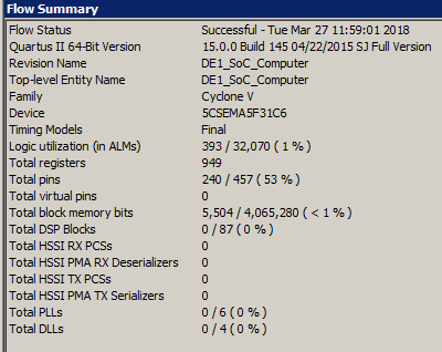
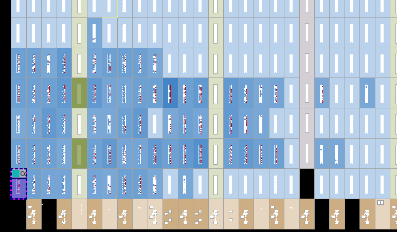
- A look at the synthesis results will show you that some M10k memory is used. In the Signal Configuration pane of the SignalTap II window, in the Sample depth dropdown menu of the Data pane, you can choose the number of samples stored. This option allows you to specify how many samples will be taken around the triggers in your design. If you require many samples to debug your design, select a larger sample depth. Note, however, that if the sample depth selected is too large, there might not be enough room on the board to hold your design and the design will not compile. If this happens, try reducing the sample depth. The chip planner interface shows that quite a lot of logic was built, including using two M10k blocks, to support SignalTap. The design for the counter is 17 ALMs. With SignalTap the design is 390 ALMs. But as the actual design gets bigger, the SignalTap size will not grow porportionally.
- Sometimes a design you create will have wires in it that the Quartus compiler will optimize away. You can force Quartus to keep the wires for probing by SignalTap by including the directive /*synthesis keep*/ on the line where you declare a signal. For example,
wire abc /*synthesis keep*/;
SignalProbe
A scheme for bring signals out of the FPGA with very little (or no) recompile.
Tools > SignalProbe Pins...
Chapter 13 of Quartus Prime Handbook Vol 3
https://www.altera.com/en_US/pdfs/literature/hb/qts/qts_qii53008.pdf
https://www.altera.com/support/support-resources/software/debugging.html
https://www.youtube.com/watch?v=20WwtqaA1dY
Bus Analyser Tool Kit
Gain visibility into your Qsys interconnect based system.
Tools > System Debugging Tools > Bus analyzer
http://www.alterawiki.com/wiki/Bus_Analyzer_Toolkit
On-chip Debugging Design Examples
https://www.altera.com/support/support-resources/design-examples/design-software/on-chip-debugging.html
Using TimeQuest Timing Analyzer (Quartus Prime)
Quartus Prime Standard Edition Handbook Volume 3: Verification Chapters 6 and 7
Quartus Prime Standard Edition Handbook Volume 1: Design and Synthesis
Quartus Prime Introduction Using Verilog Designs
Copyright Cornell University,
January 31, 2019