Hardware
There are two main systems which connect the keyboard and the PIC32: the LEDs and the key matrix. Wherever possible, we use ribbon cables and pin headers to connect subsystems together which helps keep things organized and allow us to remove the subsystem to work on it. We tried to preserve the exterior appearance as much as possible, and only show the TFT display, reset button, and LEDs which are what the user interfaces with. Every other component is placed in the keyboard case and secured with hot glue or electrical tape.
Keyboard
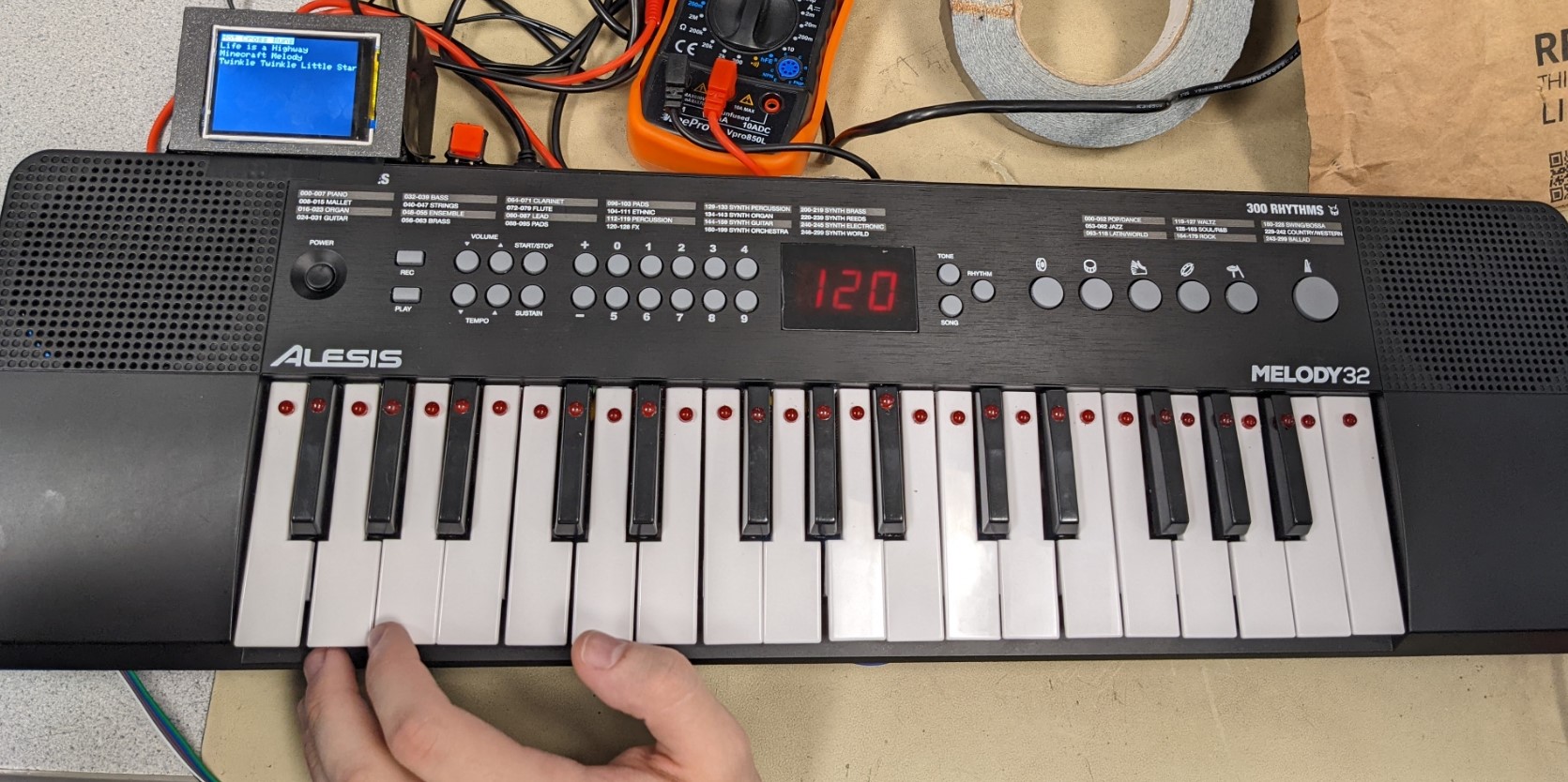
The keyboard we used for this project is the Alesis Melody 32. We chose it because it had 32 keys which would work with the limited number of GPIO pins available on the PIC32, it had a relatively low price of $50, and it was bigger than the alternative options which allows for easier wiring. The keyboard could also be powered over USB or with AA batteries giving us options for how we wanted to power the system even though we ended up only powering it over USB. The Alesis Melody 32 proved to be a good choice because it was easily to disassemble and reassemble, the wires were well managed, and there was a large amount of empty space in the case.We did have to remove some internal plastic supports to have room for wires and perf boards but did not notice any structural issues even after doing this. We were unfortunately not able to seal the keyboard because the wires connected to the headers on the PIC32 board were too tall, but if we bent the pins or soldered the wires directly to the board we believe there would be enough room to seal the keyboard.
LEDs
There are 32 LEDs in the project, one embedded into every key. To mount the LEDs, we cut away some plastic ribbing in the center of each key, drilled a hole for the LED, and secured it with hot glue. The LEDs needed to be wired to the shift registers so we soldered wires to each of the leads and covered the connection with heat shrink. To make the wires more manageable, we took eight positive or negative wires at a time and twisted them to make a bundle. We used two perf boards to handle connecting all the components for this system. One board had 32 470Ω resistors with one lead connected to ground. The other board had four of our SN74HC595 shift registers. We could then connect each of the negative leads of the LEDs to a resistor on the first board and each of the positive leads to the appropriate output on the second board. We also soldered a 6-pin ribbon cable to the board with the shift registers to easily connect the SRCLK, RCLK, and four DATA lines to the microcontroller development board.


Keyboard Matrix
In taking apart the keyboard, we found that it was already using a 5 column and 8 row matrix to detect keypresses so rather than wire our own matrix, we traced the wires back from the keys to the keyboard motherboard and soldered ribbon cables to the underside of the connectors. The matrix works on an active low system so each of the 13 lines is held high and the microcontroller on the keyboard rapidly cycles through the 5 column lines, pulling one of them low at a time. It then checks to see if any of the rows also went low. Each of the keys is a switch that uniquely connects a column to a row so if a key is pressed and the column it is connected to is pulled low, the row it is connected to will also be pulled low. The microcontroller on the keyboard can detect when a row is pulled low and since it also knows which column was low at that time, it can determine which key was pressed. To receive input on the PIC32 side of the system, the method is slightly different. Since we do not determine when one of the columns is pulled low, we had to read the voltage level on both the columns and the rows. We initially planned to use the change notification feature of the GPIO pins to determine when a column is pulled low and then read the rows in the change notification interrupt so we connected the column wires to the available pins on port B of the microcontroller and used port Z of the port expanded for the rows. However, we found that it took to long to enter the interrupt and that by the time the port expander read the row data, the column data was no longer valid. Instead we just read the two ports in subsequent operations without the use of interrupts so it is no longer important that the columns are connected to the specific pins on port B.

TFT Display
To mount the TFT display, we modeled and 3D printed an enclosure which we could attach to the side of the keyboard and route a ribbon cable through. We initially planned on mounting the display on the back, in the middle of the keyboard and soldered headers to a long ribbon cable to connect the TFT to the PIC32 board. However, we found that the display did not work properly with longer cables, so we had to settle for using a shorter cable and moved the display enclosure to the left side of the keyboard, closer to where the PIC32 board was mounted.


PIC32 Big Board
The PIC32 big board had many wires connecting it to the other systems in the keyboard. It was mounted on the left side of the lower case of the keyboard. We had to drill two more holes into the lower case to add external connections to the board. The first hole was for the DC power jack and the second was for an external reset switch which we taped to the TFT display enclosure and soldered to the leads of the existing reset switch on the board.