An Introduction top
"A glove embedded with accelerometers to play a hand motion-controlled chess game"
project soundbyte
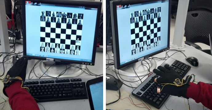
For our ECE 4760 final project, our team designed and built a system with the ability to play the game of chess using embedded gloves. Each player wears a glove (there are two gloves for two players) and uses hand-motions to play a chess application. The chess board graphical user interface is generated using MATLAB, which receives information from the player’s gloves through a serial connection with the microcontroller, and updates the game appropriately. As such, when a player tilts his hand in a certain direction, the cursor on the computer screen moves accordingly. Since the glove also has contact sensors in the form of copper strips on both the thumb and pointer finger, pressing these two fingers together simulates picking up or dropping a piece at the location of the cursor. The goal of our project was to simulate the physical motions involved in playing chess without the need for a physical chess set.
High Level Design top
Rationale and Source of Our Project Idea
Our team explored various ideas about how to revolutionize a game of computer chess. Playing chess with a simple computer mouse can simply be boring, and does not have the same feel as playing a game with a real, physical chess set. As such, we came upon the idea to make a computer chess game that more closely simulates a physical chess game and further blur the distinction between the real and the virtual. As such, our vision was to eliminate the computer mouse and replace it with in-air hand motion. As technology advances, the computer mouse is becoming less and less standard. For example, touchscreens have recently become popular because it completely eliminates the need for computer mouse. However, much like in futuristic movies like the Minority Report, the idea of being able to control mouse movement with in-air hand motion is something that is not so common in current consumer technology. We do note that past projects have had a similar idea, but our team wanted to build on this idea with our own spin, and apply this technology specifically to a game of chess.
Background Math
Since we are dealing with accelerometers, we must remind ourselves of Newton’s equations of motion. Newton’s three famous equations are taught to virtually every student of elementary classical mechanics. These equations are:
- v = u + at
- s = ut + (1/2)at^2
- v^2 = u^2 + 2as
The first and second equations above are of particular interest to us. We need the first equation in order to identify the velocity at which the cursor should move based on the reading of the accelerometer from a tilt of the hand. Likewise, the second equation is needed to determine the relative displacement. In short, our hand motions/tilts result in variable a-values (acceleration), and these equations help us translate the motions/tilts to cursor speed and location on the computer screen.
Logical Structure
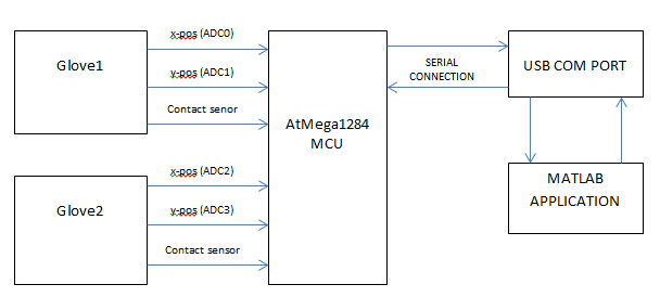
At a high level, the system has three main blocks. At a high level, the system has three main blocks: the embedded gloves, the microcontroller code, and the MATLAB GUI. Each glove is embedded with a three-axis accelerometer and fitted with copper strips around the pointer finger and thumb to act as contact sensors. For each accelerometer, only the x and y axis is used. A hand-tilt forward corresponds to the positive y-direction, while a hand tilt backwards corresponds to the negative y-direction. Likewise, a tilt to the right corresponds to the positive x-direction while a tilt to the left corresponds to the negative x-direction.
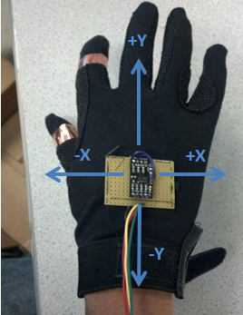
Embedded glove with labeled axis
The contact sensors simulate a button click, where pressing the pointer finger and thumb together creates an active-low signal that is sent to the Atmega1284 microcontroller. The x-data and y-data from the accelerometer are sent to an analog-to-digital converter in the microcontroller. The microcontroller transforms this information received from the gloves to update the cursor coordinates. The microcontroller also handles the state of the chess game, maintaining and managing a wide array of state information needed to update the game. The microcontroller continuously creates packets containing the cursor coordinates and other state data and sends them off to a MATLAB application using serial communication. MATLAB continuously requests these packets and parses them to decide how to render and update the graphical user interface that represents the chess board.
High-Level Diagram
Hardware and Software Tradeoffs
A large portion of our project revolved around the software component since all the chess algorithms and serial communication were written in software. Since we only had to sample the analog-to-digital converter once every millisecond, it also was not necessary to have any additional hardware for that purpose. However, we did opt for hardware debouncing when it came to our push-buttons (used to reset the game) and contact sensors (used to simulate a button click) to avoid having to implement a software debounce state machine similar to what we dealt with in previous laboratory assignments. Within the software component, however, there was a tradeoff between what functionality was written in MATLAB and what was written in C. Since this is designated a microcontroller project, we chose to have the microcontroller, not MATLAB, maintain the entirety of the state of the game. MATLAB’s purpose was to render and redraw the GUI according to the information it received from the C portion, although this proved to be quite extensive as well.
Standards
Our initial approach to interfacing the microcontroller with the CPU involved either using the PS2 or USB HID protocol, and hence we expected to abide by the PS2 standard or USB standard and specifications. However, we found that our task would be made simpler by foregoing these standards and communicating with the PC using a serial connection instead. We thought it would be most effective to define our own packet structure (specific to our chess application) for serial communication, and hence did not use any standard in that respect.
Relevant Copyrights
To help create the MATLAB graphical user interface, we consulted an open source MATLAB project found on the MATLAB Central File Exchange site. The project, called Chess Master, was written by Suleman Shafqat. We modified the image files provided in his program to construct our own chess piece images.
To help create certain parts of our chess algorithms for the C portion of our code, we consulted two old ECE 4760 final projects. One of these projects was called “Touchscreen Chess,” and was designed by Samiul Nur and Caspar Valk in Spring 2012. Their team also built off an older project called “Remote Chess,” designed by Erik Jarva and William Baughman in Spring 2008. To build our website, we adapted a Cornell template used by Adam Papamarcos and Kerran Flanagan, another project team that that developed “Human Tetris” in Spring 2010. Links to these references are provided in the appendices below. Further discussions of intellectual property and copyright laws will be discussed in later sections.
Hardware top
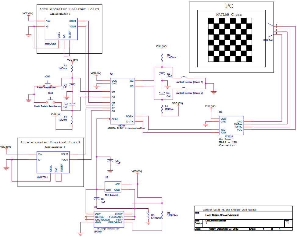
The most important hardware we used are the 3-axis accelerometers. Each accelerometer has an on-chip voltage regulator which converts the 5V Vcc to about 3.3V. We built our own voltage regulator circuit to provide a 3.3V source to the analog reference on the ADC. This was to improve sensitivity to voltage changes by using the whole 0xff range on ADCH. We also connected copper strips around the thumb and index finger to be used as a switch and for picking up pieces. We opted for hardware debouncing of the contact sensors to allow the mcu more time to perform complex chess algorithms. Hardware debouncing was done using an RC circuit to smoothen the transition of a switch. We also have a switch on the board that can be used to reset the chess game. Each accelerometer has four color-coded connections to the mcu. A red wire connects to 5V Vcc, a black wire to ground, a yellow wire to x-channel of the ADC (A0 for player 1, A2 for player 2) and a green wire to the y channel (A1 for player 1, A3 for player 2) of the ADC.
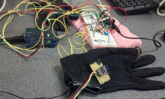
Glove and target board wired up!
Trials & Tests
The first test was to connect header pins to the accelerometer, build an accelerometer circuit on a breadboard and measure voltage deflections on an oscilloscope. The data sheet provided by the vendor was rather confusing so we used trial and error testing to determine the connections. After the first round of tests failed, we discovered that we soldered the headers to the accelerometers the wrong way so there was no contact between the breadboard and the accelerometer. We had to use a dremel tool to cut the headers, take them out and resolder. After more trial and testing and with a bit of prior knowledge of accelerometers, we discovered that the ‘sleep’ pin on the accelerometer had to be connected to Vcc, and that it only worked when the ‘g select’ pin we connected to was grounded. After the accelerometer gave the correct voltage deflections on the oscilloscope, we then used the ADC to sample the accelerometer at horizontal position to find what values of ADCH corresponded to 0g. It was discovered that, of the four outputs tested (x and y outputs of two accelerometers), the 0g value was between 131 and 142. As such, to make the glove resistant to noise we only considered ADCH values outside the range of [131,142] as valid accelerations. We also tested the debouncing
Software top
The C Portion
Chess State Diagram
Chess State Diagram
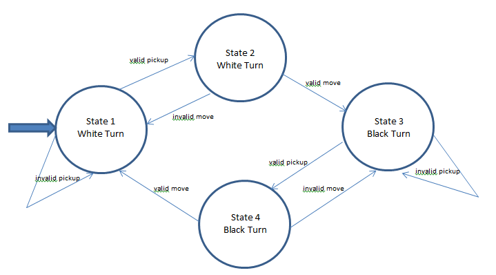
Our program has a 4-state state machine. After initialization, the program defaults to state 1. In this state, the program waits for player 1 to pick up a white chess piece. If and only if player 1 clicks in a square on the board occupied by a white piece, the state machine transitions to state 2. In state 2, the program waits for a valid move to be made. If an invalid move is made, the state machine returns to state 1. If a valid move is made, the state machine transitions to state 3. State 3 is the start of player 2’s turn (Black pieces). If a click is made on a square with a black piece, the state machine transitions to state 4. In state 4, the program waits for a click on a square to initiate a move. If an invalid move is made, the state machine returns to state 3 so player 2 can attempt to play again. On the other hand, a valid move would see the state machine transition to state 1 so player 1 can play. This state machine keeps looping until the game ends in a checkmate or a button is pushed to reset the game. Resetting the game returns the program to state 1.
Chess Algorithm
The central part of our project was the chess algorithm. We obtained the core of this algorithm from ‘Touch Screen Chess’ project. This project also referenced an earlier project called ‘Remote Chess’. The most important function we obtained was the IsMovePossible() function. This contains the legal moves every chess piece is allowed to make. The code works by initializing an 8x8 character array (tileBoard) and initializing the positions of the white pieces with the value ‘1’, the positions of the black pieces with the value ‘2’ and empty tiles with the value ‘0’. Each piece had a struct which kept track of the location on the board in row order from 0 to 63. We decided that there didn’t need to be a different struct for each piece, so we created our own generic struct Piece_t for different pieces. This way, we were able to make an 8x8 array of pointers to Piece_t. As such, in order to find the piece located in a square, we only had to dereference the pointer at that location instead of doing a comparison with possibly every single piece on the board. An empty square simply has a pointer to NULL. After a move is made, both the tileBoard and the pointer array are adjusted to reflect this change. We also added bounds checking in the IsMovePossible() function because we reasoned that we would need it if we ended up writing an AI for playing chess in addition to our project. We wrote an inCheck function. This function basically goes through the board to find if the king in question is in check and returns a 1 if the king is in check and a 0 otherwise. The inCheck function also generates ‘tempUnsafeSquares’ which are squares into which a piece would have to be placed to move the king out of check.We also added ‘pinning’ to the IsMovePossible() code. Basically, if a player’s move will put his king in check, it is an invalid move. We temporarily make this move in IsMovePossible() and call the function inCheck to see if this move will place the king in check. After this we return the tileBoard and piece_t pointer array to its state at the time IsMovePossible() is called. This function then goes ahead to check the valid moves if the there was no ‘pinning’. Checkmate: The game of chess ends in a checkmate or a stalemate. A checkmate occurs when the king is in check and no legal move can take the king out of check. This function first checks to see if the king is inCheck. This time however, we set a flag for copying the ‘tempunsafeSquares’ array generated in inCheck() function into unsafeSquares. This is used to determine the positions a king’s pieces would have to move to in order to take the king out of check. If no piece can move into this square and the king can’t move out of check, then it is a checkmate.
Hand Tilt Sensing
Position sensing is done with the use of accelerometers as mentioned earlier. We set up the ADC to use external voltage reference of 3.3V that we obtain from our breadboard voltage regulator. We set up ADMUX initially by writing a 1 to the left adjust bit. This implies that we initially sample from channel A0 (ADC0). We use an input clock frequency of 125kHz to ensure maximum resolution although we only require the top 8 bits. Since the ADC takes 13 cycles to produce a valid output, we are required to wait at least 0.104ms after we start conversion to read the output. We actually sample the ADC once every millisecond. A timer 1 ISR interrupts every millisecond to ensure a constant sampling interval. In the ISR, we flip the LSB of ADMUX. This changes from channel ADC0 to ADC1 for player 1 and from channel ADC2 to ADC3 for player 2. The idea is that, within 2ms the tilt of your hand doesn’t change much so we essentially read corresponding y axis and x-axis voltage deflections. When a changePlayer() function is called, we flip the 2nd LSB which toggles between the first two channels and the next two for a player switch. At the start of each player’s turn, we set the variable xy to 0 to ensure that we start by sampling in the x direction. This variable changes to 1 when the y-axis is to be sampled. The variable ‘xy’ is flipped every time the ADMUX changes in a player’s turn.
Contact Sensing
Contact sensing is done with the use of copper strips wired onto the gloves. When they are joined, an IO port pin changes from Vcc to ground which generates an interrupt. External Interrupt 0 (INT0 on D2) is used for player 1 and External Interrupt 1 (INT1 on D3) are used for player 1 and player 2 respectively. When it’s player 1’s turn, we mask the interrupt from player 2 and vice versa. When a click is made, a check is made in C to determine if it was a valid click. In state 1 of the state machine, a valid click is made is player 1 tries to pick up a white piece. In state 2, a valid click is made if player 1 attempted to make a valid move. The same holds true for player 2 with state 3 and state 4 behaving like state 1 and 2 respectively. Debouncing is done using an RC circuit to smoothen the rise and fall of a toggling pin.
Switches
Our system has one switch connected to port C0 and another connected to port B0. The switch connected to B0 is used to reset the game. The switch connected to C0 was intended to be used to toggle between 2-player mode and computer mode, in case we were able to write an AI for computer mode. The switches are debounced using the same kind of RC circuits used for the contact sensors. When a switch is pressed, a PC interrupt is generated. Since in testing, such an interrupt was generated on any toggle of a port pin, we needed some code in the ISR to check the state of the pin to ensure that the interrupt is generated exactly once when a switch is pressed.
The MATLAB Portion
In order to render the GUI on MATLAB, we defined a set of 13 different packet types in order to quickly and efficiently convey the information MATLAB needed to render the chess game. The packet structure was defined such that MATLAB would not have to do any processing of chess game itself, it would be provided all of the information needed to render the game. Based on what information MATLAB parses from the serial packets, the GUI is able to manipulate all of the chess pieces and simulate a player playing a real chess game. In order to efficiently send the data from the microcontroller to MATLAB, we used a serial connection and defined a packet structure so the packets could be easily constructed by the microcontroller and the could be packets could be easily parsed by MATLAB. The microcontroller constructs the packets by putting together 5 two-byte ints and sending them over the serial connection. The way the ints are used to convey information is as follows:
| Int 1 | Int 2 | Int 3 | Int 4 | Int 5 |
|---|---|---|---|---|
| Type ID | X Position | Y Position | Selected Piece | Previous Location or Captured Piece |
The packet structure we used is as follows:
| Packet Type | Type ID | Description |
|---|---|---|
| Reset | 0 | Resets the chess GUI |
| Move Piece | 1 | Freely move the currently selected piece |
| (Reserved) | 2 | Reserved in case we needed to add more message types |
| Error: Pinned | 3 | Display pinned error, drop currently selected piece in original location |
| Error: Invalid Move | 4 | Display invalid move error, drop current piece in original location |
| Drop Piece | 5 | Drop the current piece in the square the cursor is over |
| Capture Piece | 6 | Drop piece as described above, and remove piece specified in packet |
| Castle | 7 | Castle the currently selected king |
| Move Cursor(in Check) | 8 | Freely move cursor while displaying check message |
| Move Piece(in Check) | 9 | Freely move piece while displaying check message |
| (Reserved) | 10 | Reserved in case we needed to add more message types |
| Checkmate | 11 | Freely move cursor while displaying which player wins |
| Queening | 12 | Drop currently selected pawn in final row and turn pawn into queen |
| (Reserved) | 13 | Reserved in case we need to add more message types |
| Move Cursor | 14 | Freely move cursor |
| Pick Up Piece | 15 | "Pick up" current piece by setting as current piece |
Serial Packet
Not every packet type uses every single byte that is sent over the serial connection. All 10 bytes are sent every time in order to maintain uniformity in sending the data over the serial connection and reading out of the serial port. We determined that the amount of extra time it takes to send a the unused ints in certain packets is significantly smaller than the time it takes MATLAB to render the GUI. Thus each time a packet is sent, all 10 bytes are sent and MATLAB reads all of them in, but it may not use all of them. Each packet (except the Reset packet) uses the second and third ints to specify where the cursor should be positioned. The following describes what each packet does and if and how each packet uses the other available bytes:
Reset
The Reset packet only needs to use the first int (type ID). This is because MATLAB doesn’t need any additional information to restart a game. When a game restarts, the cursor is in the middle of the screen and all of the pieces are in their starting position
Move Piece
This packet is what allows a user to freely pick up and drag around a piece. Because we do not put any constraints on where the piece can be rendered while it is in free movement, the microcontroller only needs to notify MATLAB that the piece is being freely moved around and the x and y location of the cursor. As the piece is being moved around, the piece is centered on the cursor to make the user’s experience of “picking up” and moving the piece with his or her hand seem more natural.
Error Packets
The Pinned Piece Invalid Move error packets each use all ints except the 4th int. When a player is moving around a piece, MATLAB already knows which piece was picked up, and so that information does not need to be sent by the microcontroller. However, MATLAB does not store the original location of a piece when it gets picked up, so that information does need to be sent by the microcontroller. To encode this, the column that the piece should be placed in gets encoded in the first 4 bits of the last int of the packet, and the row in the second 4 bits of the last int in the packet. The functionality in the two error packets is identical except for the error message that gets displayed for the user. The Pinned Piece packet tells the user that a move was invalid because their piece was pinned, whereas the Invalid Move packet is a more generic packet that notifies the user they made an incorrect move. Some chess players do not always see where and how their pieces are pinned, so we included the extra packet type to make a more comprehensive user experience.
Drop Piece
This packet drops the selected piece in the square the cursor is over. Because MATLAB keeps track of the selected piece from packet to packet, the microcontroller only needs to send out the type ID and the x and y location for this packet. MATLAB determines which individual square the cursor is over based on the x and y location, and MATLAB drops the piece in the square. By dropping a piece in this way, a user can drop the piece anywhere in the square and the system will still correctly recognize the ending location of the piece.
Capture Piece
This Capture Piece packet shows the selected piece capturing a piece specified in this packet. This packet simply places the currently selected piece in the square the cursor is over, and removes the captured piece from the game. Removing a piece from the game consists of setting the ‘Visible’ property of the image handle to be ‘off’ so it is no longer displayed on the board. By setting a piece to be invisible instead of deleting the handle to the object, we significantly speed up the reset function, which will be discussed later.
Castle
The Castle packet has a similar encoding and functionality as the error packet. The fourth int in the packet specifies the piece identifier of the rook that is involved in the castle, and the 5 int contains the location to drop the rook in. When a player is attempting to castle, the king is the currently selected piece so that information does not need to be conveyed by the microcontroller. The castling functionality works by dropping the currently selected piece in the square the cursor is over, and then placing the rook specified by the piece identifier in the location specified by extracting the row and location from the fifth int in the packet.
Move Cursor(in Check)
This is derived from the basic Move Cursor packet. The only difference between this packet and the Move Cursor packet is that this packet is sent when the just the cursor is being moved around on the turn of a player who is in check. When MATLAB receives this packet, a message is displayed in the GUI that tells the player that they are in check. Aside from these differences, all of the other functionality and packet data usage is the same.
Move Piece (in Check)
This is derived from the basic Move Piece packet in the same way that Move Cursor (in Check) is derived from the basic Move Cursor packet. This packet is sent as a player that is in check is moving a piece around the board, and this packet signals to MATLAB to display a message in the GUI that tells the player that they are in check. Aside from these differences, all other functionality and packet data usage is the same as in Move Piece.
Checkmate
In Chess, a checkmate is the victory condition for a player. A checkmate occurs if a player is in check at the beginning of their turn and they are unable to make a valid move that will bring them out of check. Similarly to the Draw packet, the only information needed to convey this from the microcontroller to MATLAB is the first three int of the packet, which contain the type ID and the cursor location. After a checkmate occurs, a player can still move around the cursor, but no piece can be picked up.
Queening
The last advanced chess rule that was included in this project was the act of queening a pawn. If a pawn advances all the way to its final row, the pawn is promoted to a queen. This move does not take an extra turn-it happens as soon as the pawn reaches the final row. Prior to the promotion, the pawn is already the selected piece, so the microcontroller only needs to specify the type ID and the location to drop the piece into in order to display a pawn getting queened.
Move Cursor
The Move Cursor packet is used when a user is moving their cursor around the board without having picked up a piece yet. The Move Cursor packet simply updates the cursor location and displays a message at the top of the GUI that states whose turn it is.
Pick Up Piece
This packet sets the internal MATLAB variable for which piece is the currently selected piece. Regardless of the action they take - move, capture, castling, issuing an invalid move - the primary piece involved in the action has to be the piece the player has picked up. This packet also centers the newly selected piece on the cursor in preparation for the next packet that will be sent, which will either be a Move Piece or a Move Piece (in Check) packet. By having a separate packet that updates the MATLAB internal variable, we avoid having to send and parse the piece identifier in each packet. Not having to send a piece identifier with each packet decreases the room for error and time it takes to process each packet in MATLAB.
MATLAB Graphical User Interface
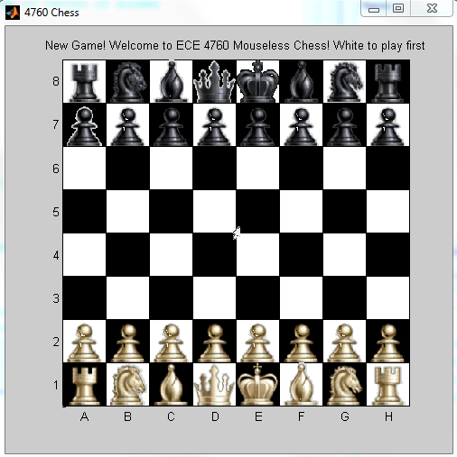
Chess board GUI
Initializing the Board
The GUI function is responsible for initializing the chess GUI. It begins by creating a rectangle with dimensions 480x480 pixels. The dimensions are chosen as such because the chess pieces to be used each have dimensions 60x60. As a result, an 8x8 chess board with squares of size 60 will result in a board of size 480. The individual squares of the chess board are created using a double for-loop that alternates drawing white squares and black squares of size 60 across the board. The x-axis is relabeled with characters A-H and the y-axis is relabeled with characters 1-8. The axis ticks are spaced appropriately, resulting in a properly labeled chess board. The pieces for the chess board are created using image files contained in the “pieces” folder. We pass these images to handles for each individual piece on the chess board at the initial coordinates we pass through our drawPiece() function. We call drawPiece for all 32 pieces on the board to draw all pieces on the board as desired. One important thing to note, however, is that the original images in the pieces folder have either a black background or a white background. This is significant because if a pawn image with a black background (originally in a black square) moves into a white square, then that square would seem to have a black background, creating an illusion of three consecutive black squares. To counteract this issue, we carefully and meticulously adjusted the alpha data for each image to make the image backgrounds transparent for each type of piece. It is also worth noting that our game cursor is actually an image of a cursor with a transparent background, not the actual computer cursor itself.
Rendering Piece Movement and Placement
Once the GUI has been initialized, we will want to continuously update it as it receives information from the microcontroller through the serial connection. MATLAB will parse the packets it receives via the parsepacket function, and update the GUI accordingly. If the mcu wants to move a piece, it will send x and y coordinates. The GUI will then adjust the xdata and ydata of the piece image and re-render the chess board via the move() function. Thus, to simulate dragging a piece, the move() function is called continously (several times a second). Moving the cursor is handled in the same way. When a piece has been moved to a location and the microcontroller wants to drop the piece in the square, an additional step is required to ensure the piece is correctly fit into the size of the square. The x and y coordinates are cast into integers, divided by 60, and then immediately multiplied by 60. This ensures that the new x and y coordinates at which the image will be dropped will be multiples of 60. For example, say the program has moved a piece to coordinates (134, 200) and now wants to drop the piece. Placing the image at these coordinates will result in the chess board rendering a piece in between two or more squares. With the method described above, the new x and y coordinates will be (120,180) and the piece will be correctly rendered at position C4. If the piece is dropped at a location where a piece already exists, the GUI assumes the piece originally at the location has been captured, and simply sets its “Visible” property to “Off.” Our rationale for rendering image movements in this fashion are for the sake of efficiency. Re-drawing the board and images and stacking images on images is wasteful and will slow the program down, especially after it has been running for a long-enough period of time. Thus we circumvent this issue by not having to redraw any images and simply shifting the images around on the GUI.
Rendering Messages
Every game needs a method of displaying messages to give feedback to the players, and our team chose to display such messages through the use of a title string above the chess board GUI. Depending on the state of the game (communicated to MATLAB through packets from the mcu), the titlestring will be updated to notify the player if a move is invalid, if a player is in check, which piece has been captured, etc. The titlestring is a global variable, and the title itself is only updated when a specific packet is parsed and MATLAB updates the variable titlestring.
Rendering Reset
For many games, being able to reset the game is an important functionality. It allows for another instance of a chess game without closing and restarting the program. To reset the GUI, it is necessary to return all piece images to their original location and make all captured pieces visible. This is done by setting the XData and YData image properties to the original coordinates and setting the Visible property to On for each image. Recall that when a piece is captured, it’s visibility is simply turned off. There are always 32 pieces on the chess board GUI. The players simply don’t always see them all.
Trials & Tests
When it came to testing software, each team member specialized in a certain sector of the project with specifications for integration in the future. As a result, testing went from the roots and grew up to the final design. Each subsection was tested independently, added to a larger subsection, and tested again. This method of testing and integration took place in a few major subsections, as described below.
The Chess Algorithm
The algorithms required for chess are plentiful and complicated. A UART test program was written for testing purposes. An 8x8 integer matrix was printed to the console with each move, with a 1 representing a white piece and a 2 representing a black piece. Commands would then be input into the PuTTy console to simulate chess moves. When the mcu receives meaningful commands, the ISRs for clicking are called as functions to simulate a click. The commands were in the form “x y” where x and y are integer indices of the tileBoard array.As a result, it was possible to test individual functions independent of a GUI and observe if the output that resulted was indeed the desired behavior. We managed to test many functions including simulating four real-life checkmate situations which all worked in testing.
The MATLAB Application
None of our team members had extensive experience with MATLAB. In fact, we were far more comfortable creating a Java application, a language more suited for designing GUIs. However, it was far simpler to interface with MATLAB through a serial connection, so we opted for that direction instead. As a consequence, developing the graphical user interface to represent the chess board took a large amount of research, trial, and error. We began by first creating the initial chess board and then placing images at desired locations. This process took several trials as we toyed with the possible built-in MATLAB functions that we believed may result in the desired behavior. One major issue that arised was the fact that the images to represent the pieces on the board had white and black backgrounds. When dragging such pieces across the board, we needed the backgrounds of each piece to be transparent. Much research was done in this regard. First, we tried to import a transparent image from an online editor. When that proved unsuccessful, we tried to import a transparent image from Adobe Photoshop. Once it was discovered that this approach would not work, we proceeded to meticulously encode the alpha values of each pixel to create transparent images of each type of piece. This took much trial and error, but was eventually a success. Another issue we encountered dealt with setting the cursor location. We had initially planned to set the pointer location of the actual computer cursor manually, but had difficulty syncing the coordinates of the overall screen with the MATLAB window. Thus, we proceeded to create our own cursor image within the GUI and update that image to act as a cursor. It is worth noting that this slightly slows down the processing within MATLAB since this is an image that needs to be continuously rendered. Each function needed to update the GUI was tested independently through use of the command window. That is, a function would be run and then observed to see if the desired behavior had resulted. For example, the reset functionality was tested by first calling a few move and drop functions (after they were independently tested) and then calling the resetboard() function in the command window.
The Serial Connection: Integrating the MCU with MATLAB
The MATLAB code to establish the serial connection with the microcontroller was carried over from a previous project by one of our team members, and thus required minimal testing to ensure functionality. More relevant, however, was ensuring that the connection could be used to properly create, send, and parse packets. To test that MATLAB would be able to parse the packets correctly, a program called Virtual Null Modem was downloaded and installed to create a virtual serial connection to specified COM ports. Packets were then created in the MATLAB command window and sent to the port to be buffered and then parsed via the parsepacket() function. Packets with each message type were individually tested in this manner to ensure that the parsing of each packet resulted in a correct rendering of the GUI. Meanwhile, on the MCU side, packets were created with x and y coordinates and printed to the PuTTy console using UART. This served to test if the hand tilts with the glove resulted in the desired behavior. Convinced, that each side was working well on its own, we connected the MCU to the MATLAB application and began testing. It was quickly discovered that the sending of packets was not working as we originally expected. In our design, the MCU would repeatedly send packets to MATLAB every 20 milliseconds, but this caused MATLAB’s buffer to overflow and cause undesirable behavior. We thus shifted our design to allow MATLAB to request packets, scan them, and then move on to parse them. To scan the packets using fscanf, we also had to change our approach for encoding the packets. Instead of using the putchar method in our C code and bit-packing to create a 7 byte packet, we used the fprintf method and simply input 6 integers to be read. This approach allowed MATLAB to correctly read the packets without drastic changes in code. Once the connection was complete, our method of testing shifted to full-scale integration and we began playing the game with the gloves and observing the changes on the GUI. This, of course, led to the discovery of several bugs related to timing, positioning, and holes in the chess algorithm and packet parser. With careful debugging, almost all bugs and unexpected behavior have been eliminated.
Results top
Speed of Execution
The cursor movement is quite fluid- as fluid as it could be with MATLAB rendering the image. After performing some tests we discovered that MATLAB takes about 40ms to render the image of the cursor. As a result, even though we intended to transmit data through UART every 20ms, we were limited by the 40ms it takes MATLAB to render the image of the cursor. While moving a piece, it might take as many as 80ms for MATLAB to render both the cursor and the piece on the screen. This causes a slight flicker in the image of the piece. We suspect that rendering pieces takes more than 40ms. However, slowing down the delay in the MATLAB draw function would also affect the delay for drawing a cursor. The best trade-off we found was for using a low enough delay in MATLAB, so that more packets can be sent per second from the microcontroller.
Accuracy
The accelerometers are quite accurate in terms of relative speed. A larger tilt gives a faster moving cursor. The main issue affecting accuracy is that sometimes the accelerometers don’t lie in a horizontal plane when the hand is at rest. This causes a very slight drift but this is not noticeable when you try to move the cursor around. The Chess game works as well, it is possible to pick up pieces, drop them in valid locations, put a king in check, castle and checkmate. Picking up and dropping pieces works really well for three main reasons. The first is a lot of time was spent testing that debouncing worked. Secondly, the logic of a move is handled in C and we tested valid moves many times in the UART. Thirdly, when a click is made, MATLAB is told to pick the piece at the location of the cursor at the time the click is made, rather than the position of the cursor at the time the packet is sent. This is because the cursor can move out of a square in the few milliseconds between a click and the end of a time window for transmitting to MATLAB.
Safety
This project is very safe. Since the voltage and current ratings are very low, no harm would be done to the user even if a wire was frayed or a circuit was shorted. All wires are insulated. Our group chose to embed the accelerometers on a solder board and then unto a glove so that the user may avoid direct contact with the accelerometer. We also ziptie the wires attaching the accelerometer on the glove to the target board to prevent tangling, while also keeping the wires long enough to leave slack for the user to freely move without worry. There are no other dangers relevant to this project.
Usability
The system was designed to be playable by most everyone that can properly tilt his or her hand in various directions. An individual that has difficulty or experiences wrist discomfort when tilting his hand may have trouble when using the glove, but this issue can be counteracted by moving the elbow with the wrist. There also exist a few other limitations. For example, the standard size glove can be uncomfortable for people with hand sizes too small or too large. Also, the positioning of the accelerometers above the hand may cause an initial discomfort when slipping on the glove. It also may take a bit of a learning curve to get adjusted to the speed and motion of the cursor in relation to a hand tilt. This can be made easier by adjusting the speed of the cursor. Perhaps the biggest limitation is the fact that both of our glove prototypes are right-handed. This was done because the majority of people are right-handed, and we did not have enough accelerometers to create multiple gloves. A left-handed glove can be designed in virtually the same manner as the right-handed glove we developed.
Conclusions top
Did Our Design Meet Expectations?
Overall, our team felt that our end design did meet expectations and we were pleased with the resulting hand-motion chess game. Our original goals were a bit lofty, but we managed to meet almost all requirements that we set forth for ourselves. One area where our implementation fell a bit short was in the manner in which we used the accelerometers. Early in the project, there was a debate on whether to use 2-dimensional motion or tilt. We would have liked to be able to physically move our hand in 2-dimensional space and have that movement correspond to cursor movement in the application. If this were possible, it would more closely simulate a computer mouse, and more importantly, it would more realistically simulate the act of picking up, moving, and dropping chess pieces. It was found after some testing, however, that the accelerometers we were using were not sensitive enough for such implementation. The accelerometers did not sense 2-d movement unless the user accelerated his hand forcefully in a direction. We found such functionality not to be user-friendly, and so we opted to use tilt instead.
Another area where our implementation fell a bit short was that we did not use the native computer cursor in conjunction with our chess game. Rather, we created our own cursor image that existed only in the MATLAB window. This was done for ease of use and programming, as using the native cursor would require knowledge of a computer’s screen size, the size of the MATLAB window, and more. We do note that, if more time were available, this implementation could easily be added.
The MATLAB application was also found to be a limiting factor when it came to speed. Initially, we expected the C program to send packets every 20 milliseconds and have MATLAB immediately parse them and execute the desired function. It was found, however, that MATLAB took significantly longer to render images and update the GUI. As a result, cursor and piece movement is not as fluid as expected, but we did make several tweaks to make execution as efficient as possible. We believe MATLAB to be inherently slow, so perhaps in the future we could try to interface with a Java application to implement the GUI.
Our project had all the necessary functionality to play a chess game, and despite the complicated nature of the game, we were able to add several of the smaller features of the game, like castling, with minimal bugs. By designing our gloves with the contact sensors at the pointer and thumb, picking up and dropping pieces is intuitive, and thus the glove is easy to use once the user gets adjusted to the speed and feel of the accelerometers. One neat feature that we would have liked to consider would be adding a slider in the GUI to adjust the sensitivity of the cursor, since such a variable already exists in our code.
Did Our Design Conform to Standards?
The only standards that were used related to using UART. We always used the baud rates specified in the datasheet, which were multiples of 9600. We also use the UART code provided by the ECE 4760 course website (link above). We had initially planned on using PS2 Mouse or USB device standards, which would have allowed us to do just mouse motion and then rely on having a separate serial connection for the piece data and message types. However, we decided to simplify the project by relying solely on serial communication and foregoing the PS2 and USB standard. By foregoing any standards, we were able to create our own packet structure specifically for our implementation. It allowed us to let C do all the processing and have MATLAB be responsible for rendering the graphical user interface.
Intellectual Property Considerations
The information used to design and implement this project was knowledge learned from classes taken at Cornell University, component datasheets given by the component manufacturers, image files taken from a MATLAB based chess program that is hosted on the Mathworks File Exchange website, various online forum discussions on the Mathworks MATLAB Central “MATLAB Answers” section of the website, and the published World Chess Federation rules of chess. Because our final design incorporated prewritten code and design concepts from many other sources, we do not own the intellectual property regarding the implementation of the Hand Motion Chess Game. For the basic chess algorithm used to drive our game, we used code from the Spring 2012 project, Touchscreen Chess, by Samiul Nur and Caspar Valk. Some of the functionality of the Touchscreen Chess project was taken from the Spring 2008 project, Remote Chess, by Erik Jarva and William Baughman. The intellectual property from these projects were borrowed to due the fact that Dr. Land allowed us to use content from previous chess projects in our project. However, we found that the chess algorithm used in the Touchscreen Chess project did not have all the functionality of a chess game implemented. As discussed in previously in the Conclusions section, we greatly expanded on the chess algorithm included in the Touchscreen Chess to include more functionality and to be able to send serial packets correctly. The images that we used to display the chess pieces on the board as well as the code used to read the images into MATLAB to be rendered in the figure were included in the Chess Master package on the Mathworks File Exchange website. The license file contained within the package states that we are allowed to use and modify code provided that we include the license file in our source code. The license file is included with our .zip file of all of code we used for this project, and can be found here. In order to use the images in our final design, we had to create our own functionality to make parts of the images transparent so they did not interfere with the black and white checkerboard background of the GUI. To ensure that our implementation of the rules chess were valid we referred to section E.1.01A of the World Chess Federation Chess Handbook. To design this website, we adapted a template for the website from the Spring 2010 project, Human Tetris, by Adam Papamarcos and Kerran Flanagan. Their project website is included in the appendix of this site. Because our design was based on code from several different projects, we do not claim to own any of the intellectual property used in this design. We did not sign any non-disclosure agreements to obtain any of the parts used in this design, and we are welcoming to future ECE 4760 project groups using code or concepts from our project to use as a basis for future projects, as we used previous projects to help get our project started.
Ethical Considerations
Throughout this project, we strictly adhered to the IEEE Code of Ethics. In particular, we believe that two points of the code are pertinent to the way we conducted ourselves this semester. First, the code states that a member of the IEEE must “seek, accept, and offer honest criticism of technical work, to acknowledge and correct errors, and to credit properly the contributions of others” This was very relevant to us at the beginning of the final project when we were first hashing out details with our TA and with Dr. Land. We made sure to discuss our project ideas with our TAs and Dr. Land early in the project planning phase. Originally, our project involved using voice recognition to produce the chess movements instead of the gloves and accelerometers, but the course staff thought that it would be too difficult to implement in 5 weeks. Although we would have liked to implemented voice control instead of glove control, we respected the decision of the staff and changed our project. Additionally, as we came across different chess algorithms and different snippets of code on the Mathworks site, we made sure always verify with Dr. Land that it was acceptable to use aspects of each piece of code we found before incorporating it into our project. Second, the code states that all IEEE members agree “to be honest and realistic in stating claims or estimates based on available data” This is very relevant to our project as we completed this writeup and prepared for the project demo. Due to the complexities of the game of chess and our limited time frame and experience, the final design did not function exactly as we originally intended (see earlier in the Conclusions section). As ethical members of the electrical engineering community, in our demonstration we made sure to discuss all of the aspects of our project that do not currently work, as well as flaws in the current design. Throughout the semester, we adhered to the entire IEEE Code of Ethics, but we thought our specific adherence to the above two points were noteworthy. The gloves in our project are comfortable to wear, and we tied the wire bundles coming from the gloves to the microcontroller together so that it is unlikely for a person to get themselves tangled in the wires and injure themselves or damage the project.
Legal Considerations
We do not believe that there are any legal considerations for our project. As we previously discussed all design material we used is available to us to use, provided we have the proper citations, which we believe we have. Additionally, our project does not emit any excessive EMF or produce any sound so there are no related issues we must address. Because we were unsure what can sort of computer programs can constitute a patentable invention, we did some preliminary research into what makes software patentable. According to Title 35 of the US Patent Code, any invention that can be patented must fit into one of the following four categories: processes, machines, manufactures, or compositions of matter. We believe that the method by which we convey information from the microcontroller to MATLAB to render the GUI can be classified as a novel process. In our research, we discovered the following decision from the case ruled In re Alappat (33 F.3d 1526 (1994)) “a computer operating pursuant to software may represent patentable subject matter, provided, of course, that the claimed subject matter meets all of the other requirements of Title 35”, which is the actual judicial ruling which allows for software to be patentable. Additionally the decision In re Alappat ruled that “a general purpose computer in effect becomes a special purpose computer once it is programmed to perform particular functions pursuant to instructions from program software”. For us this means that even though we did not write all the source code to MATLAB or to the AVR microcontroller (the “general purpose computers”), the code we wrote created a special purpose computer which is a patentable invention. Based on this preliminary research, we think that aspects of our design might be patentable. Although the idea of using a glove with accelerometers with contact sensors on it, or using serial communications between a microcontroller and MATLAB is not a new idea, the way that we way that we convey information from the microcontroller to MATLAB, and the way that we use that information to render the GUI are new ideas, and can be generalized across different platforms and languages. Any programming language that can bind to a serial port and can find a way to render basic images can be used to render the chess game. Similarly, any system that is able to do all of the chess processing necessary and can send serial packets can be used in conjunction with MATLAB or another language can allow a user to play a chess game using our system for conveying information. We did not spend a considerable amount of time researching patents for conveying information about a chess game over a serial connection because we do not know good resources to use for research. As a result, we do not know if such a system already exists, but did not come across any during the time we spent working on this project, and so we think it is feasible to patent at least some parts of our design. However, our group does not plan on pursuing a patent for our design as we do not believe that this design can have a significant positive impact on the electrical engineering community as a whole or any other group of people. Because only half of our project is MATLAB based, we do not think we can warrant uploading our files to Mathworks File Central for other people to use. We would just like to host all of our code and schematics on the ECE 4760 website for Cornell students and researchers to use if they would like to.
Appendices top
A. Schematic
B. Parts List and Costs
| Part | Vendor | Cost/Unit | Quantity | Total Cost |
|---|---|---|---|---|
| Atmega 1284 | Lab Stock | $5 | 1 | $5 |
| 3-axis accelerometer module | Modern Device | $10.95 | 2 | $21.90 |
| white board | Lab Stock | $6 | 1 | $6 |
| target board | Lab Stock | $10 | 1 | $10 |
| small solder board | Lab Stock | $1 | 1 | $1 | header pins | Lab Stock | $0.05 | 22 | $1.10 | power supply | Lab Stock | $5 | 1 | $5 |
| push buttons | Lab Stock | $0 | 2 | $0 |
| gloves | personally-owned | $0 | 2 | $0 |
| copper strips | Lab Stock | $0 | 4 | $0 |
| voltage regulator | Lab Stock | $0 | 1 | $0 |
| potentiometer | Lab Stock | $0 | 1 | $0 |
| wires,resistors,capacitors | Lab Stock | $0 | several | $0 |
| TOTAL: | $50.00 |
C. Source Code
D. Division of Labor
The following describes what higher level tasks each team member was responsible for completing during our design process. It is important to note that the breakdown below is a generalization and much work was done together as a group, especially when it came to integration and testing of the various components of the system.
Omeo Quddus
- MATLAB GUI board
- MATLAB GUI rendering functionality
- soldered pins to accelerometer modules
- sewed accelerometers to glove
- website formatting
Roland Krieger
- calibrated accelerometers and sewed to glove
- ADC sampling and determining position
- adapted and expanded chess algorithm
- designed state machine for program flow
- contact sensors & switches
- voltage regulator on breadboard
Cameron Glass
- designed packet structure
- developed serial test harness
- raw serial data and parsing
- link serial parser to GUI
- constructed packets on microcontroller
Acknowledgements top
We’d like to acknowledge the groups we referenced above as well as Bruce Land. We obtained some code for serial communication in C from the 4760 webpage. We’d also like to acknowledge the FALL 2012 TAs for their support.