Introduction to the Device top
Beac0n allows us to explore the tacit human understanding of technological feedback.
The Beac0n is a gps pathfinder that is designed to be completely intuitive to the user. The goal is for the user to pick up the device, and with a small amount of exploration, understand it and its functions entirely. The “trailblazer” will walk a path with the device and set particular GPS waypoints. The “hiker” will then “discover” the device, pick it up, and begin to walk with it. Various forms of feedback (lights, sounds, and vibrations) will tell the user if they are performing well, (in this case, going in the right direction,) or performing poorly (going in the wrong direction.)
High Level Design top
Rationale for the project
The rationale behind this project came from our desire to explore the human understanding of technological feedback. In the world today, we have all been taught that green means go, and red means stop. With this in mind, we designed our LED feedback system to primarily use green and red as indicators of the correct direction. With computers today, a pleasant “beep” often means that the task at hand has been completed, and the user may move on to the next task. For this reason, our device beeps when a waypoint has been reached, leading the user to understand that they now have the next waypoint loaded onto the device. Another aspect of the rationale is that the device can be used for games. To get people to play outside more these days, it seems technology should be integrated into their play-time. For instance, this device could be used for hide-and-seek, or some sort of exciting maze game. The possibilities are completely up to the user.
Background Math
There are four algorithms for our project:
1) Compass Heading
Our compass heading function returns values of 0-360, but we quickly discovered that these values were not evenly distributed angles. We designed a correction, where the user finds the “true,” compass directions starting North and defining the direction every 45 degrees. The readings are then distributed evenly between every 45 degrees, so if North is read as 0 and North East is 50, the readings are distributed linearly so that a reading of (50/2)=25 will return as (45/2)=23 (rounded).
2) GPS angle
Our GPS angle function is simply passing atan2 (arctangent) with the next point’s coordinates minus the users current GPS position
Example below is not directly from the code
atan2((nextlatotide-userlatitude),(nextlongitude-userlongitude))
This is then compared to the Compass heading, but that will be discussed later on. atan2 returns values between -180 and 180, (-180 and 180 are both West). This is converted into 0-360 by simply adding 180.
3)Distance
The distance function is a simple point to point distance calculation. Used used to measure the distance between the user and the next point.
4)Compare Angles
To update the color of the LED, a simple comparison of the Compass Heading and the GPS angle is used. The absolute value of their difference is passed to a function called update_LEDs(int). This function handles what color to change the LEDs to.
The descriptions of these algorithms will be expanded in the software section down the page.
Logical Structure
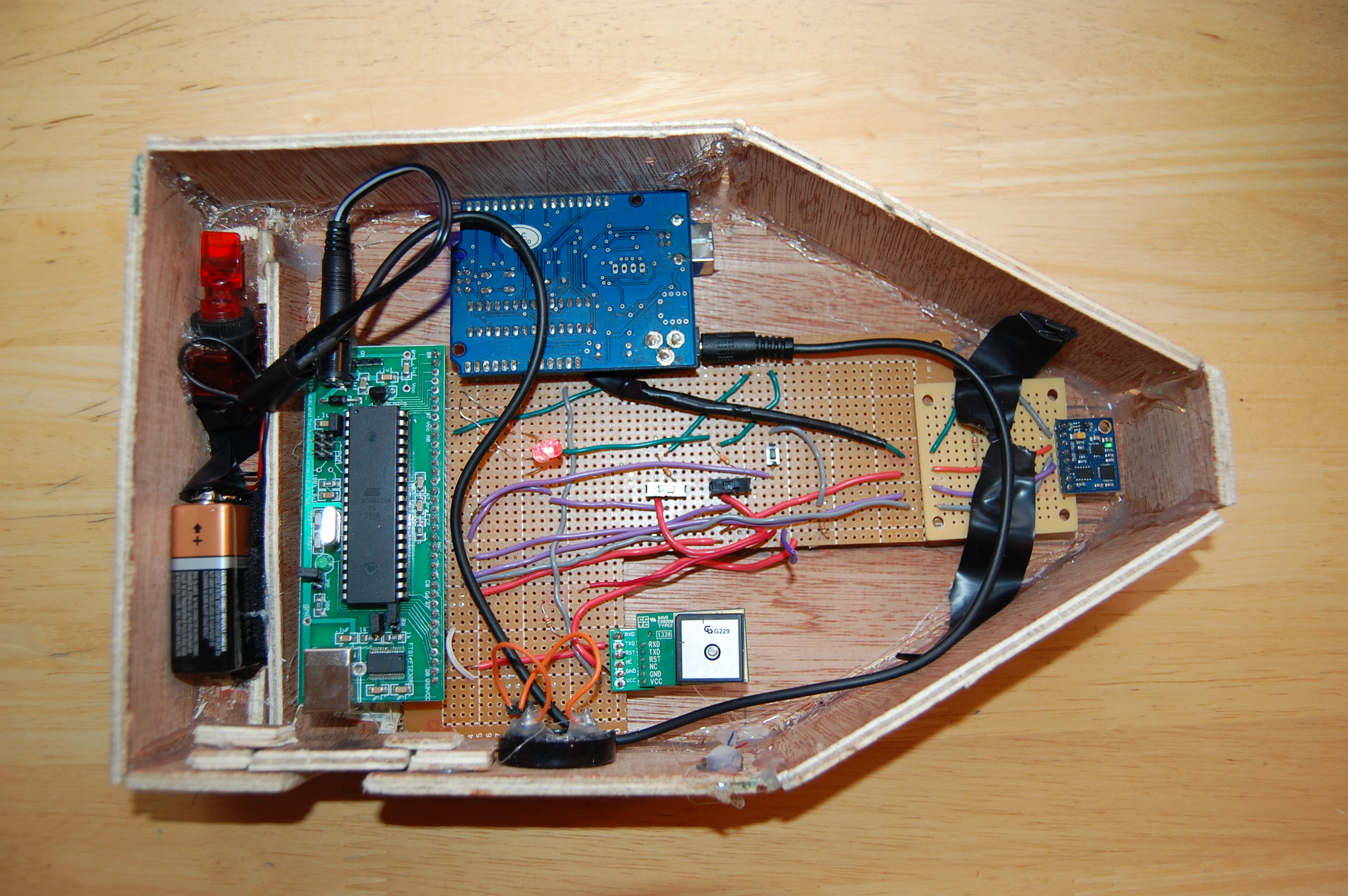
The structure of this program is as follows: data from the compass and GPS are taken into the microcontroller, and is then processed to determine where the user is in space, and which direction they are facing. Based on these data, the device then generates feedback on whether or not they are getting closer to the right place, or are even facing the right direction.
Hardware and Software Tradeoffs
The crucial parts of our project needed to be done in software, as interpreting GPS or compass data via hardware is extremely difficult, if not impossible. Hardware that was necessary included voltage conversion to power the different components, and the buttons that would allow us to switch modes. Our hardware lacked complexity due to our focus and time spent on developing software.
Hardware top
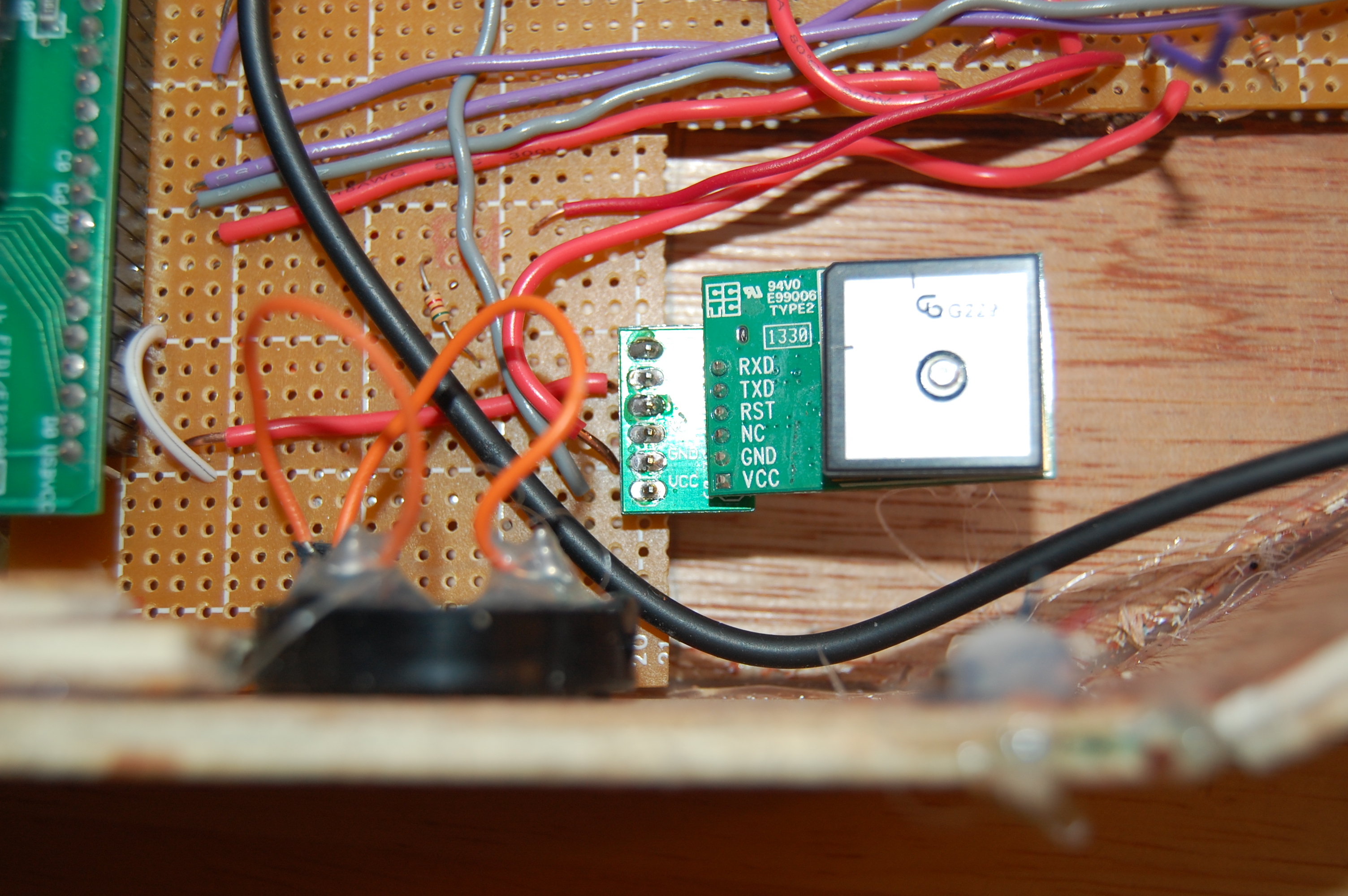
GPS Module in our prototype.
The GPS Module (Skylab SKM53)
The GPS hardware is extremely simple, it’s default configuration has it send data over Uart at 9600 BAUD as soon as it has power, so it requires no software setup. We did however modify code by Jeff Melville and Matt Kuzbeda to work at 9600 BAUD (their uart worked at 4800 BAUD). We also had to take into consideration the stability of this data, since it is sent at 2.85 Volts high from the GPS and received at 5 Volts (3 Volt minimum) High at the atmega 1284p, so it is technically below the proper logic level. This proved to not be a problem, but would definitely be something to fix with a unidirectional logic level converter from 2.85 to 5 volts in the future. The GPS is powered by the Arduino +5 Volts (connected to GPS Vcc, which is designed for 5 Volts despite the 2.85 logic level output) and the ground pin is connected to the universal ground.
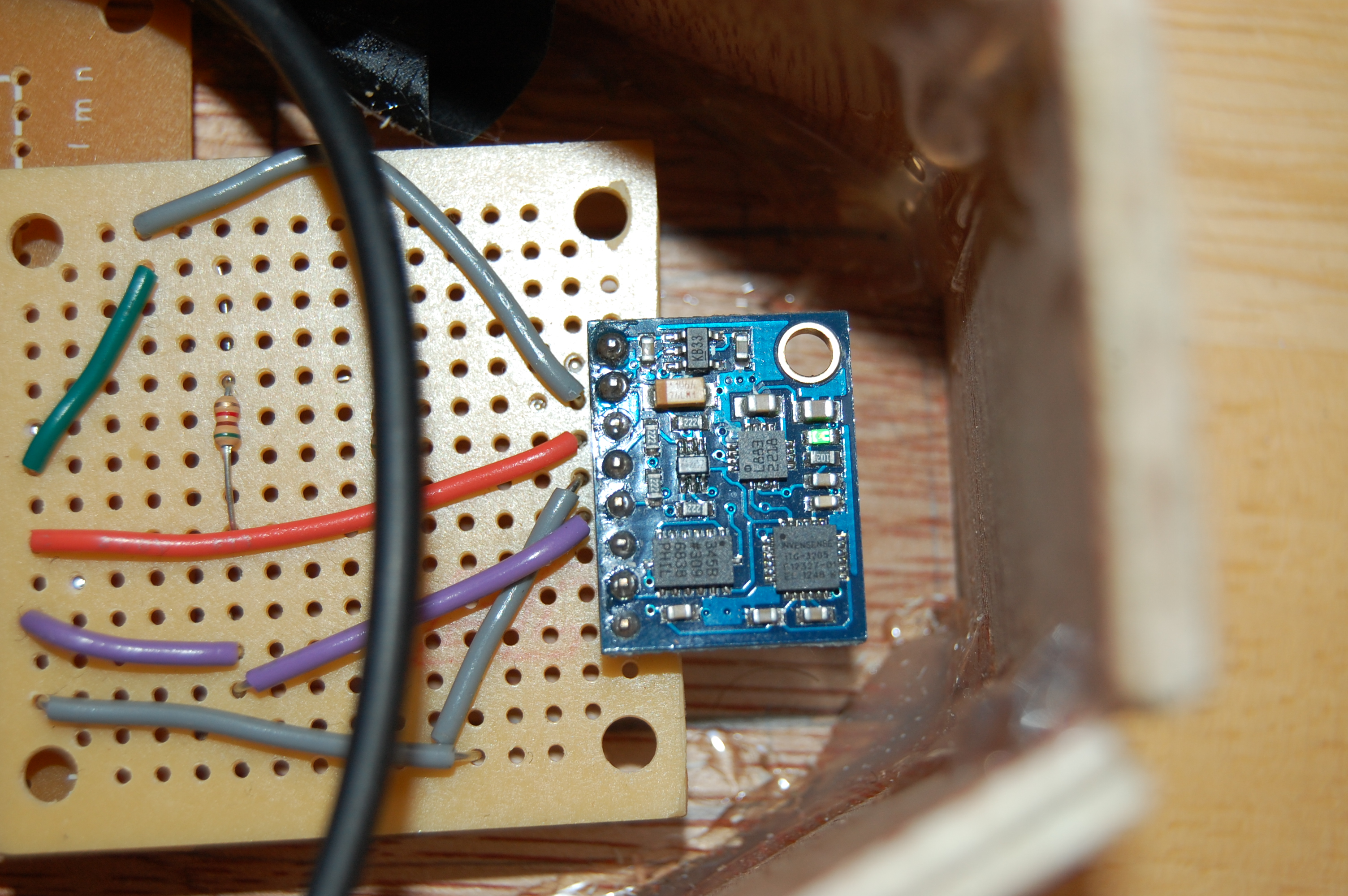
IMU Module in our prototype. The compass is found on this chip.
Compass (HMC5883L on the GY 85 intertial measurement unit)
The compass hardware was very difficult to set up. The compass is part of a larger unit, the GY 85, which also includes an accelerometer and gyroscope, both of which are unused. The compass works over I2C protocol, so the SCL and SDA pins must be connected to the designated SCL and SDA pins on the atmega 1284p. These pins on the 1284p are C0 (SCL) and C1 (SDA), but in Peter Fleury’s I2C library the assembly file has the pins set to D4 and D5. We changed these pins and then we had to also change the assembly file to include atmega 1284p as part of it’s supported MCUs. We also needed to add pullup resistors from the SDA and SCL lines to the 3.3V power source (same line as powers the compass, check the circuit diagram for clarification).
Switches and Button
The switches and the button function fairly regularly, the switches are treated as a 2 bit binary number, so when they are checked, they return a value from 0-3. (more information in the check_switches() function). When the button is pressed, it returns low, so we had to code with that in mind. The button is only updated in the switches call of the main function (or the compass calibration, but that is it’s own loop).
Software top
Program Details
The ‘meat’ of the program comes in the form of a large while loop with many nested if statements to check the various conditions governing the feedback systems. We used old GPS code from Jeff Melville and Matt Kuzdeba. We also used a modified version of Joerg Wunsch’s Uart code (modified by Jeff Melville and us). Another library used by us is Peter Fleury’s I2C library (recommended by Bruce and everybody on the internet). The tricky parts came from finding small errors or incompatabilities. For instance in the I2C library, there was no definition for the ATMEGA1284p in the assembler file, so we had to write our own. The I2C was difficult to use even after we got the library working, we had to research the protocol itself, and search for the proper registers on the compass datasheet. Aditionally, we originally thought that using fscanf() to fetch the GPS data string would work, but we were mistaken. We did end up finding the old GPS code, but we had to modify parts of it and understand how it functions. It did provide us with a great alternative to fscanf(), using the Uart interrupt it is able to collect the GPS and store it in a circular buffer, which we then interpret into a character array.
Program Listings
The Main Function
The Main() function has the initialization phase and the infinite while loop. When the program enters the main function, it begins by running the individual initializations (described in full in the initializations function of software) and initializing variables that are used exclusively in the main loop, such as the latitude and longitude list, a universal iterator, and sets the button and switches, initializing them to their correct values. The main loop then enters an infinite while loop where it runs three separate subroutines; the GPS, the compass and the switches/buttons subroutines. These are called when their respective counts are zero. When they are called, they reset their counter to it’s proper value, allowing us to set separate delays for each subroutine. The counters are decremented every millisecond in the timer0 interrupt (covered in the next section). The gps delay is 750 ms, the compass is 200 ms, and the switches are 100 ms. The subroutines each have different functionalities depending on the mode the device is in, as determined by the latest running of the switches/buttons subroutine.
Compass Subroutine
The compass subroutine does nothing for mode 0 (trailblazer mode) it simply passes the control back to the main loop after resetting it’s count. In mode 1 (hiker mode) the compass flashes red and green quickly if the universal iterator x is 0. x keeps track of where in the list of coordinates we are, so if x==0, we have completed the trail or have not initialized it yet. If x>0, then it updates the LEDs with the absolute value of the difference between the corrected compass heading (see the heading section) and the GPS calculated angle (see related section) then returns control to the main function. If the mode is 2 or 3, the compass subroutine enters the compass calibration mode, which is covered in it’s own section, since it stops normal functionality and enters it’s own loop.
GPS Subroutine
This subroutine records the reading from the last time the GPS subroutine was run in the variables llat and llon (last lat and last lon). It then runs NmeaProcessTask(), which sets lat and lon to the current reading from the GPS. If longitude == latitude, then it blinks the LED so as to let the user know that the GPS is outputting bad data. This is because when longitude == latitude, the most common case is they are both 0.00 coming from the GPS. This technically means that the GPs will not work at certain points on earth where longitude==latitude, but in Ithaca, we’re at ~42, ~ -76, so we are very safely not near one of these points. If we have latitudes and longitudes that are nonzero, then we check which mode the device is in. If the device is in mode 0, trailblazer mode, then we check to see if the current coordinates equal the last coordinates. If these coordinates are the same, it means we are receiving a stable location from the satellite, so we indicate this to the user by setting the red LED low and the green LED high. If we are setting the first point of the path, then that is all we do, but if we are not at the first point, we check to make sure the distance between the last point set and our current location is above a certain threshold (15-30 feet, but our code handles this as essentially unitless distances). If it isn’t then the LED remains red, this is so that we cannot set two points in a row that are within the “arrival” distance from one anohter. If we are far from our last point, and the reading is stable the LED turns green, and in the switches section we are allowed to record the point. If the mode is 1 during hte GPS call, hiker mode is enabled and we want to seek the path that we just set. We do this by checking x. If x is 0, then the device flashes red and green to signify that the path has been completed by the hiker or not initialized beforehand. If x is greater than 0, we calculate the euclidian distance between our coordinates and the next coordinates, and set hte blue LED to the appropriate intensity based on our distance. The intensity of the blue LED is set to arbitrary intensities at arbitrary distances. We then check to see if our distance is below our accepted “arrival,” threshold, and if it is, then we have arrived at the next point in our path. Upon arrival, we play a beeping sound, decrement x, and set the next target coordinates (nlat and nlon) to the next coordinate on the list. No matter which mode we are in, at the end of the GPS subroutine we update the calculated angle of the GPS relative to it’s next point.
Switches/Button Subroutine
In the switches/button (sw/b) subroutine, the device checks the switches and updates the mode first. Then it checks the mode, and if we are in trailblazer mode, with a stable signal (checks if the green LED is on), the distance between our current coordinates and the last point set is above a threshold and the button is pressed, iterate x and record the current waypoint in the waypoints list.We skip calculating distance if x = 0 because there is no next waypoint and the program tries to evaluate the coordinates list with a negative index (which will crash the system half hte time and return -3400000000000000000000.0000000000000 the other half). If the distance is far enough from the last point, and the green LED is on (meaning the signal is stable) and the button is pressed when this subroutine is run, it plays a sound updates the list and increments x.
Interrupts
There are two interrupts used in this program: timer 0 and timer usart RX. The timer 0 interrupt acts as a counter, decrementing the individual counters of the subroutines each time it runs. It is set to run every millisecond, so it allows for easy conversion from cycles to milliseconds, and easy scheduling. This is a very simple interrupt that we have used many times before. The usart RX interrupt runs whenever a character is received by the uart0rx (pin D.0). It simply passes the value of this character into the circular buffer used by the nmea processing functions.
Initializations
uart_init()
Initializes Uart0, beginning the collection of Uart characters to put into a circular buffer, found in the Uart.c file. This function is defined in uart.c (created by Joerg Wursch and modified by Jeff Melville and then us) This function simply sets the uart baud appropriately depending on the CPU rate, and then enables transmission and receive functions, and creates variables to keep track of the state of transmitting.
initGPS()
init_GPS() initializes latitude and longitude global variables, it can be found in nmea.c. It does nothing else ohter than initialize these variables.
i2c_init()
I2C init given in Peter Fleury’s I2C library. It sets up the I2C for transmit and receive.
comp_init()
Initializes the compass, setting it’s configuration registers (A and B at addresses 00 and 01) and it’s mode register (address 02). It sets config register A to 0x70 (set sample averaging on, this averages the last 8 readings and data output rate ot 15 Hz). This information can be found in the register descriptions found on the HMC5883L datasheet. It sets config register B to 0xA0, which sets the gain of the device to 390, with a recommended sensor field range of +/- 4.7 Gauss. Mode register is set to 00, which is continuous measurement mode.
feedback_init()
This function sets up our feedback systems, such as the button, the LED and the speaker. It sets the registers of the 1284p and sets the pin directions. For the four PWM we used, we set the following
registers:
For OC0A (red) and OC0B (green):
Timer counter control register 0 A: set COM0A1, WGM00, WGM01,COM0B1 to 1.
(This enables OC0A and OC0B PWM mode.)
Set PINB3 (OC0A) and PINB4 (OC0B) to outputs.
Set TCCR0B to 3, this enables a prescalar of 64 on OC0A and OC0B.
Enable timer/counter0 output compare match A interrupt enable.
for OC1A (speaker) and OC1B (blue):
Set PIND4 and PIND5 to outputs.
Timer Counter Control Register 1 A: set COM1A1, WGM10, WGM11,COM1B1 to 1.
(this enables OC1A and OC1B)
Set TCCR1B to 2, enables clock prescalar of 8.
The blue LED and the speaker run at a faster rate (smaller prescaler) than OC0A and OC0B, which have a prescaler of 64. The modifications to TCCR1A and TCCR0A are to enable compare match PWM mode.
calc_dist()
This function calculates the euclidian distance between our current latitude and longitude and the next latitude and longitude. This euclidian distance is essentially unitless, since latitude and longitude are not a real grid, but a a grid mapped to the face of a sphere. The distance between two longitude lines varies by latitude, so there is no simple, universal solution to this. But Ithaca is very small, so this approximation will work and be accurate anywhere within city limits, and the way we interpret the units is up to us.
calc_angle()
This function calculates the arctangent using the difference btween the current latitude and the next latitude and the difference between the current longitude and the next longitude as arguments. This gives us a value of -180 to 180, which we correct to an angle between 0 and 360 relative to southwest (just like heading() below). Just like in heading(), we use atan2 to calculate the arctangent, and then the arctangent is multiplied by 180/Pi to convert it from radians into degrees. If the angle is close to southwest, it can interpret a difference of above 180, since if our desired angle is 1 and our calculated angle is 359, the real difference is 2, but the calculated diference is 358. So we coded a corner case where we add 495 to the negative value to map it to the correct place. We add 135 to anything else that is not within 45 degrees of -180, this is to map our function to 0-360. We then ‘reverse’ the direction of the reading to be clockwise (like heading is clockwise from southwest) by taking 360- our corrected angle, and return this.
heading()
This function reads the data registers of the compass and interprets the value, then corrects the value to a mapping based on the compass’ calibration. (it is partially based on code found online, referenced in a link below, and also in a comment at the top of the beaconcode.c file) It begins by initializing three values for the x, y and z (z is unused but must be read to get to the y value) values to be stored in. It then lets the compass know that it wants to receive the data in it’s data registers using i2c_start_wait, with the argument of the compass’ address with a 1 at the end. Then it repeatedly reads from the compass starting at the x value, and reading the z then y. Each register has 16 bits of information, and the two registers form a single 16 bit integer when OR’d together. Once we have all of the register values, we can compute the heading using the function atan2 (arctangent function). We pass the y and x readings to atan2, and then multiply by a scalar (57 = 180/pi). We then add 180 because atan2 outputs a value between -180 to 180, so the value is corrected to 0 to 360. This value is relative to southwest (0 and 360 are southwest, 180 is northeast ideally). We found that the value was inaccurate, it completes 360 degrees in a full turn, but the difference between southwest and west (expected to be 45) could be anywhere from 30-70, so we had to map these directions more accurately. We divided the circle into eight segments (45 degrees each) and starting from southwest, we initialized default values for what the reading is expected to be (for instance west could be 30). If this is the case then we scale west by 45/(west-southwest) which gives us 45/30. So our reading between west and southwest is (reading)*(45/30). For the area between west and northwest, we add 45 degrees and scale it similarly. corrected_reading=(reading*(45/(northwest-southwest)))+45 so our readings will always be accurate at the eight headings, and accurate within 45 degrees (but more realistically ~5 degrees maximum error) in between the eight essential headings. This function returns the corrected angle, but sets the global variable “H” to the raw compass reading, which is used for the compass calibration function. The default readings for the eight directions are set at the corner of Stewart Ave and State st. The corrected output is what is used when determining the angle between the GPS coordinate angle and the heading, described in the Main section.
Compass Calibration Mode (essentially a function)
The compass calibration mode begins whenever the compass subroutine is called and the mode is 2 or 3. While hte mode is 2 or 3, the compass calibration mode stops the rest of the program and begins a while loop. In this while loop it allows the user to change the calibration directions of the compass. That is, if the north raw compass reading is set to 78 as default (it isn’t) and we’re reading that the actual direction is a raw reading of 90, we can change this in the compass calibration mode. It acts similarly to the hiker mode, but instead uses the LED to let the user know when they are pointing specific directions according to the compass and set them to new directions. It starts with south, using the raw reading “H’ variable form heading(), it compares that to the current assumed heading for south, and updates hte LED so that it’s more green the closer to pointing towards the south you are. Using a real compass, you can point the device to real south, and press the button, which will set the “SOU” variable to the new compass raw reading. This means that when the heading is calculated, it’s now corrected with this new value for south in mind. Then it sweeps counter clockwise, having the user set southwest, west, and so on until they set southeast, at which point it’s completed. Each time a point is set, threebeeps() is run, and the processor is blocked until the beeps stop, this is to let the user know that they should take their finger off the button before the beeps end. The user can leave this function at any time while it’s running, if they reenter the function it will begin again at south, but if they leave early, it will save their current changes and the rest will remain at whatever value they entered calibration mode at.
Feedback Functions
update_LEDs(degrees int)
This function expects an int from value 0-180, and updates the red and green PWM values accordingly. The value passed to it is the difference between the GPS calculated angle relative to southwest counterclockwise (west is 45 degrees, northwest is 90 degrees...south is 345 degrees) and the compass reading corrected by heading(). If the value is below 30, that is the difference between the desired direction and the compass heading is below 30 degrees, then the green pwm is set such that the closer to 0 it is, the higher the intensity. When above 15, the red LED pwm is lowered the closer the difference is to 0. This is to simulate how close the compass heading is to the actual angle determined between the current location and the next location on the hiker mode. If the value is above 30, the red LED is set to fully on and the green to fully off. The value of the LEDs is set with a simple linear correlation to the angle passed. The green LED updates as (angle)*(255/30), such that when the angle is zero, the GPWM is at full intensity (GPWM=0). The red PWM is set to 255- (angle)*(255/180), and is completely off when the the angle is below 15. This function is also used as a way to update the LEDs to set values, for instance if we want to set the red light on and the green off, then we simply pass it a value of 180. This sort of functionality is used as the trailblazer stabilization indicator.
check_button()
The check button runs a simple and statement between binary PINC and one bitshifted by 7, so as to read the pin C.7 value. It returns 1 if the button is not pressed and 0 if the button is pressed.
threebeeps()
This function is a BLOCKING function that plays three beeps. It employs the play_sound() function to play the beeps, and uses soundcnt with a while loop to add a delay between the three beeps. This function was designed to be blocking on purpose, and is used mainly in the compass calibration mode as a way to block user input while iterating between directions. (see compass calibration mode for mode information).
vibrate_motor()
Unused function designed to turn the motor on and off. This could be used in future revisions, but is unused in the demonstration and the final code.
play_sound(Sound Length int, Sound PWM value int)
This function plays a sound for the desired length and at the desired PWM (the speaker is on OC1B), we only use this to generate a square wave at a single frequency, half duty cycle (PWM=512 out of a possible 1023). This function is NON BLOCKING unlike threebeeps(). This is accomplished by setting the PWM and the sound counter when the function is called, and then decrementing soundcount in the scheduling interrupt service routine on timer 0. When soundcount is 0, the interrupt will set OCR1B to off, so the speaker is silent.
check_switches()
Check switches returns a binary sum of the two switches. If the switches are 0 and 1, then it returns 1, if the switches are 1 and 0, it returns 2 and so on. This results in a value between 0 and 3, which determines which mode the device should be in. If it’s mode 0, it’s in trailblazer mode, if the mode is 1 it’s in hiker mode, and modes 2 and 3 are identical compass calibration modes.
Description of Other's Code
nmea.c (Jeff Melville and Matt Kuzdeba)
This file contains the functionality used to interpret the message sent by the GPS over uart. We only use gpsinit() and Nmeaprocesstask() functions. gpsinit() simply creates a few variables we need such as lat and lon. Nmeaprocesstask() takes the data in the uart receive circular buffer, and processes it depending on what the message type is. NMEA protocol has several possible messages, only one of which was important to us (latitude and longitude). It can also receive time and number of satellites. While we did use the number of satellites for debugging, we decided not to process it in our final project because the user doesn’t need to know this value. When the type of message with location information (GGA) is detected, it parses it into lat and lon, and assigns them their respective values, which can then be used in our code. This code was fairly easy to integrate into our code, we removed some functionality (interpreting types of sentences other than GGA), other than that it’s mostly untouched.
uart.c (Joerg Wunsch, modified by Jeff Melville and Matt Kuzdeba)
We only changed the BAUD rate here, and learned how to integrate it into our code. We needed to enable the USART interrupt, which triggers when there is a character available. This enables us to collect GPS messages as they happen without blocking, as opposed to collecting GPS messages with fscanf which blocks.
i2cmaster.S (Peter Fleury)
The i2cmaster.S is included as a sourcefile alongside our beaconcode.c file in the project. It took us some time to figure this out, we originally thought that simply adding an include and having it in the same folder as our project would work, but it didn’t. So we eventually figured out that it needed to be included as a source file. Once we had it compiling, we were not receiving any data over the line. We found that the assembly file pointed the SDA and SCL pins to D4 and D5, which we then changed to C0 (SCL) and C1(SDA). Once this was added and the physical data line was properly constructed, we were able to send and receive data from the compass over I2C.
Attempts that were not initially functional
Everything. Every step was trial and error, and a lot of walking around outside mumbling to yourself about how the light isn’t the right color. Debugging this project was incredibly difficult, as things like “correct angle,” could only be debugged outside (and not in a car because it’s magnetic field interferes with the compass!) Our first issues arose with the I2C communications, we were having difficulty accessing and storing the correct data. After researching the compass data sheet, we discovered we were accessing the wrong registers for the compass, or setting the wrong bits in a register, or calling the wrong address for the device.
Results top
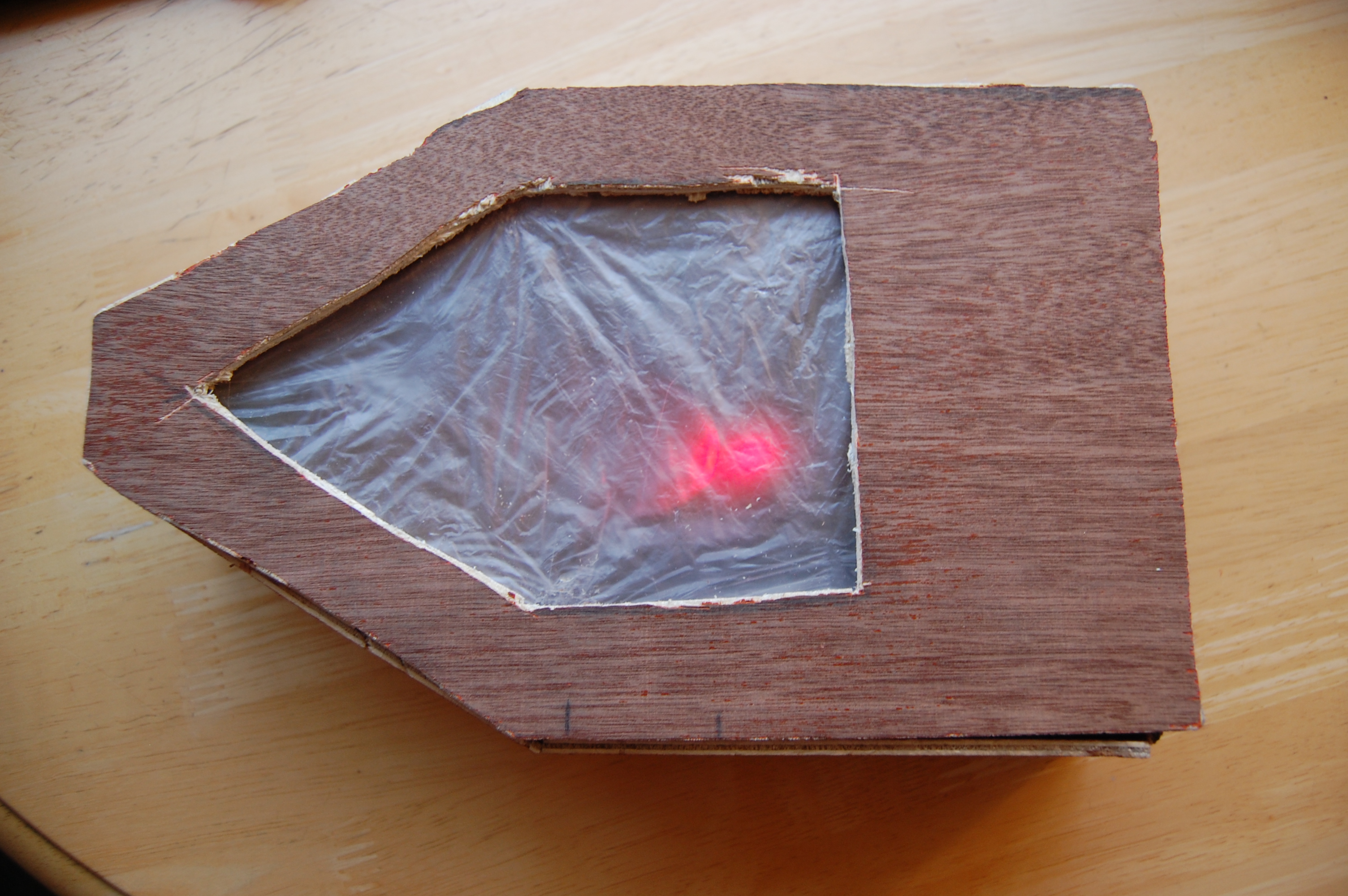
Our original intention was to design a device that explained itself, and our implementation was relatively successful in this venture. We have two versions of code, our stable version which never crashes and our experimental version, which has more features but is known to crash from time to time. Really the true measure of our success is the fluidity of interaction with the user and the accuracy of the LED’s visual feedback to guide the users to the next point. Standing about 70 feet from the next point, it’s not uncommon to look at the LED feedback and feel like you’re off by a few degrees. When setting points very far away (500+ feet) the compass feels like it is dead on. Because of this, we set an area around each point, once the user gets within a certain distance of the point (usually 10-15 feet) it will trigger an arrival. Because of this area around the point, the Beac0n will bring users to the point pretty reliably, so long as the compass is calibrated correctly. The compass caused other issues as well - it is just a magnetometer that senses the earth’s magnetic field. Because of this, it was very susceptible to interfering magnetic fields. This was problematic when testing the device on the engineering quad - as the compass did not point in the proper direction once close enough to a manhole cover. This type of error was replicated on a smartphone compass, where for some reason, the compass thought west was north. It is a reasonable assumption that both compasses function using magnetometry, so seeing that error on another device meant the problem was found in our hardware and not our software. During testing and demoing, moving away from the interfering magnetic field seemed to help quite a bit, as we were able to accurately move to a set waypoint. The LED was very responsive during the demo, with the blue light clearly indicating distance, and the red and green gradient indicating correct direction. We did not particularly enforce safety with this design because all of the components were low power and not very dangerous. One possibly dangerous case of this project would be a particularly inattentive user. If they are too focused on the feedback of the device and are not watching where they are going, there is a chance that they will trip and potentially hurt themselves. One potential improvement to this device could be some sort of ultrasonic sensor that will indicate to the user they should stop moving forward. Our device did not interfere with other groups’ devices, as it is a passive device that only receives data. The only interference our device could provide would be a person using it physically getting in someone elses’ way. The device was very usable, and could very likely be used by anyone that wanted to use it! Future design changes would include making the device even more user friendly, with a more compact design, and a larger set of LEDs to indicate proper direction.
The device pointing in the wrong direction.
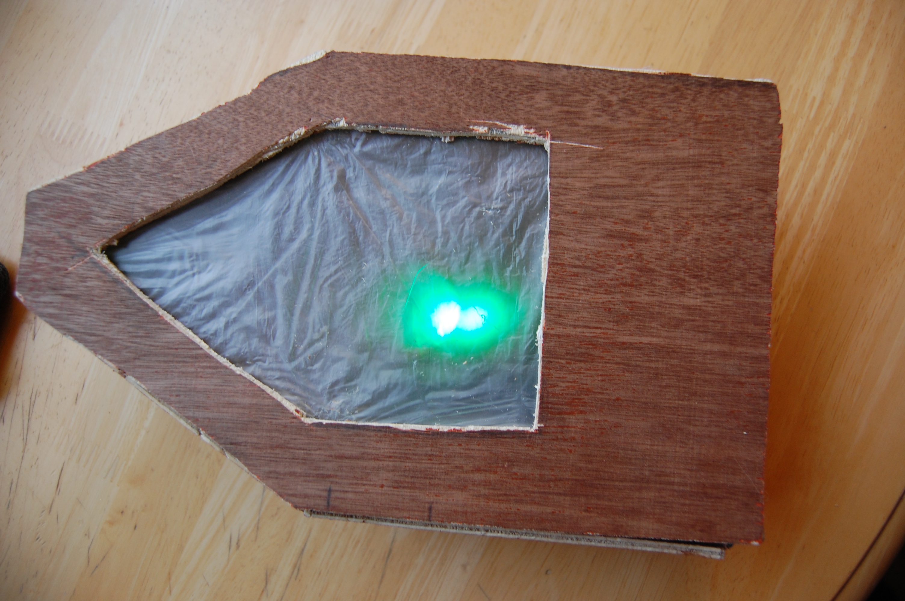
The device pointing in the right direction!
Conclusions top
The results did match our expectations to some degree. We were able to build a GPS pathfinder that operated rather well, except in the presence of exterior magnetic fields. Unfortunately, due to time constraints, we were unable to test the device from a ‘zero-instruction’ perspective, though it does seem that the device would be rather intuitive. While this project was a success in that it could navigate from place to place, we did not truly get to test its ‘zero-instruction-device’ functionality. Had we had more time, we would have liked to leave it with people, and see if they could use it to find their way based on the feedback provided by the device. Because we were unsure of how many feedback features we could implement, we purchased a three-device integrated circuit (a compass, a gyroscope, and an accelerometer), that all could have been used in concert with one another to improve the accuracy of the device. We also experimented with the ability to calibrate the compass on the fly, instead of having to upload new numbers representing certain cardinal directions every time we recognized that it was off. One way to do this would be to have a calibration mode that could be switched to before the trailblazer started walking the path. To calibrate it, you could use an independent compass, and then when the device is pointing north, press the button to indicate which direction you are facing. Another future improvement would be to make this device work indoors. This is a very challenging task, as GPS gets removed from the equation once there is a roof over your head. One idea that we toyed with was to use the accelerometer for indoor use. Using the acceleration, some mathematical operations could give us the device’s change in position, which then would allow us to know which direction they should be going. (This is very challenging, but definitely something to think about.) To provide even more feedback to the user, you could include a vibration motor that would buzz when the hiker goes the wrong way. This would make sure that even if they were not looking at the device, they had some manner of understanding which direction would be correct. (It could even be configured such that the motor vibrates when they’re off the path, sort of like an invisible wall that keeps them on the right track.) This was planned for this revision of the device, but for some reason it stopped working right before demo day. To improve a device with just this base level of functionality, you can purchase just a compass instead of an IMU, which would decrease the cost and size. Another improvement would be to make the physical body more appealing. We were originally envisioning a device that would have a solid white bottom, and an opaque top. The opaque top would change colors with the LED, and it would look much more natural.
Applicable Standards
The design of our device used UART, and I2C standards, and worked quite well with them. Our UART and I2C communications were implemented at correct baud rates, and the messages sent and received were also proper according to their respective standards.
Intellectual Property Considerations
The code reused in our design primarily consists of Peter Fleury’s I2C library, Jeff Melville and Matt Kuzdeba’s UART code. Peter Fleury’s I2C library has become the standard for I2C communication, and came highly recommended by Dr. Land. This code is in the public domain, and is used by many. The UART code from Jeff Melville and Matt Kuzdeba was written for ECE 4760 a few years back. Because of this, Dr. Land allowed us to use it in our project. We did not have to sign any non-disclosure agreements, as we simply purchased consumer-grade products. It does not seem that we should patent this device, as it is a combination of a compass and a GPS module, which has more than likely already been patented. We could publish this project if we ran an experiment on the zero instruction device aspect of it. This would either prove or disprove whether or not people can have instincts regarding technology, which would actually be quite interesting. To build our website, we adapted a Cornell template used by Cameron Glass, Roland Krieger, and Omeo Quddus, the ECE 4760 hand-motion chess team in fall of 2012.
Ethical Considerations
Our project, and the creation thereof was absolutely consistent with the IEEE Code of Ethics. We were constantly conscious of our surroundings, and the use of safety protocols with tools. For instance, whenever a soldering iron was used, we made sure to wear goggles. After thinking it through, we came to the conclusion that there are not any conflicts of interests, as this tech was a combination of pre-existing technology. We were not bribed in any way with regards to this project, and absolutely assisted our colleagues whenever possible. Our device treats all people fairly, and hopes to have uniform understanding across all first-world cultures. (People in less technologically-advanced areas would not necessarily understand technological feedback, which is what this project focuses on.) Number 7 in the code of ethics was very familiar to us, as we continuously got feedback from each other about our work to ensure that it was the best it could possibly be. We corrected as many errors as we possibly could on the project based on the discussions we have had. We also did an excellent job not injuring anyone as listed in number 9 of the IEEE code of ethics. A total of 0 people were harmed in the making of this project!
Legal Considerations
This device does not break any laws. If it stored GPS data and sent it to other places, however, that may cause some privacy issues. Luckily, there’s no real reason to store user’s data on this device. There are laws against tracking others with GPS devices, but the beac0n does not have any transmitters on it, just receivers.
Appendices top
A. Schematic
Hardware Schematic
B. Budget
| Part | Vendor | Cost/Unit | Quantity | Total Cost |
|---|---|---|---|---|
| Atmega 1284 | Lab Stock | $5 | 1 | $5 |
| SKM53 (GPS Module) | ebay (user: nooelec) | $22.75 | 1 | $22.75 |
| GY 85 IMU (Included Compass) | ebay (user: alice1101983) | $10.98 | 1 | $10.98 |
| Arduino Due (Power Supply) | ebay (user: power59296) | $10.99 | 1 | $10.99 |
| Perf Boards | ebay (user: jpmultiserve) | $6.56 | 1 | $6.56 | Plexiglass | Home Depot | $4.38 | 1 | $4.38 | ECE 4760 ATMega Board | Lab Stock | $5 | 1 | $5 |
| push buttons | Lab Stock | $0 | 1 | $0 |
| Switches | Lab Stock | $0 | 2 | $0 |
| Piezoelectric Speaker | Lab Stock | $2 | 1 | $2 |
| 9V Battery | Dollar Store | $2 | 1 | $2 |
| Wood | Found in Trash | $0 | 1 | $0 |
| Wires and Resistors | Lab Stock | $0 | many | $0 |
| TOTAL: | $64.16 |
C. Source Code
D. Division of Labor
Dustin Franco
- Final Code Structure
- I2C Compass Integration
- UART GPS Integration
- Hardware Construction
William Milne
- GPS Formulas and Calculation Methods
- LED Feedback System Code
- Mode Select Switch Wiring
- Voltage Dividers and Motor Controller Circuits (Neither was used in the final version.)
Both
- High Level Code Design
- Sounding Function
Acknowledgements top
We would like to thank Bruce Land for putting this course together, and making it so interesting throughout the semester. We would also like to thank Roland, our lab TA for all of the help he provided whenever we would hit a brick wall in our code or in our hardware. This course has been an amazing experience, and the things we've learned from it will be incredibly valuable in the future. Thanks!