High-Level Design
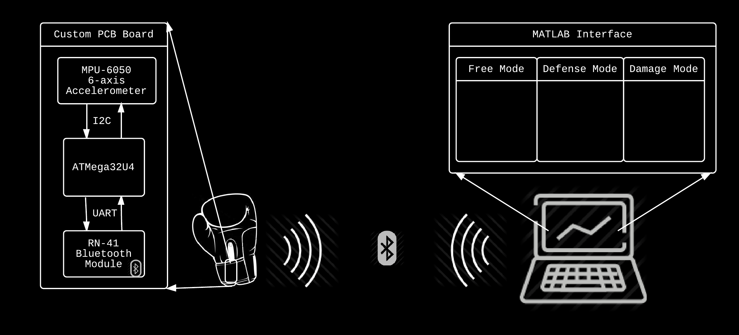
Fight Coach hardware is organized into 4 main subsystems:
• Power management - responsible for providing the Fight Coach with lightweight, recheargeable power.
• MCU - The ATMEGA32U4 microcontroller
• Bluetooth Module - The RN-41 Bluetooth wirelress transceiver
• Accelerometer and Gyroscope - The MPU-6050 IC by Invensense
• Motion data, generated by the MPU-6050, is obtained by the MCU via i2c, and the MCU then transmits that data to a
Bluetooth module via UART, which in turn gets displayed and processed on a matlab terminal.
User Interface
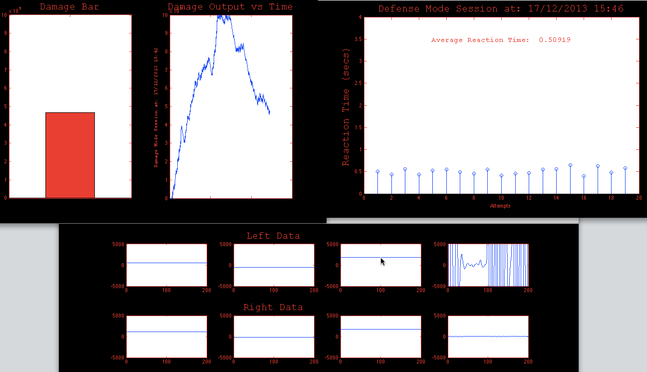
Figure 1 as shown below shows our user interface
Our User Interface had to accomplish the following functional requirements
• The user interface shall display athletic performance statistics in real-time
• The user interface shall gauge the athlete's defensive abilities by sending audio commands that would simulate strikes
from an opponent.
• The user interface shall display the athlete's defensive performance in real-time.
• The user interface shall gauge and display the athlete's damage output.
• The user interface shall play the Street Fighter Theme once the intensity of their practice session has surpassed a level of
the user's choosing.
• The user interface should display the date and time of each practice session
• The user interface shall allow the athlete to switch between the different practice modes, and audibly indicate which mode
the user has selected.
• The user interface should store the data generated by the session so that the athlete can log and track his performance
over time
We decided that the most efficient way to implement the aformenetioned requirements is to use Matlab. The alternative was
to test our questionnable objective-C abilities and write an iPhone app that would accomplish the user inferface requirements,
but we decided that it wouldn't be worth the risk.
Matlab provided us with a variety of key benefits. The serial object allowed us to easily create a program that would interface
with the computer serial port (which was receiving data from the bluetooth module on the Fight Coach) with the 'fopen()' and
'fscanf()' commands. Also the 'audioplayer' object made it easy to implement the audio requirements of our system.
Implementation details of the user interface can be found in the Software section.
Tradeoffs
MPU-6050 and sensor tradeoffs
We chose the MPU-6050 because it integrates an accelerometer and gyroscope into small, power efficient package. When
considering the wide range of available accelerometers, we initially considered the MPU-6000 for its SPI capabilities. However
logistics (quantities available on digi-key, and shipping times) prevented us from using the MPU-6000 and so we opted for the
MPU-6050 We also chose the MPU-60XX family because of its Digital-Motion-Processor, which allows us to offload some of
the MCU computation onto the MPU-6050 so that more complex motion processing algorithms could be implemented. In
particular, the Digital-Motion-Processor would allow us to implement a Mahony filter, that would allow us to more accurately
obtain the attitude of the sensor (more details on our implementation attempt and failure is disccussed in the Sofrware
section).
Size vs range (bluetooth module)
Our bluetooth transmitter is the largest component on our board. Also, it is the most expensive. We looked at other smaller
and cheaper class II bluetooth modules (in particular, the RN-42 by Roving Networks, and the PAN1325 by Panasonic), but we
realized that their range was around 10m (which is slightly smaller than the size of an MMA Octagon). Furthermore, we
wanted the OSF to work in a large room with a fixed MatLab terminal, and so we favored the long-range RN-41.
What was also helpful was that the documentation for both the RN-41 and RN-42 was thorough and comprehensive (the
development kits were also on the more affordable side). Furthermore, setting parameters such as the baud rate and error
control could be done without reprogramming the module's firmare.
Battery size and weight vs battery life
We chose the LiPo 3.7V 110mAh because we believed that it was the optimal size and weight for a 2-3 hour training session
with the atmega32u4 drawing approximately 10mA (p 379 in manual) and the RN-41 drawing 30mA (p 2 of RN-41 Manual) .
At 2.65g, the battery still carries a weight less than a percent of the weight of even the lighter-style sparring gloves (12oz
sparring gloves). The dimensions of the battery (5.7x12x28mm) also make it well suited, and small enough to fit inside most
adult sized boxing gloves or muay-thai shin guards. (https://www.sparkfun.com/products/731).
Choosing ATMEGA32U4 vs the rest: Bootloading with ISP vs Bootloading with USB
One of the main reasons that we chose the ATMEGA32U4 was because it could be programmed via USB (all atmega32u4's
are preprogrammed with a USB bootloader according to the first page of the datasheet ). This means that, if the device were
to be enclosed or embeded within a boxing glove or other encasing, that developpers and athletes could still reprogram the
hardware as needed via USB, without the need to access ISP pins (PB1 PB2 PB3 and PB13) i.e the spi pins MISO, MOSI,
SCLK,RST and GND. In other words, it is possible to design a board around the ATMEGA32U4 with no ISP headers and just a
USB, which is really helpful for minimizing size and weight of the device. However, due to reported difficulties with working with
the DFU bootloader (the bootloader that allows programming via usb). As a result, although we originally designed our board
to only include a micro-usb connector, we also included ISP-headers, to account for the possibility that we would never be
able to properly configure the DFU bootloader.
Including the ISP-headers turned out to be crucial: we were set back a week trying to get the DFU bootloader to work to no
avail (we still don't know why). Thus, as the project demo deadlines approache, we fell-back on our backup plan and
bootloaded our MCU's via ISP (with avrdude and the avrispmkII).
Link describing the difficulties in handling the DFU bootloader: http://blog.komar.be/using-atmels-dfu-bootloader-abi-on-
Relevant Standards
I2C (aka TWI)
I2C is a simple two wire interface that allows microcontrollers to interact with multiple peripherals. The accelerometer (MPU-
6050) communicates with the microcontroller using this interface.
UART (Universal Asynchronous Receiver/Transmitter )
UART is hardware that translates data between serial and parallel forms, and was used to enable communication between the
microcontroller and the bluetooth module (RN-41).
Bluetooth
Bluetooth is a wireless technology standard for exchanging data over short distances from mobile devices. We used bluetooth
to send motion data from the microcontroller to a MatLab equipped device that can receive and display fighter statistics in real
time. Note: since we are using a class 1 Bluetooth transmitter, the effective range of OSF is 100 meters (approx. 330 feet).
FCC Compliance and RoHS Compliance
Wireless capabilities of the Fight Coach are provided by RN-41 modules, which meet FCC standards (FCC CFR47 Part 15 C,
para 15.247, FCC ID: T9J-R41-1), and are class 1 output transceivers with a range of 100m at 2.4GHz ISM band. Since the
bluetooth stack responsible for power output and range cannot be accessed by the user, Fight Coach cannot violate FCC
interference, maximum power and frequency hopping specifications that ensure that electronic devies nearby aren't disrupted,
and that human radiation absorption isn't an issue. All of the parts that we have selected (shown in the Bill of Materials) are
RoHS compliant to ensure that only safe materials are used in the production of Fight Coach.
Hardware Design
Figure 2a/b below shows our hardware schematics (Click for higher resolution)
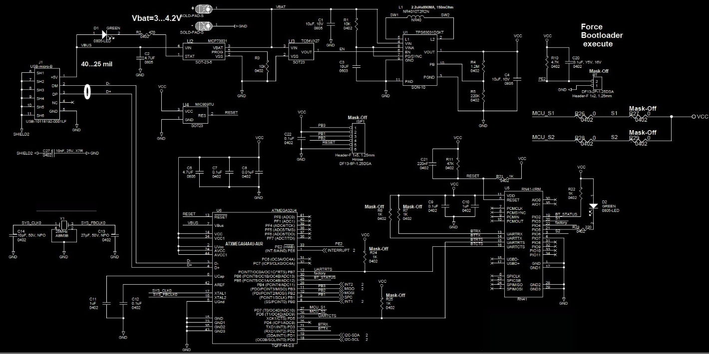

Microcontroller
As discussed in the tradeoffs section, one of the main reasons that we chose the ATMEGA32U4 was because it could be
programmed via USB, making it easy for developers to reconfigure the Fight Coach sensors to their desires. The
ATMEGA32U4 has a plethora of other features, and the following list describes only but a few of the most pertinent functions
that we found useful for the Fight Coach (in no particular order)
• 32K Bytes of In -System Programmable (ISP) Flash
• 2 16 bit Timers with separate Prescaler,compare and capture mode
• programmable USART with hardware flow control
• USB 2.0 Device Module
• 26 Programmable I/O lines
• small, 1cmx1cm TQFP package
• 8MHz at the 3.3V range
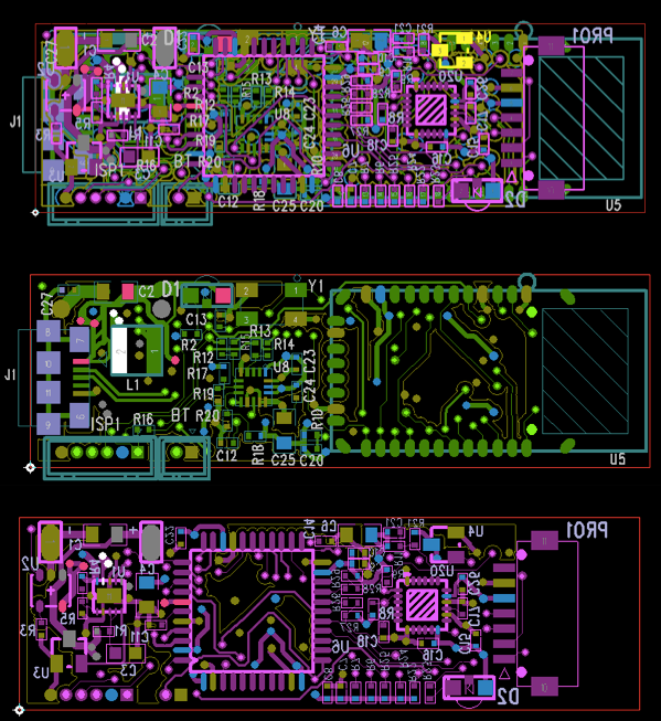
Custom board design and production
Figure 12 below shows the layout of the PCB boards for Fight Coach.
When we began this project, we knew that the Fight Coach would be subject to the conditions found in typical fight scenarios
(sweat, spit and possible even blood), which is not exactly ideal conditions for electronics. After considering the high-
impact/humidity environment that the Fight Coach would be subject to, we realized that we needed to design it small, light
and durable. To meet this goal, we needed to create a custom board that would include all of the necessary components in
the smallest package, and then encapsulate it in epoxy to create a water-resistant, protected package. We then designed our
PCBs and ordered them from quickTurnPCB (http://quickturnpcb.co.kr/quality.php) approximately 1 month before final
project season began (the lead time for ordering PCBs varies anywhere between 3 to 5 weeks, though there are some
manufacturers that can do it faster (http://tinyurl.com/72nmt6p).
Our first PCB design minimized the number of QFN packages used, and used 0603 packages for the resistors and capacitors
(they are easier to use for hot-plate reflowing since they are bigger). This is because 0402 and QFN packages are extremely
difficult to sodder by hand, though soldering tutorials using hot-plates can be found here
Fortunately for us, we were able to work out an agreement with my old employer, Mara Technologies
(http://www.maratech.ca/) so that they could could use their soldering machines to populate our boards for us. This meant
that our latest PCB design (as shown above) could use the smallest available packages for resistors and capacitors (0402) as
well as QFN packages for our final board design. Thanks Frank!
USB-LiPo Charger and Power Management
We learned early on that using a rechargeable battery, such as the LiPo on Fight Coach, meant that we needed to incorporate
circuits that would provide undervoltage protection and charge management for the LiPo and reverse discharge protection.
MCP73831: Charge Management
The first major power management component is the MCP73831: a linear charge management controller that employs a
programmable constant-current/constant-voltage algorithm. This was needed to make sure that charging the LiPo battery via
the USB would not damage or break the battery. By setting the programming resistor (at pin 5 of the MCP73831), we were
able to set the charging current to 100mA (the datasheet for the LiPo batteries show that with a charge current of 100mA,
charge times are approximately 3 Hours). Another nice aspect of the MCP73831 is the fact that it has an indicator pin that is
pulled HIGH when it is done charging. This was used in conjunction with a yellow LED light to indicate when Fight Coach was
charging, and when it was finished charging.
TPS63031: Buck-Boost Converter
Since our LiPo batteries produced variable voltages between 2.7V and 3.7V, we needed a component to convert that voltage
into a constant 3.3V (all of the most important components operated at around this voltage) . Since we wanted this voltage
conversion to occur as efficiently as possible, this drove our decision to employ the TPS63031, a buck-boost converter by
Texas Instruments. The buck-booster takes the variable battery voltage(3.1-4.2V) and converts it to the 3.3V (with up to
96% efficiency according to the datasheet) with needed by the MCU, accelerometer+gyroscope and the bluetooth module.
We weren't sure about the behavior of the power save mode for the TPS63031, and so kept it HIGH, but in future revisions,
this pin should be set LOW so that the device can oeprate more efficiently
TC54: Lock-Out Protection
The TC54 served two purposes: to protect against corrupted memory, and to protect the LiPo battery from reaching its
undervoltage.
The LiPo battery is one that cannot be used if its output voltage is below its undervoltage (which causes it to break). This
means that devices using a LiPo battery must have a component which disables the battery before it goes below its
undervoltage, so that the battery doesn't break. The TC54 acts as a voltage detector, and goes LOW once it detects the
battery voltage going below 2.7V. This disables the buck-boost converter, effectively preventing any current from coming
from the battery, thus, protecting the battery from operating in its undervoltage.
Another consequence of using the LiPo battery (and batteries in general), is that all of the components were subject to a
powersource that could be enabled or disabled with time. Furthermore, sometimes the powersource will turn on and turn off
within a very short period of time which can potentially corrupt the memory of the MCU. The TC54 protects the MCU by
introducing a delay time between when the battery voltage has surpassed the undervoltage threshold (2.7V) and when the
buck-boost converter is enabled again. In other words, the TC54 ensures that the MCU (and all devices connected to VCC)
only receives power once the battery voltage is reliably above 2.7V for at least 0.2msecs, and minimizing the chance that
MCU memory is corrupted by an unstable power source.
MPU-6050: Accelerometer and gyroscope
The MPU-6050 is main sensor for the Fight Coach. It includes an accelerometer and a gyroscope in a small package, and
interfaces with the MCU via I2C. A lot of the MPU-6050 is programmable via I2C, and so hardware configuration with this
component was minimal (we just followed the deafault typical operating circuits that were described in the datasheet p22 of
version 3.4).
Bluetooth: The RN-41
The RN-41 is the bluetooth transmitter for the Fight Coach. The module is a relatively low power transmitter (30mA during
connection, <10mA while sniffing) with a range of up to 100 meters. The RN-41 comes with TX, RX, CTS, and RTS pins that
allows it to communicate with the MCU via USART. Although we connected the RN-41 so that USART communication is
possible, we did not implement it in our code (since we were not familiar with USART flow control protocols).
Using Command Mode to set the Baud Rate
Hardware testing/debugging
One of the most time consuming bugs that we encountered while developping Fight Coach was debugging the I2C
communication. We noticed that we were not able to communicate with the MPU-6050 and obtain its accelerometer and
gyroscope data, even though we thought that we had correctly configured the circuit and used the right code (I2C routines
courtsey of Peter Fleury).
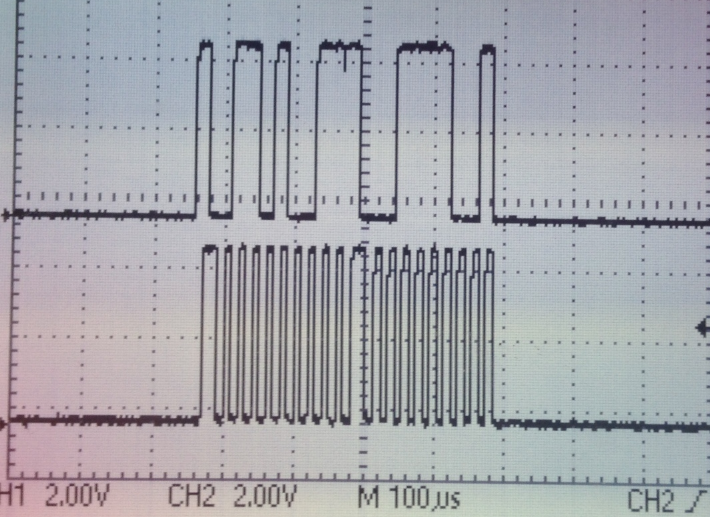
Our first debugging step was to verify that we were using the right address, so we used an oscilloscope to take a look at the
signal on the SDA and SCL lines as shown in the figure below.
Figure3 below shows us probing the SDA(top signal) and SCL(bottom signal) to verify proper I2C connectivity. We
are sending an i2c_start() signal for the address 0x68 to see if we get an ACK.
We had originally suspected that the MPU-6050 was burnt out because we had connected it wrong. What also led us to
believe that the MPU-6050 was that we had also used the MPU-9150 development kit, which is supposed to have the same
setup as the MPU-6050 (we got the MPU-9150 working just fine, and so we wondered why the MPU-6050 wasn't working
and concluded that it was broken).
Probing the I2C lines turned out to be crucial: the scope showed us that the MPU-6050 wasn't broken (as we had originally
suspected). In fact, it was giving us an ACK. This was also verified by writing an I2C sniffer (a script that just sends out
i2c_start(address) and sees which addresses return an ACK).
At this point we were able to verify that the reason we weren't able to get data from the MPU-6050 wasn't a hardware
failure, but a software failure. Still, it was important to verify that all of the hardware was in place before moving on to fix I2C
in software (as discussed in the software section)
This debugging process could have been shortened if we had extra MPU-6050's on hand so that we didn't prematurely
conclude that we had broken our only sensor(which would have led to a more thorough search through our software instead
of spending time debugging hardware). So word of advice: always order extra parts (3 or even 4 more in addition to the ones
that you need for development ) if you are on a tight time budget and don't mind spending extra coin so that you don't lose
your precious time during final project season.
Resetting a LiPo battery
As you attempt to connect your LiPo batteries to our projects, you will most likely short them at some point. During Fight
Coach, we shorted our batteries at least 2 times (because I was wearing my class ring) and we needed to reset them to that
they could work again. Instructions on how to reset a LiPo battery were found here
(http://www.tictoctrac.com/soldering.php#lipo) , but the steps taken were as follows
1. Remove the short and disconnect the battery from the load.
2. Remove the yellow protective tape from the LiPo battery, unfold the protection circuitry.
3. Desolder the positive lead on the protective circuitry. This should reset the cirtuit.
4. Resolder the positive lead of the protection circuit and test
Thanks TicTocTrac for the tip!
Lesson: Don't wear any metallic rings/watches/necklaeces while working with electronics!
Defense Mode
Limit Breaker: get pumped up!
Software Design
Figure 4 in the appendix shows high-level diagram of our software (higher resolution available in appendix)

The code used for Fight Coach can be found in the downloads section. We split the code into the following header files, and
libraries
• I2cmaster.h - This contains basic routines for communicating with i2c slaves devices. Single master implementation
• twimaster.c - Functions defined for i2cmaster.h
• mpu6050.h - Contains routines for obtaining data from the mpu-6050
• mpu6050.c - Functions defined for mpu6050.h
• mpu6050registers.h - contains a list of the register addresses for the MPU-6050
• trtUart.h - Contains routines for UART communication from the MCU to the bluetooth module.
• trtUart.c - Functions defined for trtUart.h
• main.c - contains main() loop. Responsible for obtaining data from the mpu-6050 (via i2c) and sending it to the RN-41
(via UART)
• monitor_rawdata.m - Runs the Fight Coach's data visualizations on Matlab, and plays the sounds for Defense Mode and
Damage Mode
• audioFiles - contains the audio files necessary to run Fight Coach.
i2cmaster.h and twimaster.c are libraries are from peter fleury's avr-gcc libraries
Mpu6050.h and mpu6050.c are from Davide Gironi's work ( http://davidegironi.blogspot.com/2013/02/avr-atmega-
Dev Environment (Mac OS X):Useful tips and tools for programming
- ls /dev/tty.*
- this, combined with the screen utility, is useful for observing serial data using Terminal.
- Download and install macports
- this, combined with the screen utility, is useful for observing serial data using Terminal.
- CrossPack
- Installing it gives you GNU Compiler suite, AVR-GCC, avrdude. This allowed us to bootload the MCU from Terminal with the following command (with the AVRISPMKII programmer)
- avrdude -p atmega32u4 -c avrisp2 -F -U flash:w:main.hex
- http://www.obdev.at/products/crosspack/index.html
I2C: Communicating with the MPU-6050
We used the I2C routines written by Peter Fleury (http://tinyurl.com/abjy9o)
to implement I2C communication with the MPU-6050. Thes main i2c functions:: i2c_start(), i2c_stop(), i2c_write(),
i2c_readNak(),i2c_readAck(), are used to read and send packets via i2c. The main tutorial that we used to better understand
i2c can be found here (http://tinyurl.com/6o3ru7j ). These functions were then encapsulated by the functions mpu6050
_readbytes(address,length,data) and mpu6050_writeByte(address,length,data) to write and read bytes to and from the MPU-
6050.
More complex code that was needed to obtain data from the MPU-6050 was found in a library written by Davide Gironi
(Released under GPLv3). These were written to access the specific registers within the MPU-6050. For example there is a
register called MPU6050_RA_ACCEL_XOUT_H (address 0x3B) in the MPU-6050contains accerlerometer data (updated at the
sample rate that is set during the initialization) and you need an i2c routine that sends the appropriate
i2c_start,i2c_write,i2c_readNak functions to access the register of interest.
It is important to write an i2c sniffer so that you can test whether devices that are attached to the i2c bus lines are responsive
(indicating whether or not there was a hardware failure and saving you time). One of the most common mistakes when
implementing i2c is forgetting to include pull up resistors (we used 4.7k ohms in our circuits)
UART
We originally designed Fight Coach to take advantage of the ATMEGA32U4's USART capabilities, which would allow us to
implement flow control and optimize data transmittion between the MCU, Bluetooth module, and Matlab terminal. While we
set up our circuits so that the RTS and CTS signals could be used for flow control, the final version of our code disables RTS
and CTS since we weren't confident in the performance of our flow control implementation. Ultimately, the ATMEGA32U4 only
transmits packets to the RN-41 via UART (via the uart_putchar(char, stream) and uart_puts (string) ). In other words, there
is only one way communication in our implementation (from the device in the glove to the PC with Matlab). Future revisions
will make better use of the potential for two-way, full-duplex communication.
Mahony Filter + DMP Implementation failure
The MPU-6050 comes with an on chip Digital Motion Processor (DMP) that can offload the computation of motion processing
algorithms onto the MPU-6050. We originally wanted to use the DMP to implement a mahony Filter (background math can
be found here http://tinyurl.com/owsa7uh ) that would allow us to compute the attitude (roll,pitch and yaw) of each of the
user's hands. This could have been useful in providing statistics on how many jabs/hooks/uppercuts/roundhouses that the
user threw over the course of a practice session.
One of our original intentions with the DMP was to use the roll,pitch and yaw data to detect whether or not the user threw a
hook, a jab, or an uppercut, and provide better insight on how much the athlete was bending as he was dodging hits (to help
him optimize his defensive technique). Although we were able to successfully implement the mahony filter (as shown in the
video below), we noticed that the attitude that was calculated by the filter tended to drift with time. In other words, the
attitude behaved as a slow random walk (the calculated attitude drifted from the true attitude of the sensor). The code for the
mahony filter can be found in mpu6050.c
The video below shows the inconsistent performance of the Mahony implementation
Although attitude drift is always going to be a consequence of using gyroscope, we found out that you needed to do the
following to reduce the drift to an amount that is tolerable by your application if it uses the MPU-6050:
• You need to calibrate your gyroscope (the MPU-6050 does not have an automatic calibration feature)
• You need to ensure that an external interrupt pin on your MCU is available for use, as the DMP triggers an interrupt that
tells the MCU when it is ready to transit its latest attitude calculation.
Although we had an available interrupt pin (PE6) for the MPU-6050 to indicate that it was ready to transmit, we were unable
to properly calibrate the MPU-6050 according to the instructions found here ( http://tinyurl.com/mrz63y7 ).
Since we were unable to obatain the roll, pitch and yaw of the sensors (and thus, the gloves), we had to resort to other
methods to implement the main features of the Fight Coach, as discussed in the following sections.
Fight Coach game states: Defense Mode, Damage Mode, Free-Training Mode
We implemented the main features of Fight Coach - measuring user damage output and ability to avoid hits - on Matlab. The
following sections describe the details of our implementation.
Switching Modes and Controlling the Fight Coach
The video below shows how the user can change states (Figure 5 in appendix)
Figure 6 below shows a flow chart for the different states that Fight Coach cycle's through
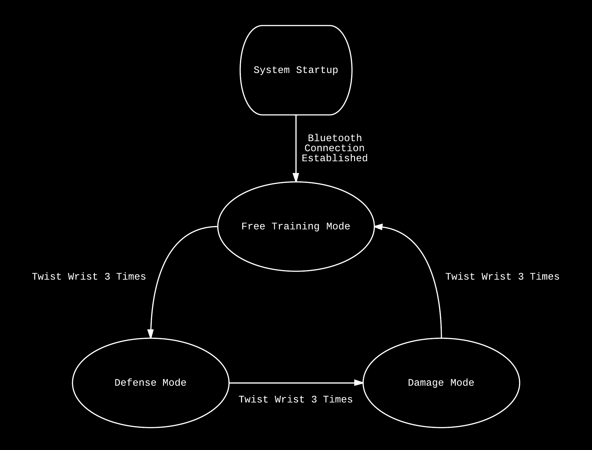
We realized that athletes and coaches didn't have the time to muck around with buttons and switches to configure the
Fight Coach, and so we needed to implement some kind of gesture-recognition so that the user could change the operating
modes of the Fight Coach while his gloves are still on. But since we could not employ roll pitch and yaw, we needed to
implement a gesture control that uses only the raw data available do us: acceleration along the XYZ axes (m/s^2 ), and
rotational acceleration around the XYZ axes (rads/s^2).
By measuring the rotational acceleration of a user's wrist (rotational acceleration around the x-axis), we have found that
applying thresholding and integration on that measurement is a reliable way to command the Fight Coach to switch between
its different modes. In other words, when the user twists their wrists hard enough and long enough, the Fight Coach switches
between its different modes and begins the training sessions after a 10 second delay(during which the user has time to
mentally and physically prepare himself).
If the user twists his wrists hard enough, the rotational acceleration along the x-axis will exceed the value defined in '
xRotationThresholdStateChange', at which point the variable 'stateAccumulator' begins to wind up. Once the stateAccumulator
winds up past the value stored in the variable 'stateAccumulatorChangeThreshold', the system cycles to the next state and resets
the stateAccumulator.
The video below shows a demo of defense mode
Defense mode is a feature that is meant to simulate a user's reaction time in response to a threat. Defense Mode runs for 2
minutes (simulating the length of an amateur boxing round) and randomly sends instructions (via the matlab audioplayer
object) to the user to either slip left/right, duck, or move backwards every second. Fight Coach then measures the time that
it takes for the user to respond to the threat. Defense Mode also penalizes the user for dodging in the wrong direction. The
default penalty value is 1 second, but adjusting this is simply a matter of setting the penaltyTime variable in
monitor_rawdata.m.
The 'tic' and 'toc' functions in Matlab were used extensively for all timing purposes in our code. These are functions in Matlab
that allow you to start and stop a stopwatch. Furthermore, by creating multiple stopwatches, you can create rather complex
timing routines. In defense mode, at least 3 timers were used:
• dodgeTimer: is a stopwatch that measures the time it takes for the user to dodge in response to an audio instruction to
dodge 'left', 'right', 'duck' and 'back'.
• roundTimer: is a stopwatch that measures the duration of the round. If the duration surpasses 120 seconds, Fight Coach
indicates that the round is over by playing a the sound of a bell (how sounds are played will be discussed in the Playing
Sounds section).
• beginTimer: is a stopwatch that allows 10 seconds to elapse between the time that a user entters defense mode, and
the time that the round begins. 10 seconds after the user enters defense mode, the audioplayer will tell the user "3,2,1
BEGIN!"
To measure whether or not the user had successfully, or unsuccessfully dodged according to the Fight Coach's instructions,
thresholding techniques were applied (similar to the ones used to switch between Defense, Damage and Free Training mode).
In particular we use a switch ( switch(dodgeMoveInstruction) ) to take into account all of the possibilities that can occur after
Fight Coach tells the user to dodge, but it all boils down to this: if the acceleration of the user is correct with respect to the
dodge instruction that was called - i.e if the Fight Coach tells the user to dodge left and the z-axis acceleration exceeds the
zDodgeAccelerationThreshold - then Fight Coach will record the reaction timing of the user and store it in reactionTimeData[].
Otherwise, if the acceleration of the user exceeds any of the other thresholds (that are for dodging right, ducking and dodging
backwards), then the user is penalized.
Also, if the user doesn't exceed any threshold (by standing completely still), then dodgeTimer simply times out at 1 seconds
and Fight Coach record
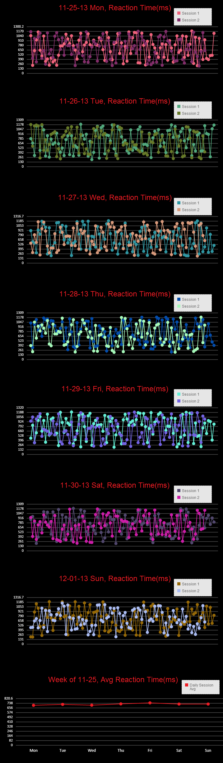
All of the data recorded by defense mode is stored in the array reactionTimeData[], which is converted into .csv format at the
end of the round via csvwrite(fileName,reactionTimeData) (as well as the time and date of the round) so that the user can
build a database of his defensive capabilities (as shown in the Results section).
Damage Mode
The video shows a demo of damage mode.
Figure 9 below shows a flow chart of damage mode (higher resolution figure available in appendix)

The goal of Damage Mode is to see how much damage the user can dish out over a round. Rather than indicate the energy of
the user's strikes, we decided that it would be better to implement our own system, the Damage points system, that not only
takes into account the force generated by the user (the acceleration of his fist), but also rewards the user for connecting
multiple consecutive strikes.
The damage points system came from the dissatisfaction of using units for energy (joules), or force (G's/Lbs) to describe the
offensive capabilities of an athlete. We found that using Joules was inaccurate (since it is a function of the weight of the
athlete), while using force doesn't take into account duration or total energy that is generated during a training session
Damage points: how to measure strike damage and reward combos
Similar to the thresholding techniques described in the previous sections, Fight Coach only registers strikes once the
acceleration of the user's gloves exceeds the the threshold 'yDamageAccelerationThreshold'. The difference between the
measured acceleration of the hand and the threshold of the strike is added to the variable 'damageOutput'. Thus, the harder
you hit, the larger the difference between the measured forward acceleration of the glove 'Y(wndw) ' and the threshold
yDamageAccelerationThreshold. The value of damageOutput is displayed by the Damage Bar, which increases in height as the
user launches strikes, and decreases when he doesn't strike
During the time that the acceleration of the gloves is below the threshold acceleration for damage mode (the user's hands
aren't really doing anything), damageOutput (and hence the Damage Bar) begins to decrease linearly with time at a rate
determined by 'damageOutputDecayRate'. What this means is that the Damage Bar increases as the user strikes, and
decreases as the user stops striking (or strikes at a slower pace), effectively indicating the damage output rate of the user.
Furthermore, since Fight Coach only increases damageOutput when it detects that the acceleration of one of the user's hands
exceeds the yDamageAccelerationThreshold, this means that the full value of the acceleration coming from your other hand
will be added to damageOutput (yDamageAccelerationThreshold has already been exceeded by one hand, and so the full value
of the accleration from the other hand is added to damageOutput). In other words, since the thershold acceleration value isn't
being deducted from the subsequent strikes, this means that once you enter a state where the
yDamageAccelerationThreshold has been exceeded, all successive strikes that exceed yDamageAccelerationThreshold add
more to your
We wanted Fight Coach to evolve throughout the progression of the training session, so we implemented a feature called
Limit Breaker, inspired by Final Fantasy, the popular video game series.
Once the damage output of the user exceeds a predetermined level (for development purposes this was set to be a quarter of
the maximum allowable damage points of 1 million, but this can be set to a higher amount) the damage bar changes color from blue to
red, and plays the Ryu theme from Street Fighter to motivate the user, and indicate that his session has reached a
satisfactory intensity.
Playing Sounds
What really sets Fight Coach apart from other accelerometer/gyroscope based athletic monitoring devices is its ability to
interface with the user via sound. This is accomplished by using audioread(fileName.mp3) to read music data into an array,
and then creating an audioplayer object from that array via audioplayer().
We found that the microphone on the iPhone5 created very good voice recordings, and used it to create the voice instructions
for Fight Coach.
Sounds for easter eggs such as the "HADOKEN" were downloaded from streetfightermedia.com ( http://tinyurl.com/n4pdcat)
Music for the limit breaker was provided by " Ryu's Theme " from the Street Figher 4 Soundtrack (Youtube Standard Licensing
CC-By)
Software Debugging and testing: Optimizing Real-time rendering with Matlab
To develop Fight Coach's software, we first started by working on the MCU side of things (getting i2c and UART to work
properly before moving on to develop the application on Matlab. However, we found that one of our most costly software
bugs was trying to figure out how to get real-time rendering working in Matlab.
Plotting in real-time in Matlab is computationally costly, and there are several techniques that you can use to optimize graphics
performance. When we first started using Matlab to plot out accelerometer and gyroscope data coming from our hardware,
we noticed a significant delay between the time that the gloves were moving, and the time that it took for our Matlab
program to register the movement. To fix this required a number of changes, and we list the following optimizations which
might be useful to anyone that is interested in plotting multiple pieces of information in real time:
• Using set instead of resfresh or plotting again
o Using the 'plot' function is costly: it redraws and recreates a plot object with every call, making it unsuited for real-
time plotting of data. A nice article here (http://stackoverflow.com/questions/13102654/how-should-i-update-the-
data-of-a-plot-in-matlab) shows the different performance that you get. After you use the 'set' function to update your
data, you need to use the 'drawnow' function to update the user-interface objects.
• You want to limit the number of times you use 'drawnow' since updating all of your figures is costly, and can hurt real-
time performance (calling it too often in the main loop can cause a significant delay). We call it once per loop iteration, but
for better performance you can call it once every two loops (or three)
• Limiting the size of your figures, or pre-defining the size
o We noticed that the performance of the Matlab graphics is related to the size of your figures. Try predefining your
axes and window size, and set automatic-mode properties to manual as shown in this article
(http://www.mathworks.com/help/matlab/creating_plots/optimizing-graphics-performance.html).
Results
Execution speed
One of the original goals of Fight Coach was to ensure that statistics from defense mode and damage mode were available to
the athlete in real-time. At first we were worried that the baud rate of the UART connection between the MCU and the blutooth
module would be too slow (at 9600, it allows you to send 1 sample of accelerometer data every 10 msecs) , but then we
realized that the bottle neck for execution speed was actually the Matlab graphics. After some optimization, we were able to
get Matlab to render the figures in real-time (as shown in the videos in the defense mode and damage mode sectinos),
although this performance is compromised when we use bigger figures i.e when we try make the GUI full screen, a noticable
delay is introduced on the order of 1 second.
Power mangement and battery life
We calculated the battery-life of the Fight Coach to be at around 2-3 hours of continuous operation (continuous
transmission). Leaving the Fight Coach in free-training mode (in which the gloves are constantly transmitting their MPU-6050
data to the Matlab terminal), we found that approximately 3 hours elapse before the Fight Coach dies out. We also found that
while not transmitting, the Fight Coach lasts over 7 hours in standby.
Safety Considerations
Naturally, this project involves the user's participation in combat sports, and involves the risks associated with those activities.
It is the user's responsibility to practice safe sparring methods with the appropriate protective gear. Fight Coach is designed to
work in sparring scenarios (full-protective gear) as well as solo training (with punching bags and muay thai pads). It is
important to note that such scenarios are significantly safer than competition scenarios, and under no circumstances should
the use of this project encourage the user to ignore safety measures during training.
Interference
Since Fight Coach relies on wirelessly transmitting data via Bluetooth, all interference considerations are handled in the
Bluetooth stack. As mentioned in the Relevant standards section, our bluetoth module is a class 1 FCC-approved transmitters
that operates in the 2.4GHz ISM band with minimal intereference to neighboring devices.
User Friendliness
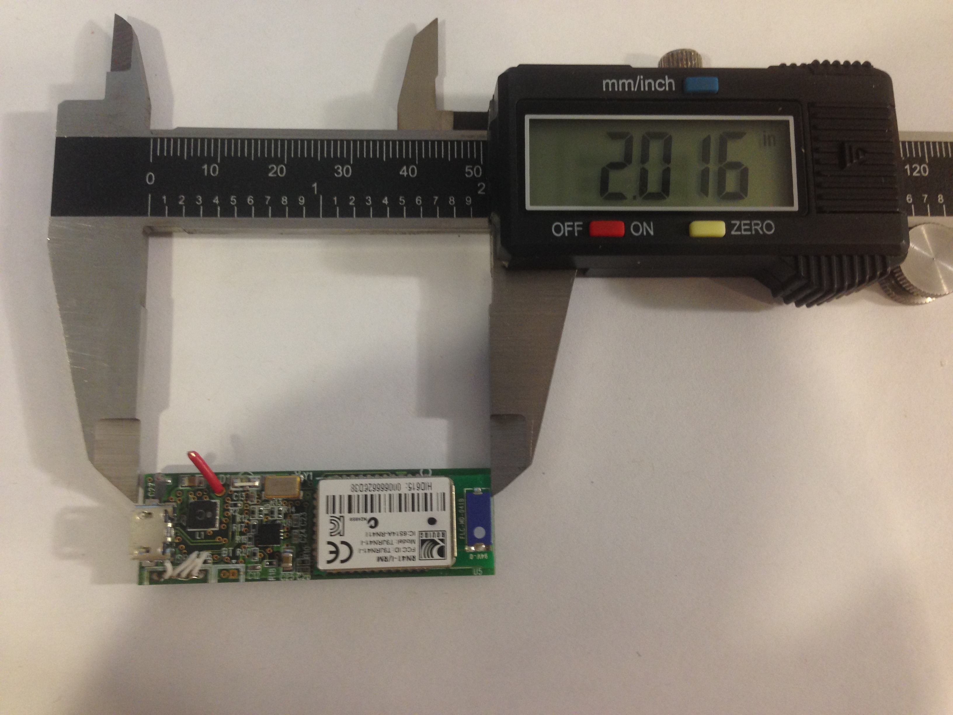
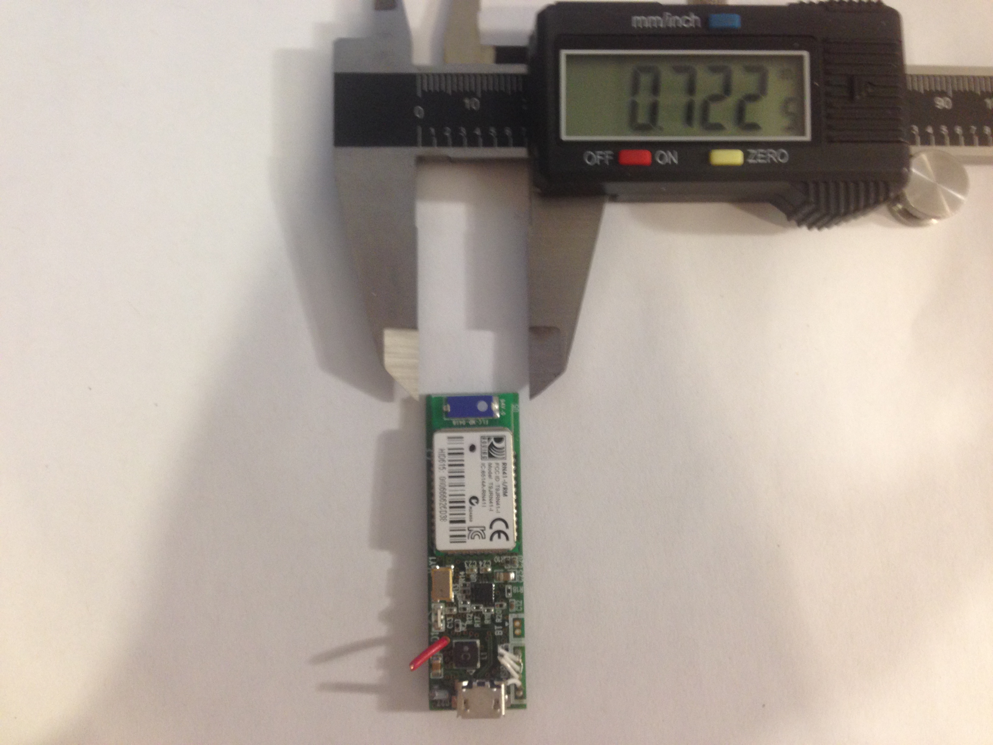
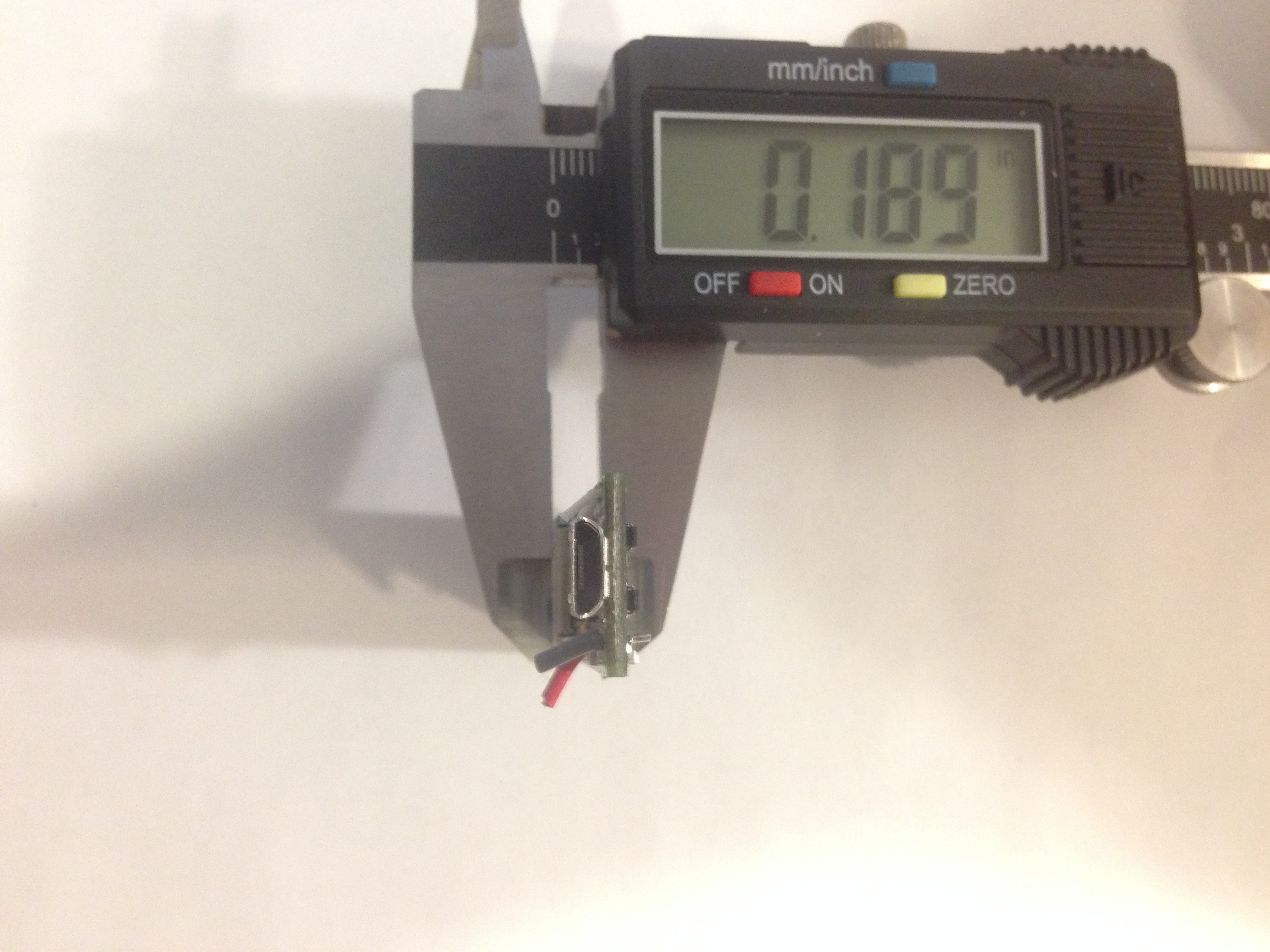
We were able to make the Fight Coach small enough and light enough to be seamlessly integrated into a boxing glove.
Weighing less than 5grams (4.98g)(battery+board together) and with a footprint of 2 by 1 inches, we can say that
incorporating the Fight Coach into a user's equipment (gloves in our case) makes very little difference to the feel and weight
of his equipment.
Figure 10 below shows pictures of caliper measurements of the size of Fight Coach
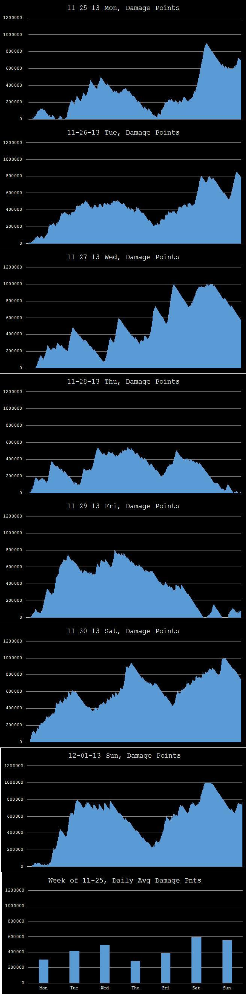
Data Logging
We were able to successfully implement Data logging witht the Fight Coach by creating .csv files from the data that is
generated by the user during his workouts. Figure 11 (link below, and in the appendix) shows statistics that were made using data that was
generated over the course of a week.
Future considerations and Revisions
Final Analysis: Results vs expectations
We met all of our original goals of displaying damage output and defensive capabilities, although real-time performance is
compromised by the size of the figures that are being updated in Matlab. We were able to measure the athlete's ability to
dodge, and give them feedback on their damage output, all in a package that is lightweight and seamless, and water-resistant.
However, we were not able to implement a feature that could tell the user how many uppercuts, hooks, and crosses, as that
would require more complex machine learning algorithms. The following section descibes the improvements that could be made if time permits.
There are several improvements that could be made to the demoed version of the Fight Coach. Some of the improvements
that could be made were features that were originally inteded to be implemented, but due to time constraints, could not be
implemented. If given the opportunity, we would like to add the following features into Fight Coach:
• 3D printed case for enclosing Fight Coach, making it easier to integrate into shin guards, boxing gloves etc.
• USB bootloader: we originally chose the atmega32u4 because its factory default bootloader allows the user to program
the MCU via usb (without the need for ISP).
Specifically, to enable usb-programmability on the atmega32u4, you need to have a switch that forces the bootloader to
execute (by grounding pins 33). Power management based off sparkfun Lipo charger
•Incorporating USART for Bluetooth for more efficient data usage.
•Using machine learning to incorporate more advanced gesture-recognition i.e being able to differentiate between different
strikes and counting the number of different strikes
Ethical Considerations
According to the IEEE code of ethics, we did our part to complete this project while maintaining safety, ethical, and
professional standards. As shown by our progression from zero, to a finished, working prototype, we strived to improve our
technical competence. During the course development, we made the proper attributions to those who had given us aid, and in
particular, credited the works of Davide Gironi, Sparkfun, and Peter Fleury for their contributions to Fight Coach.
During the time that we created Fight Coach, we never accepted any bribes, in accordance with the IEEE code of ethics.
By combining our love of sports, with our engineering knowledge , we have demonstrated our goals to improve the
understanding of technologys and its appropriate applications. By acknowledging that Fight Coach is naturally a product that is
involved with dangerous sports, we have shown that we are aware of the safety consequences of such a product like Fight
Coach, and believe that by disclosing the factors that contribute to safe operation, that the public is ultimately better off.
The ECE 4760 lab is a diverse place, with students hailing from all nationalities and ethnicities. The acceptance of race, religion,
age, sex, and nationality was embodied by the willing aid that we had received from other students, the aid that we returned
in kind.
Intellectual Property Considerations
The development of our code and hardware would not have been possible if it weren't for the availability of advice, source
code and schematics of other engineers and developpers. Specifically, we would like to cite the following
• Power management was inspired by:
o Sparkfun Power Cell LiPo Charger/Booster licensed under Creative Commons Attribution-ShareAlike 3.0 Unported (CC
BY-SA 3.0)
• I2C communication routine code by Peter Fleury
• mpu_6050.c, mpu_6050.h by David Gironi released under GPLv3
Patent and Legal Considerations
We are aware of patents concerning boxing gloves that measure force and impact, but none that have incorporated features
like those in Defense Mode or Offense Mode or a method to switch between those modes.
However, research showed that the Fight Coach fits into the following patents:
US Patent No: 5,723,786
Boxing Glove Accelerometer
Abstract
These and other objects are provided by a novel boxing glove impact measuring system. The boxing glove impact measuring
system includes a boxing glove body and an impact measuring device disposed in the boxing glove body. The system also
includes an impact display device.
US8221291 B1
Athletic equipment including a health and/or impact sensor
Abstract:
Athletic equipment is provided including sensors to monitor the effectiveness and health of the athlete. Contact sensors
identify stresses or impacts in real time, and interactively, during the training or competition. Concurrently, a health sensor,
obtaining and transmitting indicia corresponding to the physical condition of the athlete (such as heart rate, blood pressure,
etc.) can be communicated simultaneously and synchronously with the monitored stress or impact date for use in optimizing
athlete performance or monitoring athlete physiology. Such data can be transmitted to a remote location as well. In either
case, such information can provide a system for optimizing athlete performance, rather merely tracking historical information.
Real time analysis and physiological-performance correlations can be achieved, thereby minimizing the need, or extend of an
iterative training regime.


Track your combat ability
FIGHT COACH