"An acoustic wayfinding device with haptic feedback for the visually impaired"
project soundbyte
Our acoustic wayfinding device utilizes ultrasonic range finders and haptic feedback to facilitate indoor navigation for the visually impaired. The technique of acoustic wayfinding uses auditory cues, such as sounds from the natural environment or sounds created artificially, to determine an individual's surrounding physical space for the purpose of navigation. Our device is an automated and subtle implementation of this technique that uses pulses of inaudible (to humans, at least) frequencies in the ultrasonic range as opposed to taps on the floor with a cane or clicking noises made by the tongue; our device also works in noisy environments where it is typically difficult to discern auditory cues.
Our device consists of an ergonomic head-mounted navigation system with a wearable tactile sensor connected via a long flexible wire. Our device instructs the user to turn either left or right depending on the presence of obstacles in the device's field of view. The device is supplemented with a tactile sensor that mimics a "Hoover" cane (a white cane commonly used by the visually impaired as a mobility tool) which the user can use to scan for obstacles not detectable by the head-mounted sensors. This hands-free device is battery powered which allows users to navigate confidently without loss of mobility.
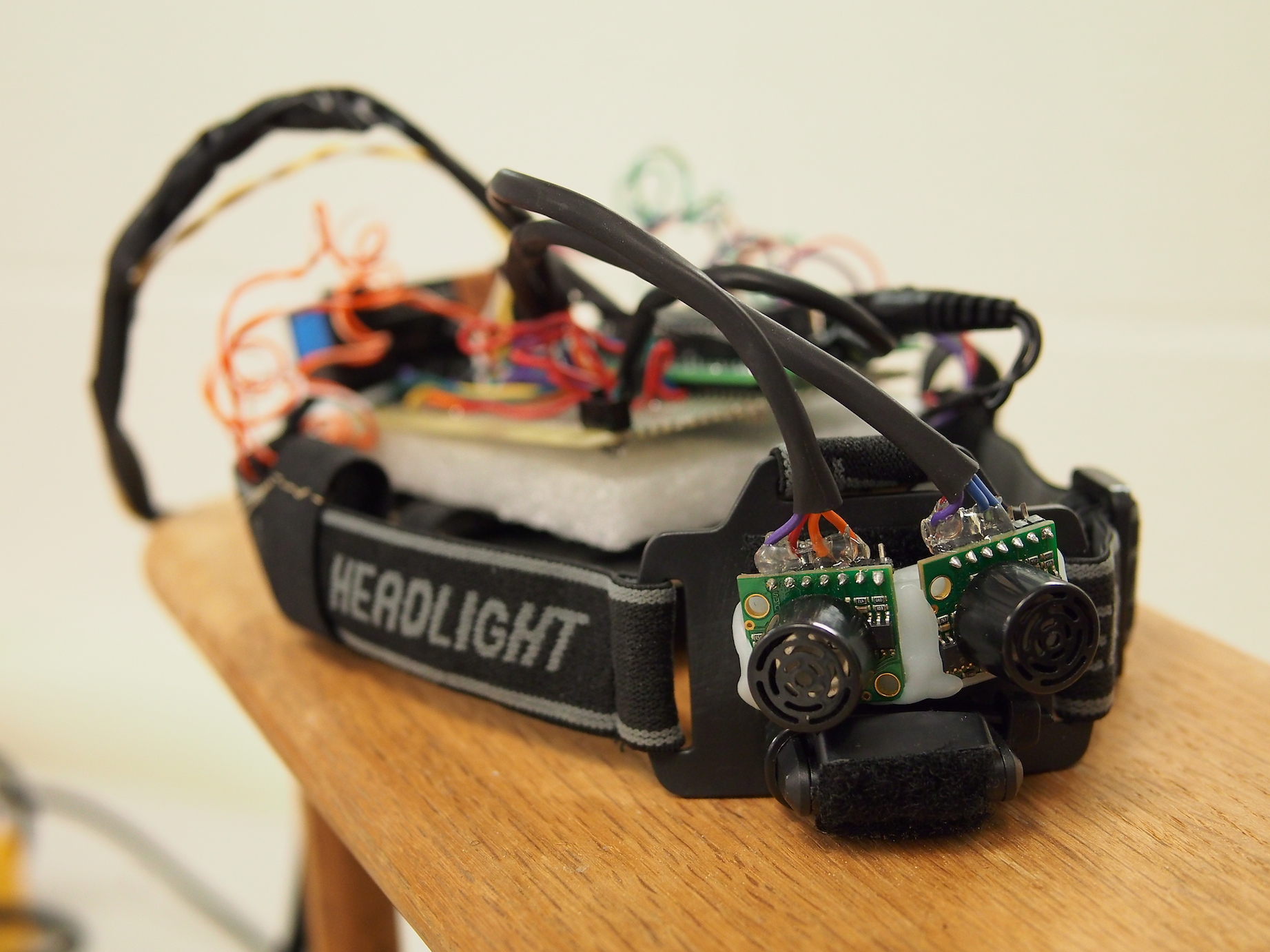
The finished product.
High Level Design top
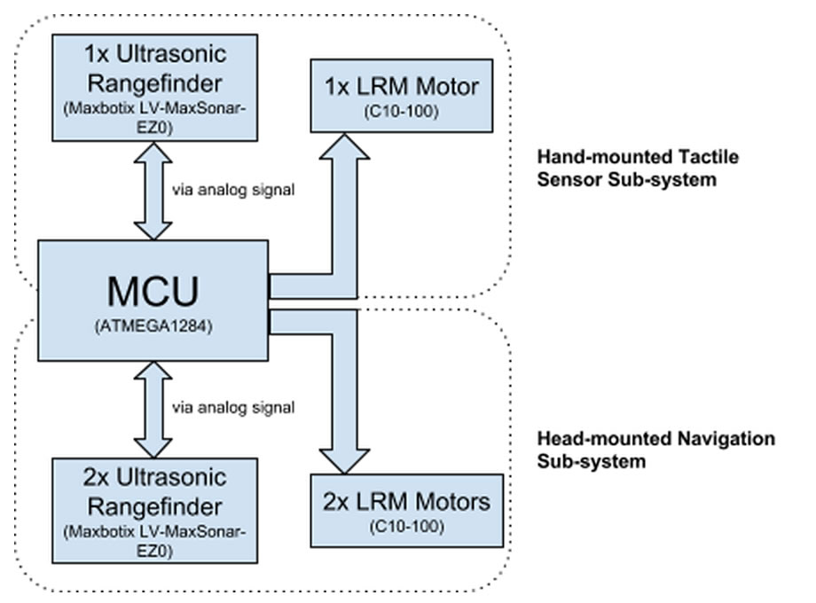
Figure 1: High-level block diagram
The ultrasonic wayfinder is comprised of two main wearable sub-systems: a head-mounted navigation sub-system, and a hand-mounted tactile sensor sub-system (see Figure 1 for a high-level overview). The head-mounted navigation device is used for spatial sensing and directional navigation, while the hand-mounted tactile sensor is used for sensing obstacles in close proximity to the user below eye-level, similar to a “Hoover” cane.
The head-mounted navigation system consists of two ultrasonic rangefinders and two vibrating motor discs. The rangefinders are capable of detecting obstacles up to 6.45 meters away with a field of view of about 120 degrees. The head-mounted system instructs the user to turn left or right using one of the two motors mounted on the back of the user’s head.
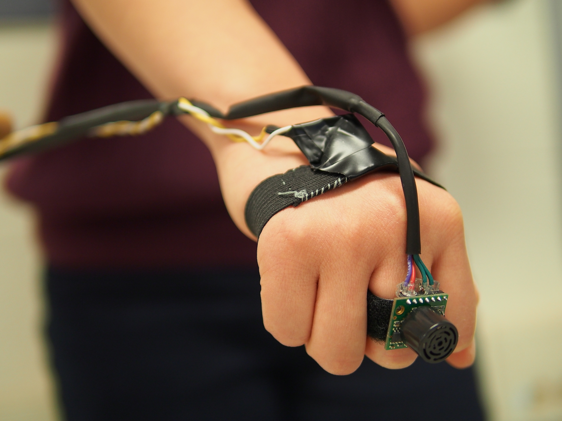
The hand-mounted tactile sensor consists of one ultrasonic rangefinder and one motor that the user can wear on his or her hand. The tactile sensor allows the user to “scan” for obstacles below eye-level (typically out of the range of the head-mounted sensors) by sweeping his or her hand laterally, similar to how one would use an assistive cane. The rate at which the motors pulse is proportional to the distance of the obstacle from the user -- the closer the object, the more rapid the pulses.
Rationale and Inspiration
While brainstorming ideas for our final project, we first browsed previous work done on Hackaday. We were inspired by a project that used a robot as a safe and cost-effective alternative to guide dogs (see link). This device helps the visually impaired avoid obstacles using 3D mapping from four cameras. Like a guide dog, the robot pulls the user in different directions to avoid detected objects. We thought this was a great idea, but thought it would be better to have a wearable guidance system that would be more subtle, less cumbersome, and have less interference with the user’s mobility.
We decided to create a head-mounted system for object detection to facilitate indoor navigation using the technique of acoustic wayfinding. With two ultrasonic rangefinders mounted on the head and a third rangefinder in the user’s hand, this system provides an intuitive set of haptic feedback instructions to tell the user what direction to walk towards. These haptic instructions are provided by two vibrating motors in the headpiece and a third motor on the user’s hand.
Past ECE 4760 project groups have created similar devices that utilize ultrasonic rangefinders for navigation. However, many of these past devices have several shortcomings of their own, such as limited range, limited field of view and noisy sensor outputs leading to incorrect feedback. Furthermore, none of the previous projects have devices that could detect obstacles that are most hazardous to a visually impaired person -- obstacles below the eye-level that could potentially cause the visually impaired person to trip and fall.
As such, we developed a device that combine various aspects of past projects that worked well in a more cohesive and ergonomic package. On top of that, we extended the device with an extended tactile sensor that allows the user to detect low-lying obstacles in an intuitive and familiar manner by mimicking the use of a “Hoover” cane. We also decided to use haptic feedback as we did not want to interfere with the hearing of the user -- visually impaired people are typically more reliant on their sense of hearing in navigating the physical space. Haptic feedback would also allow our device to be used in noisy environments.
Background Math
The ultrasonic rangefinders work by emitting an ultrasonic pulse and timing the duration it takes to receive the pulse reflected off an obstacle. As the speed of sound in air is approximately 340m/s (disregarding variations in humidity, pressure, interference, etc), the distance of the obstacle can be determined by (340 * (measured duration))/2.
Logical Structure
Our device uses the TinyRealTime kernel to provide real-time functionality; this allows our device to perform certain tasks simultaneously, such as allowing the user to use the extended tactile sensor independently of the head-mounted navigation system.
There are real-time tasks for the sequential reading of each ultrasonic rangefinders and two other separate tasks for the navigation logic -- one for instructing the user to either turn left or right, and another for the tactile sensor.
All the readings are median filtered so as to remove discrete noises caused by interference (typically from external sources) or noises in the sensor circuit.
Hardware Tradeoffs
We decided to use commercial ultrasonic rangefinders with a large range and a wide beam pattern at the expense of resolution and cost as they would be most suited for our device -- the large range ensures that we can detect obstacles far away and the wide beam pattern gives us a greater field of view.
We initially had the third ultrasonic rangefinder mounted on the head tilted towards the ground to detect objects below eye-level and sudden changes in elevation, which could be indicative of a flight of stairs. However, we found that we got erratic readings that depended greatly on the nature of the obstacle surface.
We decided to use ultrasound as opposed to infrared for ranging, since ultrasonic characteristics are best suited for our device. Our device requires larger ranges than most infrared transmitter/sensor setup can detect, and was designed for use in indoor environments where interference from other infrared-emitting sources can pose a problem.
Software Tradeoffs
The median filter we employed uses a window of size 3. While a larger filter size would be more effective in removing noise, it would require more computational complexity (especially since the filter is applied to all the rangefinder readings). Furthermore, we found that a size 3 median filter was sufficient in removing most of the erroneous readings.
Existing Products
There have been similar head-mounted assistive devices developed in the past, such as SonicGuide (developed in 1974) and the KASPA system (developed in 2002). KASPA is an updated version of SonicGuide, using ultrasound mounted on a headband instead of on spectacle lenses. Both systems use haptic feedback to communicate with the user, similar to our device.
We also found that a past ECE 4760 project, "Ultrasonic Haptic Vision System", used a similar concept using an ultrasonic rangefinder and small vibrating motors.
Our system differs from these other devices in execution and concept. Our device supplements the head-mounted navigation system with the use of a hand-mounted tactile sensor, which acts as a virtual cane, which is intuitive for visually impaired individuals.
Software Design top
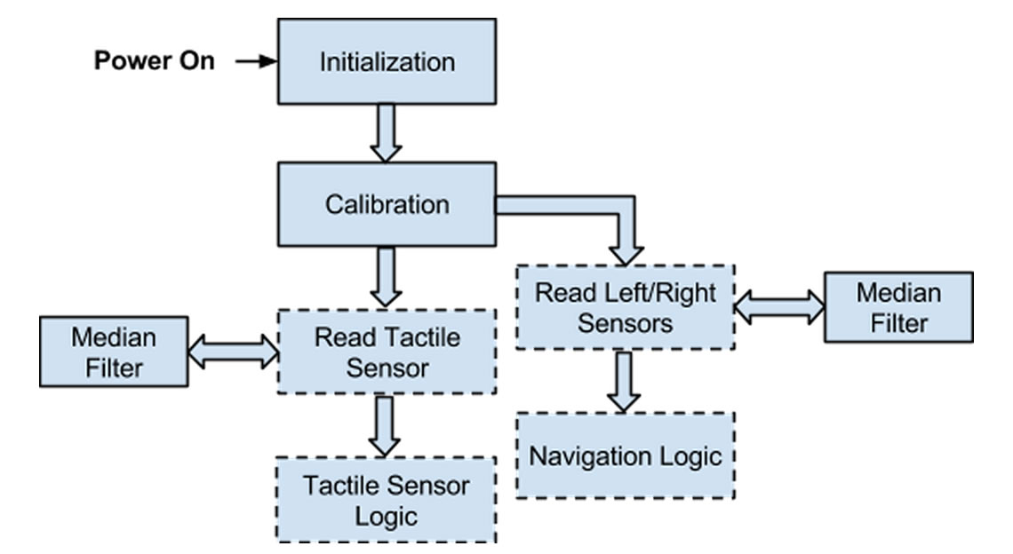
Figure 2: Program Overview (Functions in dashed boxes are real-time tasks)
Initialization and Calibration
As shown in Fig 2 above, upon powering on the device, the program first initializes the ADC and TRT kernel, and creates the necessary semaphores and real-time tasks. The ADC is initialized by configuring the appropriate registers, mainly to left-align the ADC values in the data registers (to convert the measurements from 10-bits to 8-bits as we did not need 10-bits resolution and it was easier to read off one register) and to set the prescaler to 32 (which we determined experimentally to provide the best compromise between sampling frequency and resolution for our purpose).
The program then enters the calibration mode in which it determines the threshold for the tactile sensor based on the height of the user. The user is required to hold the tactile sensor by his or her side while the program performs the initial calibration. The program takes three calibration readings at around 140ms apart, and then chooses the the median value as the calibrated value to remove any outlying readings that may arise due to interference or noise.
The tactile sensor threshold is determined to be sqrt(2) * calibrated value as we assume that the user will most often be holding the tactile sensor at a 45 degree angle (like how one would when using an assistive cane) such that the hypotenuse would be given by sqrt(2) * (height of triangle).
Obtaining Range Information from Sensors
There are three separate real-time tasks for reading from each of the ultrasonic rangefinders from the microcontroller’s ADC inputs.
The main issue we had to deal with was the simultaneous use of all three ultrasonic rangefinders. Semaphores are used to ensure that the rangefinders are ranging sequentially such that they do not interfere with each other (e.g. one rangefinder receiving another rangefinder’s reflected pulse). Delays are used to ensure that the rangefinders have sufficient time to range; particularly, a delay of 50ms is used as the rangefinders require 49ms to obtain a range reading.
Range information is obtained from the sensors by calling the adc_read function which selects the correct ADC pin by setting the right bit values in ADMUX, starts the conversion, and then returns the 8-bit range value from the register ADC. The 8-bit range value from the ADC is converted to distance in meters using the following equation:
![]()
The first term converts the ADC bit value proportionately from 0 to 255 (since the value is 8-bits) to 0 to 5V. The second term converts the voltage to distance in inches -- according to the MB1000 datasheet, the analog output from the sensor corresponds to (Vcc/512)V per inch. Finally, the third term converts the distance reading from inches to meters.
Median Filtering

Figure 3: Raw range data with voltage level corresponding to detected range; also shows impulse noises
All ultrasound rangefinder readings are median filtered (with a filter of size 3) to remove impulse noises. The median filtering was effective as most of the noises encountered in the ranging data were impulse noises (see Figure 3).
We found that the most frequent cause of these noise is the sudden changes in ranges detected when the rangefinder ranges multiple objects of different distances. For instance, when the rangefinder is pointed slightly off-centered towards a person standing 3m away from the sensor (with a wall 2m behind the person), the range data will change abruptly from 3m to 5m, creating spikes in the range data similar to those that we see in Figure 3 above.
Another common source of impulse noises are the unintended reflections caused by overestimating the distance of an object when the reflected pulse bounces off the ground before reaching the rangefinder.
Wayfinding Logic
There are two real-time tasks responsible for the wayfinding aspect of the device: the navigation and tactile sensor logic.
The navigation logic checks for the presence of obstacles in the fields of view for the left and right rangefinders. If an object is found within our defined threshold of 2m in either field of view, the corresponding motor will buzz (obstacle on right side -> buzz right, obstacle on left side-> buzz left), indicating to the user the direction of the obstacle. If obstacles are detected by both the left and right rangefinders, then the user will be notified of the direction of the obstacle closer to the user (which is likely the obstacle more critical or hazardous to the user).
The tactile sensor logic checks for the presence of obstacles within the threshold as determined by the calibration process. Obstacles at a range below this threshold are obstacles that would typically be detected when a visually impaired person scans his or her immediate surroundings using a "Hoover" cane, i.e. objects that are large enough to cause the user to trip and fall, or objects that can collide with the user. The tactile sensor logic also scales the intensity of the vibrations proportionately with the proximity of the obstacles.
Both the navigation and tactile sensor logic functions linearly interpolate the intensity of the vibrations according to the distance of the obstacles from the sensor. This is done by varying the duration of each pulse using the equation
![]()
where the values of the multiplier were experimentally determined to be 30 for the navigation logic and 20 for the tactile sensor logic. This was chosen such that the minimum detectable range of approximately 0.15m will give 200ms and 133ms for the multiplier values of 30 and 20 respectively. Longer pulse durations (and hence higher pulse intensities) were used for the head-mounted motors as compared to the hand-mounted motors as we found that the head is less sensitive to vibrations compared to the hand.
Real-time Scheduling
All the ranging and navigation tasks are in real-time so that the device gives the illusion that the head-mounted and hand-mounted sensors are working independently and simultaneously.
All the real-time tasks but the navigation logic are executed with the deadline equaling the release time. This means that the tactile sensor logic task and all three ranging tasks run in the order in which they are released (i.e. not in a true "real-time" fashion) and have priority over the navigation logic. The navigation logic is also running at a frequency of 300ms compared to 250ms for all the other tasks. This is because the navigation logic can still function fairly accurately while using range data that are slightly "old".
The ranging tasks for all three rangefinders repeat at every 250ms. We determined experimentally that this is approximately the minimum time the task requires to complete the ranging (which takes 49ms according to the datasheet), to convert the range to meters, and to save the range for median filtering.
Hardware Design top
Microcontroller
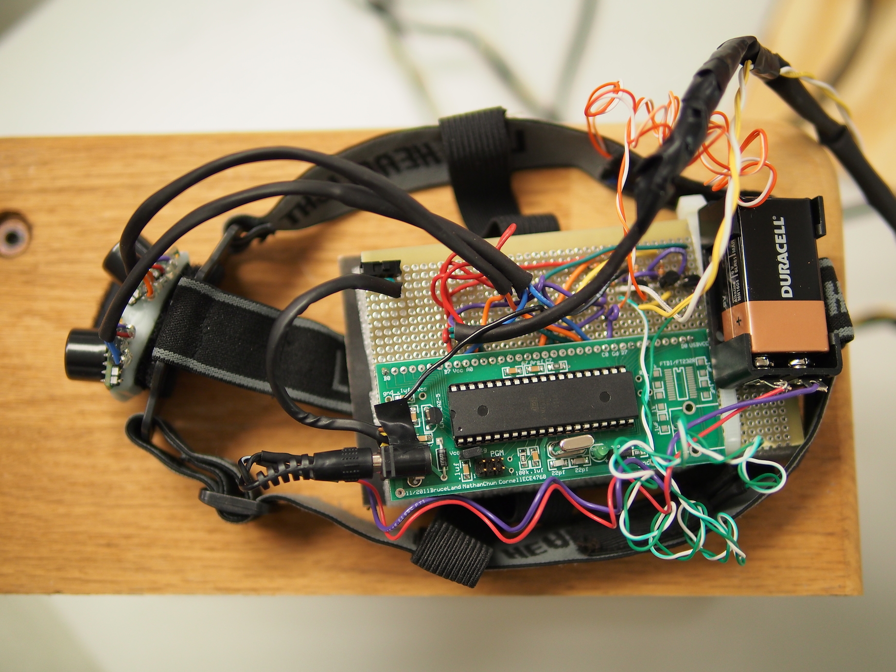
The microcontroller used for the ultrasonic wayfinder is the ATmega1284 mounted on a custom PCB. We initially went with the ATmega1284 as we expected to use Timer3 to accommodate the use of the pulse width output from the ultrasonic rangefinders. However, when we ultimately decided not to use the pulse width output, we already had most of the device built. With the given time time constraint of this project, we decided to use ATmega1284 to ensure a finished product.
Motor
The motors used were vibrating mini disc motors (part no. 1201) from Adafruit. These motors are small disc-shaped motors that are adhered to the head-band and the hand-strap of the device.
The motors operate when driven between 2V to 5V, with a 40mA current draw at 2V and a 100mA current draw at 5V.
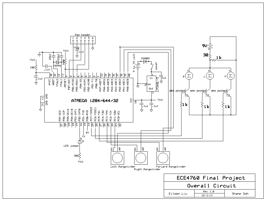
We decided to drive the motors directly from the 9V battery via a simple control circuit through the use of 2N3904 NPN BJTs. We found that even though we could drive the motors in pulses at 5V from the microcontroller's port pins, we were concerned that driving the motors for extended durations of time would draw too much current (peak current of ~100mA) from the MCU and would cause the on-board voltage regulator to reset the MCU.
The control circuit uses a control signal from an MCU output pin into the base of the BJT (see schematics in Appendix), with the emitter connected to ground and the collector connected to the negative terminal of the motor. The positive end of the motor is driven from a potential divider circuit that provides it with 4.5V. Port pins C.6 and C.7 are used to control the left and right motors respectively.
The motors also did not need to be isolated from the microcontroller as we did not find any evidence of the motors generating large inductive spikes.
Ultrasonic Rangefinder
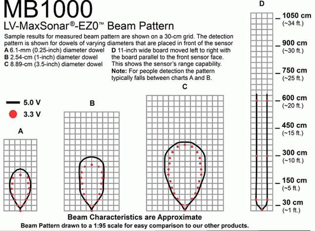
Figure 4: Beam pattern of LV-MaxSonar-EZ0 Sonar Sensor
(from the MB1000 datasheet)
The ultrasonic rangefinders we used are the MaxBotix MB1000 sonar rangefinders. We used three of these rangefinders, with two mounted on the head-mounted navigation system and one used for the hand-mounted tactile sensor.
Our two main criteria for choosing an ultrasonic sensor are to maximize range and beam width. As shown in the beam pattern diagram in Figure 4, the MB1000 sensor has a maximum operating range of 6.45m and a beam width that is wide enough such that two of such sensors placed next to each other would be able to cover as wide a field-of-view as possible.
We powered all the three sensors with 5V to get as much range and as wide a beam pattern as possible. We then controlled the ranging of the sensors through control signals from three output pins from the MCU (ports C.1, C.2 and C.3) into the RX pin of the sensor.
The MB1000 sonar rangefinder supports three different outputs: 1) analog voltage with the voltage corresponding to the ranged distance, 2) pulse width output with the width corresponding to the ranged distance, and 3) ranged distance in RS-232 format.
We initially tried to use the pulse width output but decided against it as we intended to use the TinyRealTime kernel which uses Timer1 for scheduling. This would in turn leave us with Timer3 (on the ATmega1284) as the only other timer that can be used with an input capture register. We could have implemented our device by reading from all three sensors into one port pin using a multiplexer, but we decided that this was too cumbersome an approach.
We also considered using the RS-232 format for its simplicity in implementation. We intended to use both the hardware UART and one software UART (using the bit-banging technique from Lab 3 - infrared lock and key). However, while we managed to get the device to output to UART0, we were not able to read the bit stream correctly.
In the end, we chose to use the analog voltage output.
Power
The MCU and the motors are powered using a single 9V battery in a 9V battery holder. We found that a single 9V battery was sufficient in powering our device for extended use.
Each motor has a resistance of 50 ohms and is driven at 4.5V, effectively drawing 4.52/50 = 0.405W each, with three motors drawing 1.215W altogether. Additionally, the motors are driven in pulses, with the longest pulse being around 200ms.
Results top
Speed of Execution
Our device detects objects quickly - in our software, we give each rangefinder 50 ms to turn on, detect the closest object in its field of view, and turn off. According to the rangefinder data sheet, it takes 49 ms for a rangefinder to take a range reading. The three sensors in our device range sequentially, causing a slight delay before the haptic feedback is updated. However, this delay is small and unnoticeable. While using our device, the user is still able to quickly detect and avoid nearby obstacles while walking indoors.
Accuracy
The ultrasonic rangefinders can detect objects with 1 inch resolution between 0 inches to 254 inches (6.45 m), according to the MaxBotix MB-1000 datasheet. While testing, we found that the rangefinders struggled to detect objects past 5 meters. However, since our device is aimed for indoor use, 5 meters is more than enough range to detect nearby obstacles. We also found that the rangefinders could detect objects with about 1 inch resolution. This was especially applicable in our tactile sensor as it allowed the sensor to detect small changes in ranges, which in turn allowed it to detect small objects such as a door knob on a door.
Each rangefinder has field of view of about 60 degrees, allowing for a total field of view of 120 degrees. In general, our device was able to detect nearby obstacles, including people. Detection of people can often be tricky, since people absorb acoustic waves. In our software, our threshold for close objects is set to 2 meters, which is one third the max distance the rangefinders can detect. The rangefinders still emit strong enough ultrasonic waves to range up to 6.45 meters, which ensures that we can detect people within our 2 meter range even though ultrasonic waves are largely absorbed by people. Sporadic distance readings were eliminated using a median filter. The accuracy of object detection was dependent on the speed of execution, which is mentioned in the Speed of Execution section.
We also converted the measurements from 10-bits to 8-bits as we found that we did not need the accuracy provided by the 10-bits resolution. This in turn made it easier and faster to read the range data (as it involves reading off just one register).
User Evaluation
We tested our device on a variety of users with minimal instructions to see if we had built an intuitive device. Our ultrasonic wayfinder performed exceedingly well during these tests when evaluated by our classmates and our instructor.
We found that most users were able to confidently walk around indoor environments with their eyes closed while avoiding most obstacles. The head-mounted sensors allowed the user to detect walls easily, while the hand-mounted tactile sensor was responsive and sensitive enough to enable the user to sense smaller obstacles below eye level that the user could have collided with. In Figure 5 below, users can be seen detecting and avoiding low level obstacles.

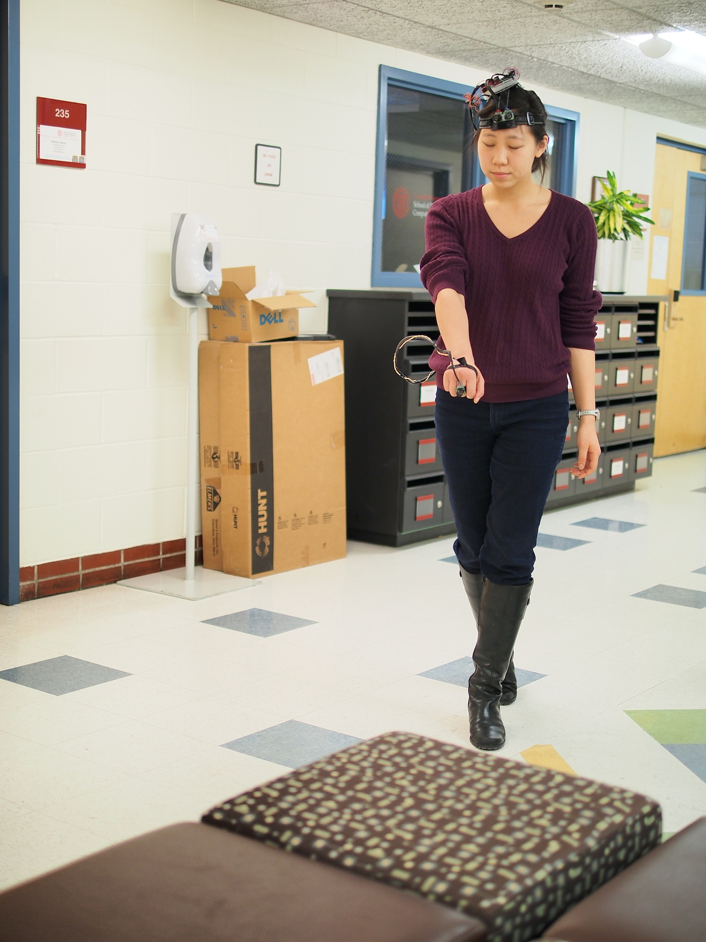
Figure 5: Users avoiding low level obstacles using hand-mounted tactile sensor
All users found the device to be very intuitive. Most were able to use the ultrasonic wayfinder with little to no instructions, suggesting that the interpolated strengths of the pulsing motors were very natural indicators of nearby obstacles and their proximity to the user.
Safety
Safety was a key concern while designing our device for visually impaired individuals. We minimized the number of loose components and exposed electronics which a user could accidentally come into direct contact with. All wires are insulated and given slack for user mobility. The extra wire lengths are coiled to prevent the user from becoming entangled during movement. The device is isolated to a 9 volt battery, which is not a high enough voltage to harm a user, except for a minor shock. The device has a power switch that turns the device on and off. The battery itself is also connected to the MCU via a removable power plug, allowing easy and safe disconnection of the device when it is not in use.
All usage of this device was conducted in a safe and controlled environment. All users were briefed prior to using the device that this device is a prototype and is not foolproof in its design. Users must exercise the same amount of caution as they would with any other assistive devices.
Interference with Other Designs
The only way another device could disrupt our device would be if there were another ultrasonic emitter nearby. Those ultrasonic waves would be detected by our rangefinders, which would skew the distances to our microcontroller. However, ultrasonic emitters are not commonly found in an everyday settings, so this is a trivial concern.
Usability
For visually impaired individuals who navigate using conventional acoustic wayfinding techniques (such as through the tapping of a cane or the clicking of one's tongue), our device provides an advantage of being usable in noisy environments where such conventional echolocation techniques cannot be used.
Additionally, while our device is designed primarily for visually impaired individuals, it can be used by sighted individuals in other settings. For example, our device can be used in environments where visibility is limited or non-existent.
The headpiece is elastic and adjustable, as is the handpiece. This allows for users with differently sized heads and hands to use this device comfortably. Our software does an initial calibration for a distance threshold for the virtual cane. This allows our device to be tailored for people of different heights.
Conclusions top
The results of our final device met the expectations we defined in our project proposal. Our prototype was capable of detecting a wide range of obstacles and providing the user with distinct and responsive haptic instructions. We believe our prototype has also clearly demonstrated the potential utility behind a novel approach to visual assistive devices.
Future Work
With additional time and resources, this device could be further developed for more ergonomic and practical everyday use. For example, we could look into using other ultrasonic rangefinders or even building our own rangefinder. Replacing our current rangefinders could allow for faster response and better resolution. This replacement could also allow us to explore how to make the sequential ranging of our sensors more time and power efficient.
We had also originally planned on using a third rangefinder on the headpiece for the detection of stairs and ramps. After initial tests with this idea, we found that the rangefinders produced sporadic readings when aimed at an angle towards the floor. With such inaccuracies, it was difficult to distinguish changes in elevation. We could potentially use infrared sensing for this purpose instead.
We would like to create a wireless hand-mounted tactile subsystem for easier mobility, with an on/off switch. There could be multiple handpieces, with potential for pieces on other areas of the body, such as the knee.
There were many unused port pins on our device (Ports A and B). In the future, we could design a smaller custom PCB with a smaller MCU such as the ATtiny to minimize the size and weight of components the user has to wear on his or her head.
In terms of software, we would like to include speed detection, in which our MCU would calculate both the distance and rates of approaching objects, calculating which obstacle is most hazardous and most likely to have immediate impact with the user.
Standards
IEEE safety standards for consumer products outline the need for a "better user interface" [ISO 9241-920:2009, "Ergonomics of human-system interaction -- Part 920: Guidance on tactile and haptic interactions"] To comply with these standards, we integrated several design features into our device. Our device is completely external and only interacts with the user via small vibrating motor discs. There can be up two motors buzzing at once, but they are isolated so only one motor per headpiece or handpiece system can buzz. This is to prevent the user from being confused by the navigation instructions. Additionally, to prevent discomfort from extended vibration in a fixed area, we pulse the motors with a duration inversely proportional to the distance away from an object instead of using a steady vibration. We also use a threshold of 2 meters to determine if an obstacle is in the user's immediate vicinity. The device overall is is hands-free which increases usability.
To facilitate the debugging process of our device, we complied with RS-232 standards to allow communication between the UART of the microcontroller and a software interface on a computer. These standards are defined by the Electronics Industries Association (EIA).
Intellectual Property Considerations
Our software was solely written by us, except for two third-party libraries: Tiny Real Time (TRT) and trtUART. TRT was written by Dan Henriksson and Anton Cervin, but modified by Bruce Land for the purposes of our ECE 4760 course. This library allowed for several real time tasks to run concurrently, with each task behaving as if it were the only program running. This allows the MCU to context switch between real-time tasks.
trtUart was written by Joerg Wunsch to allow for UART communications with the microcontroller while using the TRT kernel. This library facilitated the debugging process of our device while developing our code and hardware.
We designed our device from scratch, and did not reverse-engineer any past designs for similar products.
Ethical Considerations
During the development process of our prototype design, we adhered to the IEEE Code of Ethics. We made conscious design choices to ensure safety for the public and for ourselves while developing a quality product. While constructing our device, we constantly checked for short circuits, corrupt components, and made sure all electrical components were properly insulated. We insulated all exposed components using heat shrink, electrical tape, and hot glue where appropriate. We isolated our device to a 9 volt battery power supply, which ensures that our device cannot output more than 9 volts. Even if a person were to come into direct contact with a loose connection, 9 volts would not be able to cause permanent damage to an individual.
We gave proper acknowledgement to our project inspiration and referenced works, disclosed our data objectively with honest criticism, and constantly sought, accepted, and offered honest feedback of technical work to recognize and correct errors. We assisted our colleagues in their design processes, supporting them with constructive criticism. Most importantly, we were honest with all steps of our development process, recognizing and correcting errors when appropriate.
Another aspect of ethics that we considered was the trust that the visually impaired would have in our device. By advertising our device as an aid for indoor obstacle detection and navigation, users would expect our device to perform its defined task reliably . We made our prototype as robust as possible, using a majority of our budget on quick and accurate rangefinders and coupling them with clear instructions from vibrating motors.
We maintained a safe and controlled environment when testing our device on a variety of users. Individuals closed their eyes briefly and could open their eyes at all times. When testing, we constantly monitored users and gave a warning if they were dangerously close to an obstacle.
A comprehensive list of ethics that we followed while designing our device can be found on the IEEE website.
Legal Considerations
To our knowledge, our device does not violate any legal regulations. However, as a disclaimer, users should be advised that our device is not foolproof. Just as with any visual aid, our device can sometimes miss a certain object if the user is walking too quickly. Users must use the same amount of caution while using our device as they would using a "Hoover" cane.
Appendices top
A. Schematics
B. Cost Details
Part Number |
Vendor |
Quantity |
Price |
Total Cost |
ATMega1284 |
Lab stock |
1 |
$5 |
$5.00 |
Maxbotix LV-MaxSonar-EZ0 (x3) |
Adafruit |
3 |
$24.95 |
$74.85 |
Vibrating Mini Motor Disc (Part No. 1201) |
Adafruit |
3 |
$1.95 |
$5.85 |
Head harness |
Pre-owned |
1 |
$1 (estimated) |
$1.00 |
Large Solder Board |
Lab stock |
1 |
$2.50 |
$2.50 |
Custom PCB |
Lab stock |
1 |
$4 |
$4.00 |
Header Pin |
Lab stock |
36 |
$0.05 |
$1.80 |
Capacitors |
Lab stock |
11 |
$0 |
$0.00 |
SPDT Switch |
Lab stock |
1 |
$0 |
$0.00 |
2N3904 NPN BJT |
Lab stock |
3 |
$0 |
$0.00 |
Resistors |
Lab stock |
5 |
$0 |
$0.00 |
9V Battery Holder |
Lab stock |
1 |
$0 |
$0.00 |
9V Battery |
Amazon |
1 |
$2 |
$2.00 |
Wire |
Lab stock |
3’ |
$0 |
$0.00 |
Velcro |
Lab stock |
4” |
$0 |
$0.00 |
White foam |
Lab stock |
3” |
$0 |
$0.00 |
Total cost |
$97.00 |
C. Distribution of Work
| Shane Soh | Eileen Liu |
|---|---|
| Overall Hardware Design | Overall Software Design |
| ADC Integration | Wayfinding Logic |
| Prototype Construction/Assembly | Prototype Construction/Assembly |
| Website | Website |
| Final Prototype Testing | Hardware Schematics |
D. Code Listing
code available upon request
trtSettings.h
trtkernel_1284.c
References top
This section provides links to external reference documents, code, and websites used throughout the project.
Datasheets
References
Acknowledgements top
We thank Professor Bruce Land for his wealth of knowledge and the lab TAs for the debugging help they provided this semester.
We would also like to thank Texas Instruments and FreeScale for sending us sample components, even though they were not implemented in our final prototype.