The PICBOY32 is a robust handheld gaming platform designed for simple immersive gameplay, and convenient software development. We chose this project because devices like the Game Boy were the first computers we ever had as kids, and they were instrumental in developing our interest in Computer Engineering and Computer Science. We designed hardware to support several forms of human input devices, and also provide several outputs to the user, including sound, graphics and rumble. In addition, we use an SD card in order to store various large game assets, such as sound effects, and for non volatile data storage for high scores. Our software framework provides users simple functions for using the IO, and also initializing games from a kernel thread. We developed 2 sample games, Asteroids, and PICRacer32. In Asteroids, the player’s goal is to destroy as many asteroids with their blaster as possible with their blaster, while avoiding collisions. In PICRacer32, players must traverse an endless road as long as possible, and avoid hazards in their path. Users provide input to the game through an analog joystick and 2 digital pushbuttons. The games are played on a 2.2” TFT, and various events in game correspond to certain sound effects, and rumbles from the vibration motor.
High Level Design
Rationale
Lab 3 was a large inspiration for our project. We felt that we could build upon that project and design more sophisticated hardware in order to develop more interesting games. Various old Game Boy games helped shape our expectations for what kinds of things we would like to support on our console.
Logical Structure and Tradeoffs
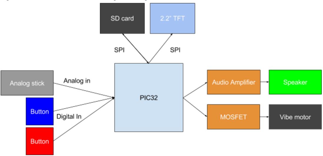
The high level design is shown below
The are 3 input devices with the analog stick, blue button and red button. We decided to use an analog stick as opposed to a directional pad with 4 directions because the games we intended to develop would greatly benefit from having an intuitive speed control. Pushing the analog stick further in any direction will produce varying effects. In most games, this is traditionally used to vary the speed of motion. The analog stick itself contains two 10K potentiometers, one for the X axis and another for the Y axis. Each potentiometer connects to the ADC, which scans over these pins and returns 10 bit value representing the voltage it receives.
The red and blue button, as well as the analog click button are all connected to GPIO pins with pull down resistors enabled. 2 buttons is fairly standard for gaming consoles, we felt that most games developed would struggle to find uses for more buttons than that. We did however include the joystick click button which can be activated by pushing down on the joystick. Although we did not use it for either of our games, we imagine that developers would find it useful, for example, holding down the button could increase speed of movement, which is a reasonable thing to have bundled together with an analog stick controlling direction of movement.
One of the biggest challenges in our design was determining how we could best utilize the SD card and TFT to develop a robust system. We came to a conclusion that drawing bitmaps from the SD card would not be fast enough given that we would need to use SPI to read the data from the card, then SPI again to write to the TFT. An alternative approach would have been to use an 8 bit parallel interface for the the TFT, but we would also have to have a separate SPI connection to the SD card and we would not have enough pins on the PIC32. Ultimately, with the number of pins we had on the PIC32, it was impossible to use a parallel TFT. We could have selected a different PIC32, but the significant extra development cost we would incur by not being able to use the 4760 libraries would pose a very difficult challenge. Ultimately what we decided to go with was to render all graphics with primitives in Tahmid’s TFT library, and offload all audio to the SD card. We can read data audio into a buffer on the fly when changing games, and thus allow various audio for each new game to be played without using our ROM. We can fit more actual game data into ROM now.
To immerse gamers in the experience, we used vibration motors to deliver rumble to the user during certain events. For example, in our games, if the player crashes into an asteroid or a hazard, the vibration motors will be triggered and the PICBOY32 will shake in their hands to indicate that they have been hit. The vibe motors are connected to a MOSFET, and we can use a digital output pin to the gate of the MOSFET to close the circuit and trigger the vibration.
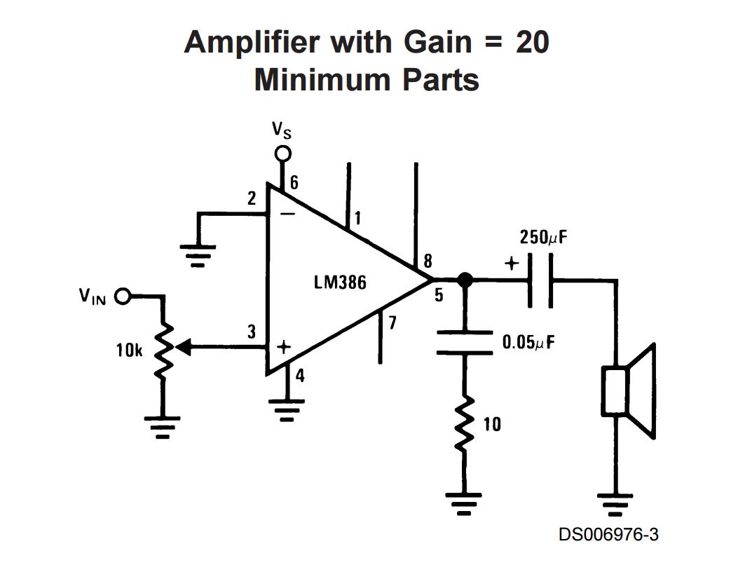
For audio, we use an 8Ohm speaker to deliver simple sound effects. We use the LM386 to amplify the audio for the speaker. We used a circuit from XiaoXing Zhao, Fred Kummer and Douglas Katz and their 4760 project, Laser Duel, to design the audio amplifier circuit.
Hardware
Our hardware design begins with a standalone PIC32 circuit. We used the design from Tahmid’s blog on standalone PICs, and Bruce Land’s standalone PIC lecture to design our circuit. We use the MCP1702 LDO to supply a steady 3.3V to the PIC. We power it with 6V from 4 AA batteries. The hardware for the input devices is simple. The analog stick only needs VDD and ground, and the output for each potentiometer connects to analog pins on the PIC. Each button is connected to Vdd and an internal pull down resistor in the PIC.
The vibration motors are connected to the 2SK4017 MOSFET. The gate goes to a digital pin. The voltage is supplied by the 6V input as opposed to the 3.3V to provide enough current to power the motors without interfering with the TFT. When we enable to pin, the MOSFET turns on allows to flow of current through the two motors.
The audio amplifier circuit is shown below. It comes from XiaoXing Zhao, Fred Kummer and Douglas Katz and their 4760 project, Laser Duel. The goal was only to get very simple short audio clips for various in game effects. This design uses very few components and was sufficient for our needs.
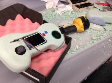
The TFT is connected as shown below to the PIC. It also includes 2 pins for the SD card, MISO and SDCS. MISO sends data from the SD card back to the PIC, and SDCS is the chip select for the SD card. CS is the chip select for the TFT, MOSI is the data from the PIC to the TFT or SD card, D/C tell whether the SPI message is data or command. RST is reset. In the appendix, there is a schematic for all of our circuitry. The following picture shows the PICBoy outside of its case earlier in development.
Game Case
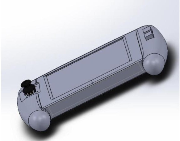
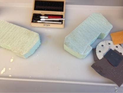
In order to design the case that houses our electronics, we employed a classic prototyping method called the foam method. This method involves shaping and carving a polyurethane block into the desired shape using a scalpel and sand paper. Polyurethane is a lightweight, stable and strong foam that can be easily cut and grinded. Polyurethane is outstanding for creating accurate and fine details. Therefore, the foam method happens to be a common prototyping method employed by industrial designers. We started with a 3D model, as shown below on the left, and extracted its top view, front view and side view. By using a printed copy of model’s three views, we could carve out the desired 3D design. The image below in the middle shows the carving process of our case leading to its final form.
Software
Reading Inputs
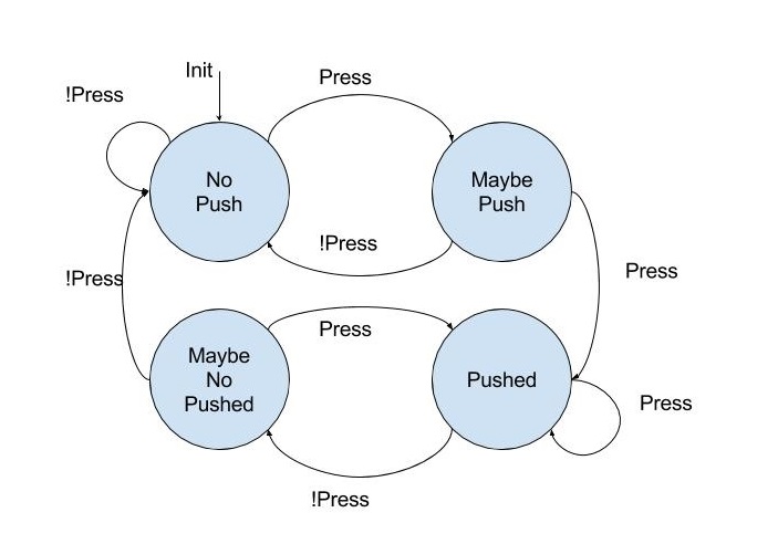
We have a single thread that runs every 10ms and polls all the input devices. This reads the ADC for the analog stick and debounces the buttons. We use a state machine to determine whether a button has been pressed and to limit button button presses on a per game basis. The ADC is 10 bit and thus we can see values from 0 to 1024. The joystick worked by using two potentiometers, one for each axis. It would center at around 500 and would vary between the minimum and maximum when pressed fully to its sides.
All of our input functionality is abstracted out to a separate file in order to remove too much hardware interfacing for the game programmer. Upon starting up the PICBoy, the calibrate_joystick function is called, which sets variables that refer to the steady unmoved state of the joystick. This is to determine whether the joystick has been moved in either the horizontal or vertical direction. Another function in our input library is to interpret the joystick movements and translate them into movements that the game developer can use. For instance if the joystick is pushed up, depending on how far it is pushed, it can return a value from 1 to 3. It will return negative numbers for downward presses (-3 to -1) and 0 for no movement. It uses the difference of the current joystick ADC value and the calibrated value to determine this difference. We also have several functions to check if a button is pressed and advance the state machine. Every time the function is called by the thread, it will advance in the state machine as shown below. This allows us to detect a single button press.
Launcher Thread
This thread is used to select which game you want to play. It displays a list of games available, and using the analog stick, you can move the cursor to which game you would like to play. Pressing the blue button will select the game and launch it. This thread will then loop through all of the game’s threads to schedule them. There is a game_over flag that is set once the game ends, and that signals that the launcher should exit the scheduler and return to the launcher. Pressing A on the game over screen will reset the launcher back to the start. The following FSM shows this process.
SD Card
The micro SD card was held in a holder connected to our TFT LCD screen. As the two are on the same board, they had to share the same SPI line, but use a different chip select. In order to get it to work, we used the Microchip filesystem library and code provided by Tahmid Mahbub. His code made use of the Microchip libraries and documented which hardware configurations needed to be changed in order to work with his setup. We then found that we needed to make similar changes, such as using the SPI2 configuration rather than the SPI1 that he used. In addition, we needed to set pins in the library for SPIIN, SPICLOCK, SPIOUT, and SDCS. When the file system is initialized, it also sets up the correct SPI outputs, and we needed to set the register there as well. Since we were using SPI2 and pin 9 (RA2), we would set SDI2R to 0, as that was what was required by the PPS output. We would also need to set the SPI output, using RPB11R, as we were using pin 22. This setup the hardware to actually use SPI2 and which pins to expect input from the SDCard, and where to output data.
Unfortunately, there were some challenges that arose when doing this setup. We found that even after setting up the hardware correctly, we were unable to initialize the file system library. After a lot of debugging we found that if we used Matt Filipek’s project structure but used our own code, we were able to read from the SD card. In addition, we found a bug with the TFT library, where if we had used the yellow text color before reading from the SD card, we were unable to view any files on the card. Changing this to a color like white fixed this problem.
The purpose of the SD card was to store sound files in a .wav format to use in our game, as the PIC would not have enough space to hold multiple sounds. While we can load the data into memory as needed, we needed more information to setup the interrupts based on their sample rate. In order to determine this, we used the header of the wav file. Tahmid provided a function that would extract this information from the header and we could then use it to open Timer2 with the correct frequency. Thus we could then read the SD card and bring in the sounds into our buffers and then start up DMA to play these sounds, using the timer to interrupt and send the sounds to the VREF DAC. The VREF DAC after being set up, can directly send the digital data we read from the wave file as an analog signal that we can play from the speakers. In order to configure the DAC correctly, the data needs to be 4 bits and it needs to be ORed with 0x8060 as the top 28 bits configure the DAC.
We use two DMA channels to output sounds and have two large buffers allocated to hold the sounds for games. Either buffer or both can be filled upon the user choosing a game, and after that initial setup, the SD card does not need to be read again. We do this because we wanted to use DMA to output the sound and since the TFT and SD card shared the same SPI line, we could see some lag in updating the screen for our game.
Asteroids
We made an asteroid game where the player controls a ship and asteroids fly across the screen. The player can rotate the ship using the left and right controls on the joystick and can move forward in the direction the ship is facing by pressing the joystick up. Whenever an asteroid collides with the ship, the player loses a life. When the player runs out of lives, the game ends. The ship also has the ability to shoot at the asteroids, and each time the A button is pressed a bullet it shot out of the front of the ship and moves in the direction the ship is facing. When one of the bullets hits an asteroid the asteroid is destroyed and the player’s score increases by one. The objective is to reach as high a score as possible before losing all of one’s lives. In addition, each time the player is hit by an asteroid, the PICBoy will vibrate giving the player haptic feedback for the death. Each time an asteroid is destroyed a sound will play through the speakers. This sound can be customized using the SD card.
Most of the game relies on two threads, with an additional thread used for printing the score and lives. One thread focuses on drawing the asteroids while the other focuses on the user-controlled ship. The asteroid thread computes the new position of each asteroid and bullet and determines whether there was a collision between asteroid and bullet or asteroid and ship. It does this by using the speed of the two entities it is checking as well as the current positions, thus determining whether the collision has occurred or will occur before the next redraw. We have this thread running faster than the thread that controls the ship because we found that if the control thread was too fast it would be a lot harder to control the ship. That thread needs to determine which direction, if any, the joystick is tilted in and whether a button has been pressed. If a button has been pressed, it prepares a bullet to be shot the next time the draw_bullets function is called by the other thread. This way we isolate user input and the movement of other objects on screen.
Upon starting the game, the asteroid, ship, and bullet structures are initialized. They take up a constant amount of memory and their fields are modified as they become used. For instance, there is an active field so if an asteroid is destroyed it will not be drawn again at the same place it was destroyed at and will need to be reinitialized. The same concept applies to bullets. Other fields include speed, position, and color. Most of these are randomized with some constraints so that the game is always different.
In order to have our ship (a triangle) rotate we needed to use rotation matrices to translate each point of the triangle to its new position upon pressing the joystick left or right. We knew it would be computationally intensive to compute sines and cosines as needed every time we would rotate the ship, so we decided to have a sine table in our code and a field in the ship struct. Thus, each time the ship was rotated by the user, we would change its rotation variable by 1 mod the size of the sin table. We also wrote small macros for finding sin and cos given a rotation, where cos was just a lookup into the sine table with an offset. Thus, we could simply do a few lookups into the sin table and a few multiplications and additions to find the new position. We found this to work quite well and the resolution of each rotation was determined by the number of entries into the sine table. Had we added more entries, the rotation of the ship would be more fine tuned.
The following video shows gameplay
PICRacing32
The rules to this game are simple. The player drives a car on a straight road, and the road is always moving beneath them at at least a fixed speed. Hazards on the road approach the player and they can move in all directions to avoid them. The A button accelerates the car, thus making hazards come faster, and the B button slows the car. The car naturally slows down at a slower rate than braking, but in order to effectively navigate hazards, it becomes necessary to brake. Each second that passes by, the score increases based on the player’s speed. As time goes on, hazards will spawn more often. Hazards also pile up faster at slower speeds. It is to the player’s advantage to accelerate when possible, and slow down when hazards approach.
The game consists of 2 main game threads, and a scoring timer thread. The first thread draws the track and the moving centerline which gives the illusion of upward motion. There are five lines that are drawn with a fixed separation, and their starting position is incremented by the speed of the car, then wrapped around when it reaches the end. The second thread draws the hazards and moves the car. Each frame, the car is moved based on the readings from the ADC, and then its speed is increased or decreased depending on which buttons are being pressed. There is a counter that is set for how long before a hazard should spawn. Every frame it is decremented and when it reaches 0 it is reset. The value it is reset is to is determined by the amount of time that has passed in the game. The longer the game, the faster the spawn. Each hazard can spawn in 1 of 6 imaginary lanes randomly. When a hazard is spawned at the top of the screen, it moves down the screen at a speed equal to the speed of the car. If it reaches the bottom of the screen, that hazard is deactivated. Every frame, each hazard is checked for whether it is currently colliding with the car. If there is a collision, the number of lives is decremented, and a rumble is triggered for five frames. We can use the same functions as Asteroids to animate the hazards and check them for collisions with the car. The car has the same animations as the ship, it just uses a different sprite. The scoring thread is run every 20ms and keeps track of how much time has elapsed and records the score. It then prints these values onto the corner of the screen. Every time the car accelerates, an accelerating sound effect is played, and every the car brakes, a screeching sound is played. These sounds are brought in from the SD card when the game is launched, and then DMA to the DAC when the events are triggered. When all the lives are run out, a game over screen is displayed along with the current high score for the game. The code can be found in the appendix.
The following video illusionstrates the game play.
Results
Our design was quite successful in accomplishing what we set out to do. The controls are tight and the frame rate is smooth. PICRracer32 runs at 60 frames per second on the PICBoy, and asteroids runs at 30 frames per second, but could go even higher. The speed was tuned to that frame rate, and we did not yet parametrize it based on frame rate, and so the game became very difficult to play at high frame rates. We were able to successfully play multiple sounds on the fly for either game. The sound quality is not great because we are only using 4 bit audio and a very simple audio amplifier. There is a slight whine in the audio, but tuning the trim pot on the amplifier is effective in removing the whine, while still producing a good sound volume. When we put the PIC into the case, we began to see some glitches in the analog stick. We believe that it may be the result of some analog interference caused by long wires from the stick to the PIC. It was too late at that point, but ideally we should have positioned the analog stick much closer to the pick to reduce interference caused by the long wires and surrounding noise. The case is a bit bulky and someone with smaller hands may have trouble reaching all the buttons. Had we printed a PCB and 3D printed the case, we may have been able to shave it down a little to increase its usability. Below is our video demo of our project.
Demo
Conclusions
Possible Improvements
There are certain aspects of the project we would definitely like to improve upon. For instance, we could definitely use better memory management in our code to possibly make space to bring in longer sounds or even enough space to hold the data for another game (given that there is enough program memory as well). In addition, we made our enclosure out of foam and to have a better feel we could possibly 3D print the design. The SD card allows us to store a lot of information as well, and we could use it to store high scores. We attempted this while making the project but were unable to figure it out in time. Using this we could then add a feature to input a player’s name and save their high score to the SD Card and keep track of the top scores. There is also room for improvement on the games, such as making hitboxes tighter and adding special bosses that appear after a certain score, to make the game harder.
Intellectual Property Considerations
The hardware designs we used have been properly cited as well as the software we used. We used code provided by Tahmid Mahbub on his blog, which we have referenced as well as the project settings from Matt Filipek’s Smart Watch project, which were needed for our SD card. We also cited the amplifier diagram from Xiaoxing Xiao, Fred Kummer, and Douglas Katz’s Lazer Duel project.
Ethical/Legal Considerations
We made sure to follow IEEE Code of Ethics while making the project. We properly cited any resources we used and did not discriminate based on race, religion, gender, disability, or any other factors. We made sure that no one will be hurt by using our game system as all soldered components are hidden away, except for the power switch. In a final casing this would also be inside the casing. When soldering we made sure to use the proper safety equipment. We also clearly stated what works and what does not work with our project, and were honest about it. Our game system is based off of the game systems we have used such as Nintendo’s Game Boy. We also based our Asteroids game off of Atari’s game of the same name. We feel that the design is generic enough that it does not pose any legal issues with Nintendo or Atari.
Appendix
The group approves this report for inclusion on the course website.
The group approves the video for inclusion on the course youtube channel
Gaurab: Designed and built hardware, wrote software for racing game, debugged software and hardware
Gautam: Wrote software for inputs, asteroids game, integrated SD card, and debugged hardware
Apoorva: Designed and built enclosure for circuitry