Conclusions
Through the ECE 4760 design project we were able to explore the domain of wireless communication modules like the Bluetooth, sensors etc. and their integration with the pic32 microcontroller. There exists an incredible amount of scope to expand upon this project. Some of future improvements we would like to make include designing of an autonomous parking mode and an intelligent path planning algorithm for the robot. Our design with the sensors can be improved through the utilization of their values to intelligently train the robot to perform specified tasks. Initially we also proposed to have an alternate energy source for the car. We planned to have a saline water based power source where the car runs on the voltage obtained through the electrolysis of salt water. Due to time constraints and infeasibility of the technique at this stage we had to stick to the 9v battery to power the car.
Intellectual Property Considerations
We appreciate the work by Adam Dunkels in developing Protothreads for C and our Professor Bruce Land who provided us with an extended version. Protothreads were extensively used in our project. Lastly, we appreciate the example set by Shaan Shetty, Alberto Gutierrez and Boling Hu in their ECE 4760 Final Project in 2016; although their project was somewhat different than ours, they did provide us a clarity on the approach that we were thinking for our project. We also want to acknowledge Samir Durwasula, Justin Selig and Adarsh Jayakumar for the work done on the website for their final project report in 2015. Ideas were taken from their report to create this website. We have acknowledged all use of code and have abided by all copyright statements on both code and hardware. We have given credit to all hardware devices that were used in this project, as well as the code that was referenced in our final program.
Ethical Considerations
In Accordance with the IEEE code of ethics, we considered our design choices carefully and we held ourselves to high ethical standards which included working to not only ensure our project met all quality technical standards, but also holding ourselves to a professional working standard. Our device was made by ensuring that nobody will be harmed during use. Our project is absent of any potential unsafe factors which intentionally endanger the public or environment. We made no claims that the device can do something it cannot, nor is something that it is not. As we have open sourced our designs, we have minimized any potential conflicts of interest and false claims about the technology used. We hope that our documentation can help others better understand the technology behind microcontroller design, and we welcome any honest criticism and feedback readers may have upon us. By designing this obstacle avoidance car, we intend to make an autonomous accident free car on which most of the big companies like Tesla and BMW are working on. As such, we've strove to make as great an impact on this market as possible given the time constraints and available resources.
Legal Considerations
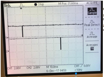
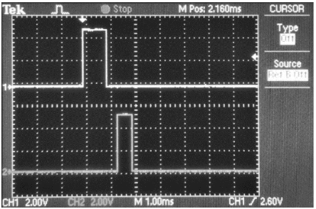
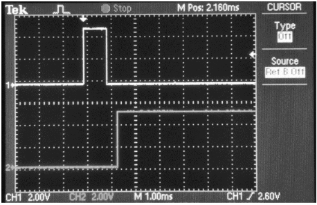
Our project includes a Bluetooth Module and Ultrasonic sensors. Our HC-05 Bluetooth module uses the Bluetooth specification v2.0+EDR protocol, operates on a 2.4GHz ISM band, and has an emission power of <=-84dBm. It also operates at 3.3V and includes authentication and encryption protocols for data transfer. Pulse transmissions for the Ultrasonic sensors HC-SR04 were brief and in the inaudible 40KHz frequency. Use of the car chassis and lab equipment was fully authorized, with prior permission from the lab staff. These components and respective specifications adhere to FCC standard restrictions and thus our design is capable of operating legally in the US.
Acknowledgements
We would like to give a special thanks to our professor Dr. Bruce Land for all the recommendations, support and guidance that he provided to us throughout our work on this project. Prof. Land was of immense help in getting this project completed. We would also like to thank him for building a great course from which we have gained enourmous amount of knowledge and hands on experience. Also, we would like to thank the TA’s especially Samir who was our lab TA, for the continuous support and guidance throughout the semester.
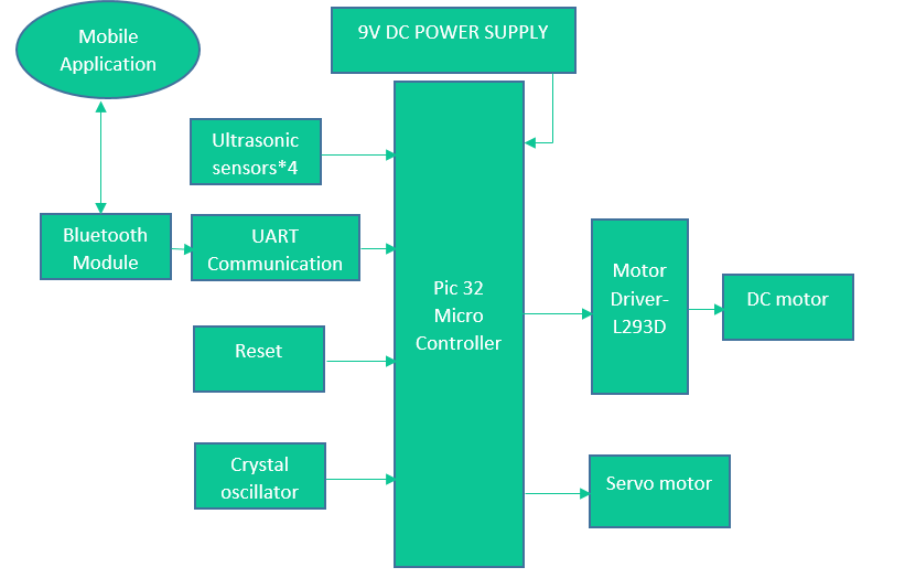 Figure 1: Block Diagram
 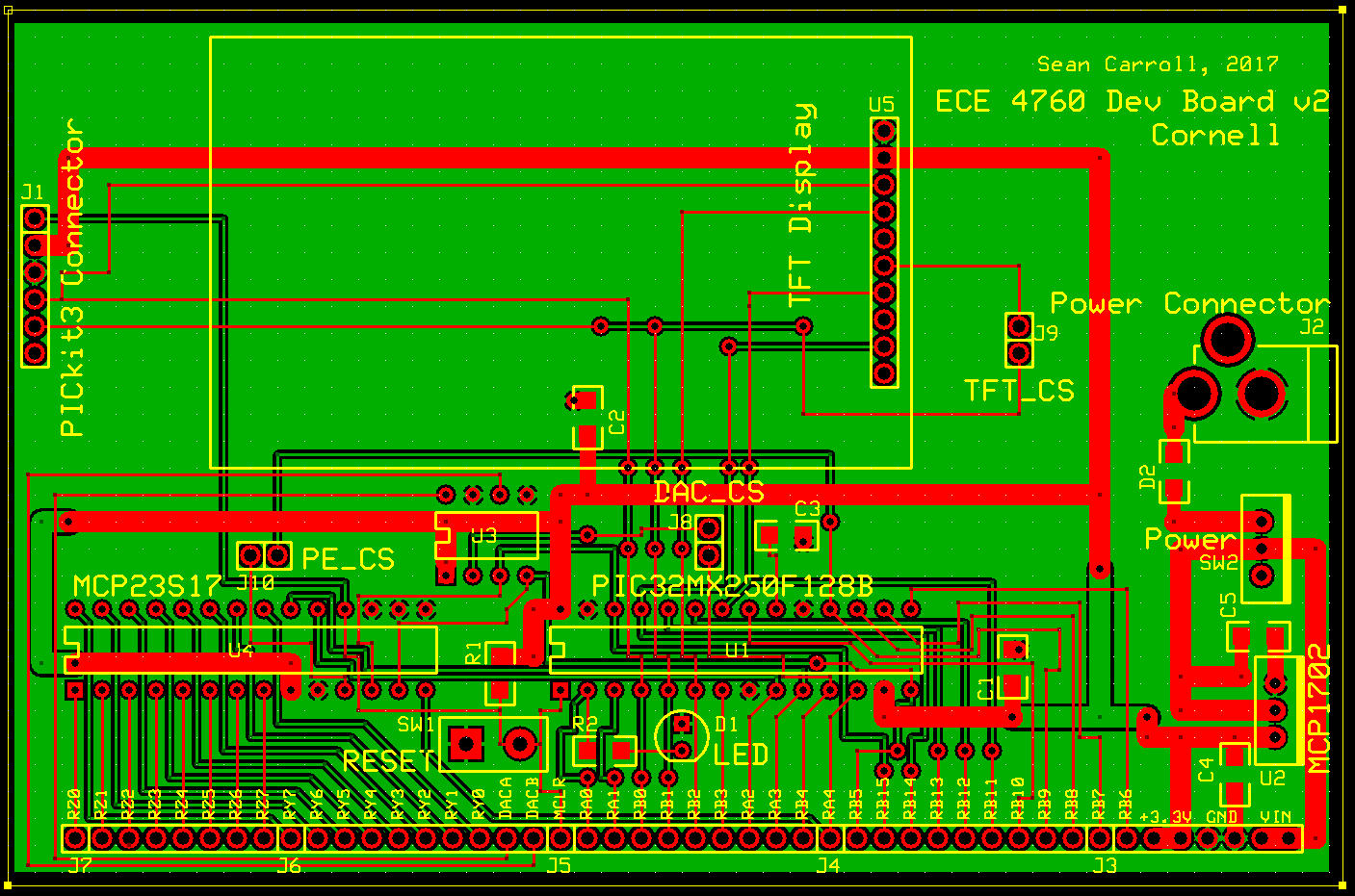 Figure 2: PIC32 Layout
 Figure 3: HC-05 Bluetooth Module
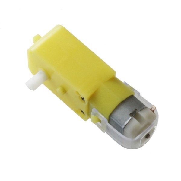 Figure 4: Dc Motor
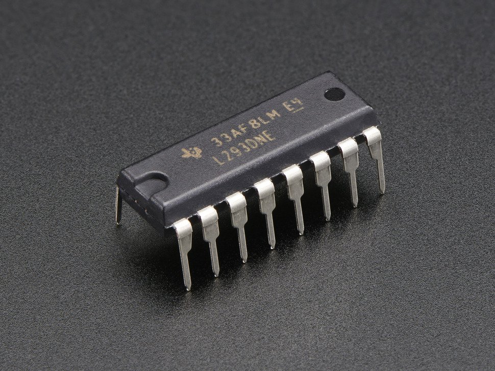 Figure 5: Motor Driver
 Figure 6: 4N35 Optoisolater
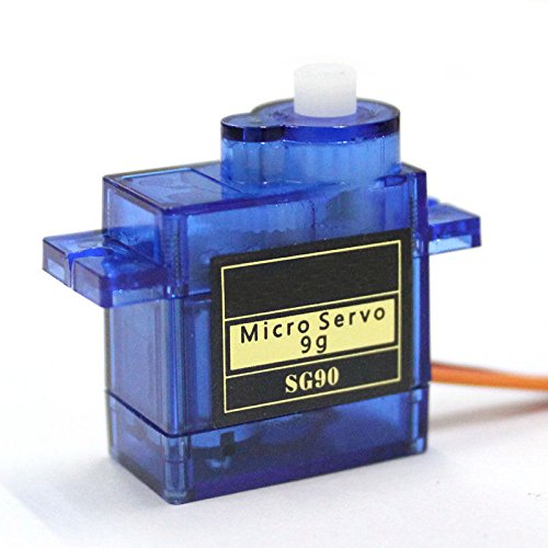 Figure 7: Servo Motor
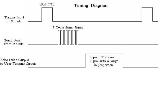
 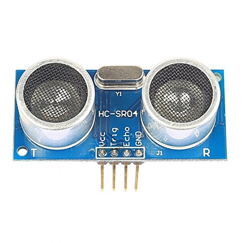 Figure 8: HC-SR04 Ultrasonic Sensor
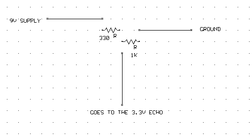 Figure 9: Voltage Divider
 Figure 10: Car Chassis
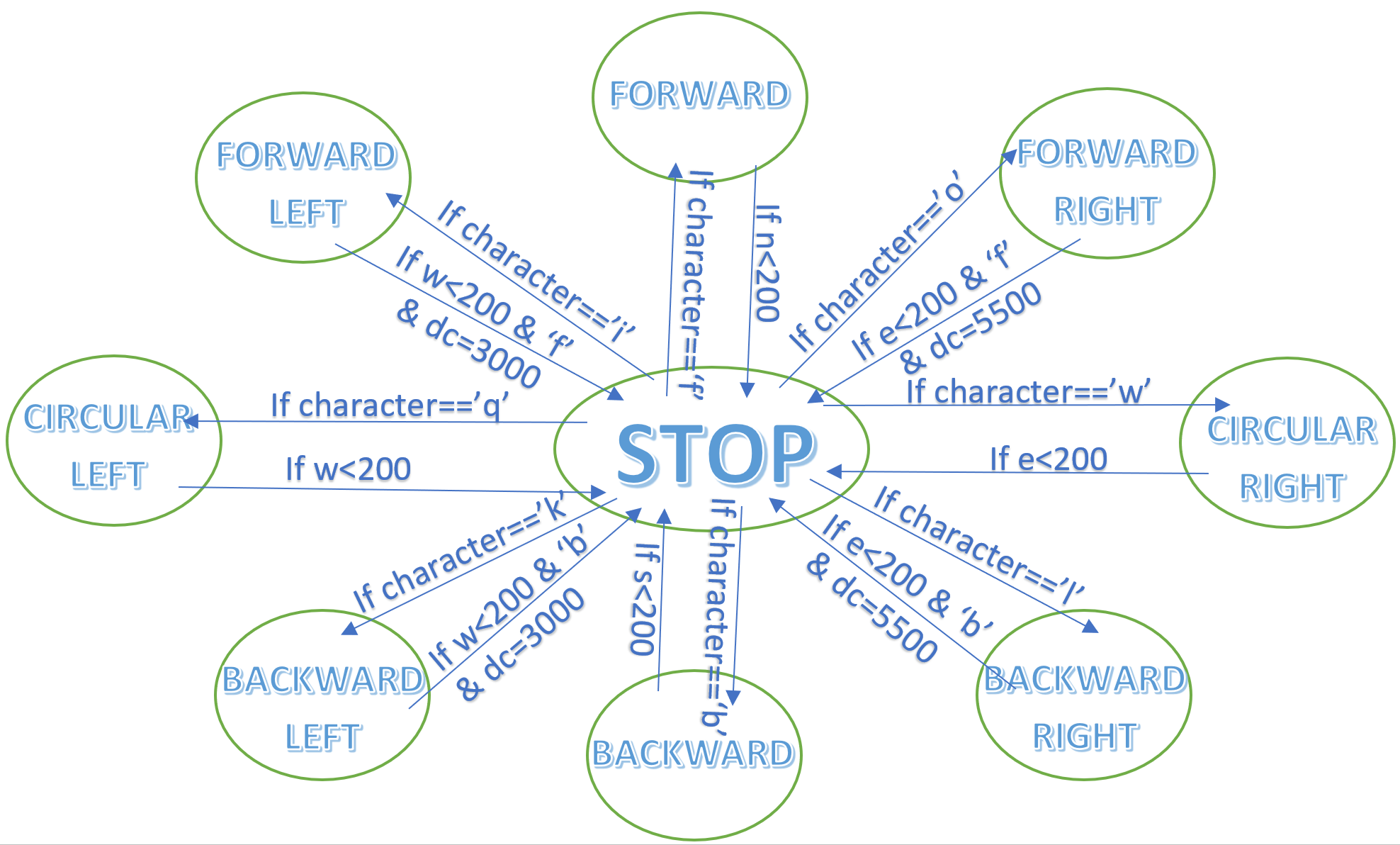 Figure 11 : Signaling Algorithm Functional Diagram