Final Report - VGA Video Game
Michael Henning (mch258) and Max Rademacher (mtr73)
Introduction
Do you ever find yourself lamenting that you live in a warehouse of unused VGA monitors, but don’t have any VGA signals to feed to them? Do you ever wish that you had a cheap way to drive these displays at high spatial and color resolution using a circuit you soldered with your bare hands? Do you dream, with with the entirety of your mind and soul, that you can crush bricks with a small ball and a paddle?
If you answered yes to any of the above questions, then the ECE 4760 VGA Video Game™ is for you! This amazing device drives a VGA monitor at 640x480 resolution at 60 Hertz with 64 distinct colors, using only a single PIC32 microcontroller and a small amount of external electronics. If that isn’t enough, the device also comes with a full, playable implementation of a breakout-clone video game.
High Level Design
The goal of this project was to drive a VGA display just with the PIC32 and as little extra additional hardware as possible. This display should run at a resolution of 640 by 480 with a framerate of 60 hertz.
The VGA protocol can be found here. It consists of five signals: vsync, hsync, red, green, and blue. The vsync signal is a digital signal that pulses to inform the display to refresh and start rendering pixels at the top of the screen again. The hsync is also a digital signal and when it pulses, the display moves to the next line and starts rendering pixels from the left again. In combination, the frequency of these signals are used to determine the frequency of the pixel clock. For a 640 by 480 display running at 60Hz, the pixel clock will be running at 25.175MHz. This is the rate at which the display moves from pixel to pixel, updating each pixel’s color to the value represented on the red, green, and blue signals. These three signals are all analog, with zero volts representing none of that channel, and 0.7 volts representing all of that channel. When learning about the VGA protocol, we found this tutorial very helpful.
One of our goals was to have at least six bit color, which would give us a selection of 64 unique colors. Two bits are allocated to each color channel, and all six bits are outputted through the chip’s digital io pins. The two bits for each channel are then run through external hardware to convert the two digital signals into an analog signal.
It’s not possible to run the PIC at exactly 50MHz, so we found that we could drive the pixel clock at 24MHz and overclocked the PIC to 48MHz. This gives software two cycles per pixel. There is no way software could calculate the appropriate six bit value for each pixel and output that value in only two clock cycles. To alleviate some pressure off of software, we decided to use DMA for all of the data transfer and output. With this setup, software renders into a buffer while DMA transfers it to the output. Each color is stored in a byte, so DMA must transfer one byte per pixel.
Some problems arose when we found that the DMA could not run fast enough to transfer one byte every two cycles (one pixel clock cycle). The fastest DMA can transfer data is when it is unregulated by an external event. In this case, it transfers one byte every 4 to 6 cycles. This means not only that the horizontal resolution with this setup would be two to three pixels but also that it would be irregular. To make the transfer more regular, each DMA byte transfer can be triggered by an external event. We set up one of the internal timers to trigger the events but with this setup, the fastest the transfer speed can be run at is 10 cycles per transfer.
The PIC features two serial peripheral interfaces (SPIs) which send data over a single wire by serializing the bits that make up that data. They send one bit at a time, driving the wire high or low depending on the value of that bit. SPI can be configured to send this data at a rate of half the clock speed, which means the data can be transferred at 24MHz. So, with a single SPI the display can be driven at the desired 640 by 480 resolution, but with only one color bit.
The final design uses a combination of color data directly DMA’d to the output pins, while single bit brightness data (on/off) is DMA’d to an SPI buffer. The output of the SPI is then run through an external AND gate with each of the color bits. This solution allows us to have six bits of color, while maintaining the 640 by 480 resolution by “turning off” individual pixels. The drawbacks of this design, however, are that the background must be black and that two horizontally adjacent objects of different colors may see some color bleed. That is, two adjacent objects must be tha same color if they are in the same group of 16 horizontal pixels.
Hardware
The base of our design is the ECE 4760 small board, which is well-documented online. In addition to this base, we have added a few new hardware circuits.

Figure: Circuit for the red color channel.
The most complex of our custom circuitry is the VGA driver circuit, which is in charge of converting the SPI and 2-bit digital color signals from the PIC into analog color signals suitable for the VGA monitor. This occurs in three steps. First, all six bits of color are ANDed with the SPI channel, to produce a 6-bit output that is all zeros (black) when the SPI channel is off, and the value of the current color otherwise. Next, each color channel has its data fed through an R-2R resistor ladder to convert the two-bit digital signal into an analog signal. Finally, the three analog signals are fed through a voltage divider which brings the output voltage into the 0.7V range required by VGA for color channels. This output is then provided to the monitor.
We arrived at this design for the VGA driver board after multiple failed attempts. Originally, the plan was to feed the 2-bit color signals through the resistor ladder first to convert them to analog, and then use an analog mux to select between this analog color signal and ground using SPI. We thought this had a shot of working because the analog mux had a -3 dB point of 20 MHz, which we thought might be fast enough to switch for the ~25 MHz signals we were generating for VGA. We were wrong. The analog mux, even when multiplexing between Vdd and GND, completely mangled the high frequency signals we were generating with SPI. After wrestling with this problem a bit, and getting sidetracked trying out faster analog switches, we realized that we needed to swap the order of the MUX and the resistor ladders, so we could do the multiplexing on high frequency digital signals, which was much easier than working with high frequency analog signals. So, we ended up using 74LS08 AND gates at the beginning of our input, which could switch quickly enough for our purposes.
After the switch to AND gates, a simple one bit per channel color test circuit started working on our breadboard. Then, we introduced the resistor ladders to get the full two bits of color per channel. This circuit did not work. Up until that point, we had managed to route our ~25 MHz signals through the breadboard, despite our instructor’s warnings that such a feat was impossible. As soon as the resistor ladders were present, however, the circuit’s output became garbage. After some attempts at debugging, we finally decided that there was a decent chance the breadboard was introducing too much capacitance at too many different places in the more complicated circuit for the signals to pass through cleanly, and so we decided to try soldering the circuit without being able to test it. Luckily, the soldered circuit worked on the first try.

Figure: Joystick circuit.
The potentiometer and switch are part of the joystick unit.
The input device for controlling our game is an analog 2-axis thumb joystick from Adafruit. The Y-axis of the joystick is connected to B13 of the small board, where it is fed into the ADC on the PIC. The button of the joystick, which connects SEL to ground, is connected to a pull-up resistor. The active-low signal for the button is then connected to RA2 on the small board.

Figure: LED Circuit
In addition to the hardware mentioned above, we also included an LED, connected to RA0, which is used for debugging purposes.
Software
VGA Driver Logic
The first thing software does is setup the internal hardware for the vsync and hsync pulses. After setup, however, the pulses are generated entirely in hardware to ensure precise timing and to free software to do other things. The timing of each pulse is managed by a timer, whose value is fed into an output compare unit. The output compare unit is configured to output a high signal while the timer value is below a certain threshold and low otherwise. With the timer period and output compare threshold for each signal set to the appropriate values, the two sync signals can be generated accurately.
There are two separate render buffers for the pixel data: a color buffer and a pixel state (on/off) buffer. Both of these are double buffered to allow DMA to transfer the current line, while software renders into the next line. This means that each buffer is twice the size it would need to be to store data for a single horizontal line. DMA transfers one half of the buffer, while software renders into the other. After each hsync pulse, they switch.
After setup, all of the software logic is implemented in interrupts. This is because the timing of everything in software for this project must be very precise. The double buffering logic is managed in an interrupt which is fired at the beginning of every hsync pulse. Once the DMA transfer has started, that interrupt calls the render function to render the next line. The game logic is implemented in an interrupt which fires every vsync pulse.
Game Specific Logic
The game we chose to show off the driver’s capabilities was breakout. This game is simple enough to implement in a few days but allows us to show off the resolution with a circular, moving ball and moving paddle. It also allows us to demonstrate the range of color selection by coloring each brick differently.
In our implementation of the game, the player controls the velocity of a paddle on the bottom of the screen to try to bounce a ball and hit bricks. When the ball hits a brick, it bounces off and the brick is destroyed. Once all the bricks are destroyed, the player wins. If the ball falls off the bottom of the screen, the player loses a life. When there are no remaining lives, the player loses. Each time the paddle and ball collide, the ball speeds up to increase the difficulty of the game.
The ball has an x, y location and and x, y velocity. Each frame, the game updates the ball position according to its velocity and then the game checks for a collision. The simplest collision checks are with the edges of the game space - each of the coordinates are checked individually to see if they are outside of the predefined bounds. The paddle collision is similar; the ball must be over the paddle in terms of the x axis, and intersecting the paddle on the y axis. All surfaces in the game are either vertical or horizontal, so once a collision for the ball has been detected, the collision resolution is fairly simple. If the ball collided with a vertical surface, the x velocity of the ball is negated; if it collided with a horizontal surface, the y velocity of the ball is negated.
The paddle also has a variable position and velocity, but these are only in the x direction. To determine the velocity of the paddle for the frame, the game reads in the value of the ADC and scales it to the range of allowable paddle velocities. Then the game updates the paddle position with its velocity.
The bricks are stored as an array of bytes representing the colors of the bricks. If the color is black, the brick is considered destroyed. With a constant dictating the number of bricks per row, the array can be considered a grid. To detect ball-brick collisions, the game determines the bounding box of the ball and loops over all the bricks that fall in that box. If the brick exists (i.e. its color is not black) a collision with that brick is evaluated and the brick is destroyed (its color is set to black).
Because of the design of the VGA driver software, the game must be rendered one line at a time in order. So, the render function first checks which y value it is rendering and determines its behavior based on that. If the y value lines up with a row of bricks, the function iterates through the bricks in that row, setting the color values to the color of the brick and setting the pixel state values based on the brick width constant. It sets all the pixels under a non-destroyed brick to on, and the rest off. If the y value lines up with the paddle, the function sets the appropriate section of the color buffer to the color of the paddle. Then it sets all of the pixels under the paddle to on. Finialy, if the y value lines up with the ball, the function sets the appropriate section of the color buffer to the color of the ball. To get the circle shape, a line of pixels are set to on, where the line is centered on the ball x location and the size of the line is looked up from a precomputed array of lengths. That array is indexed into based on the relative y location.
Text Rendering
Rendering text was a subgoal of this project and important for the game. We downloaded a public domain bitmap font and added it to our project. The font is stored as an array which is indexable by character and then by y value. To render the text, we iterate over the characters, setting the appropriate bits on and off.
Text rendering was where we noticed some of the limitations of our engine. The rendering took too long and DMA began to get ahead of the rendering which made everything look corrupted. We realize that we had very limited rendering time so we implemented logic to turn on the LED if we ever ran over on rendering time. Then we optimized our rendering logic until the LED did not turn on.
Results
The video of us demoing this project can be found here: https://youtu.be/cgSOXxtIgHo.
We met most of our goals and came quite close to meeting the ones that we missed. Our system was able to output six bit color to generate 64 unique colors. We were able to drive the display at 640 by 480 monochrome pixels. The horizontal color resolution, however, was less than this due to limitations in DMA speed. Clocking in at 57Hz, we almost met the goal of a 60Hz refresh rate. While the image displayed on the screen is steady and animation is smooth, there is a slight jitter in the display that occurs about once every five seconds.
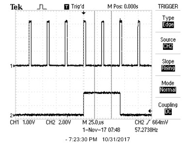
The above image is an early oscilloscope trace of the vsync (top) and hsync (bottom) signals generated from the timer and output compare units. Because we the closest we could get the pixel clock to 25MHz was 24MHz, the vsync signal ran at about 57Hz instead of the intended 60Hz. However, we quickly found that the monitors we tested on had no problem displaying at this frequency.
This is a screenshot of an oscilloscope trace showing the hsync signal (top) and a one bit color signal (botton). All the color signals must be zero volts during either a vsync pulse or an hsync pulse. The color signal shown here was quickly hacked together in code, so its duration was liable to vary.
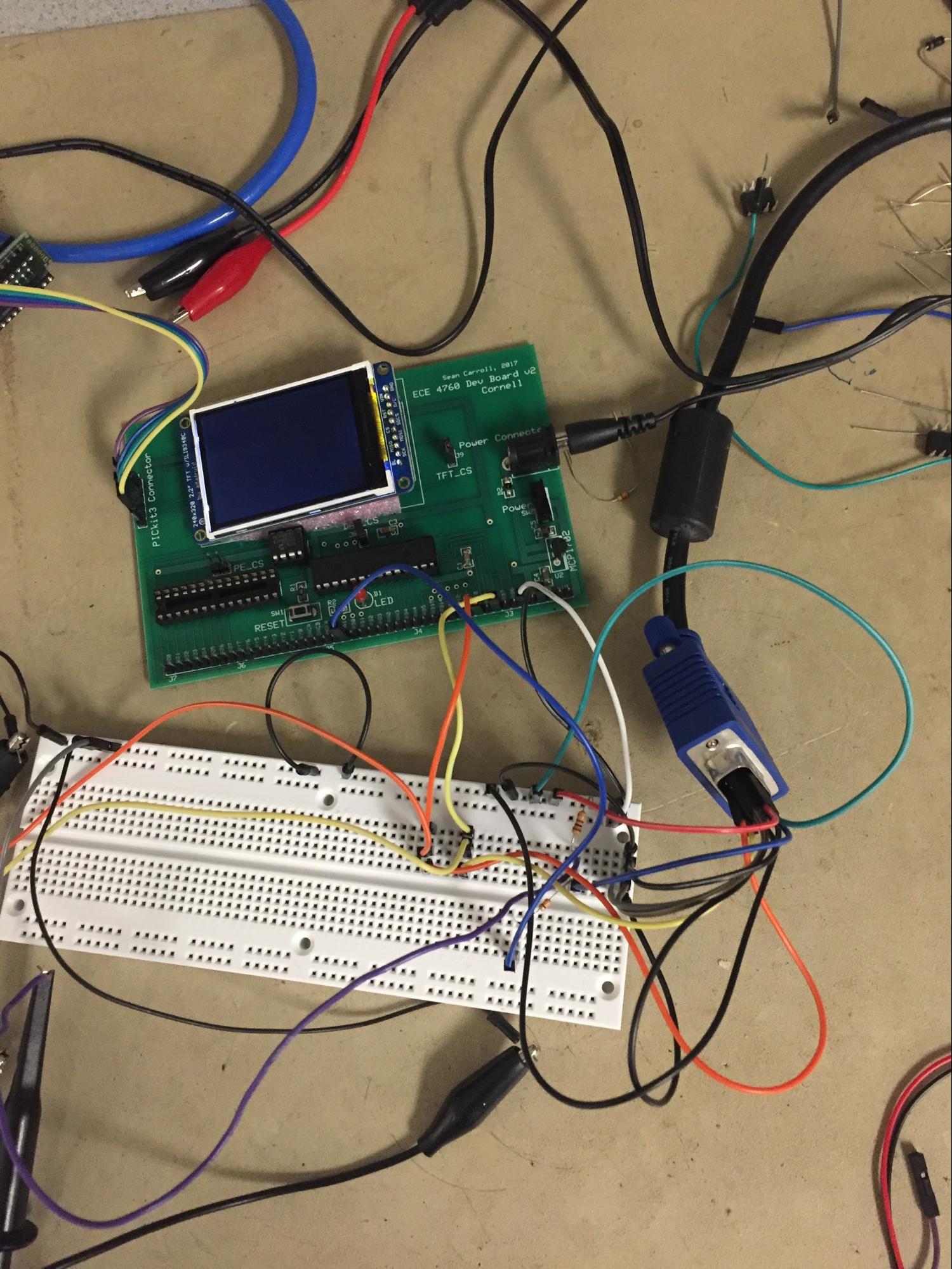
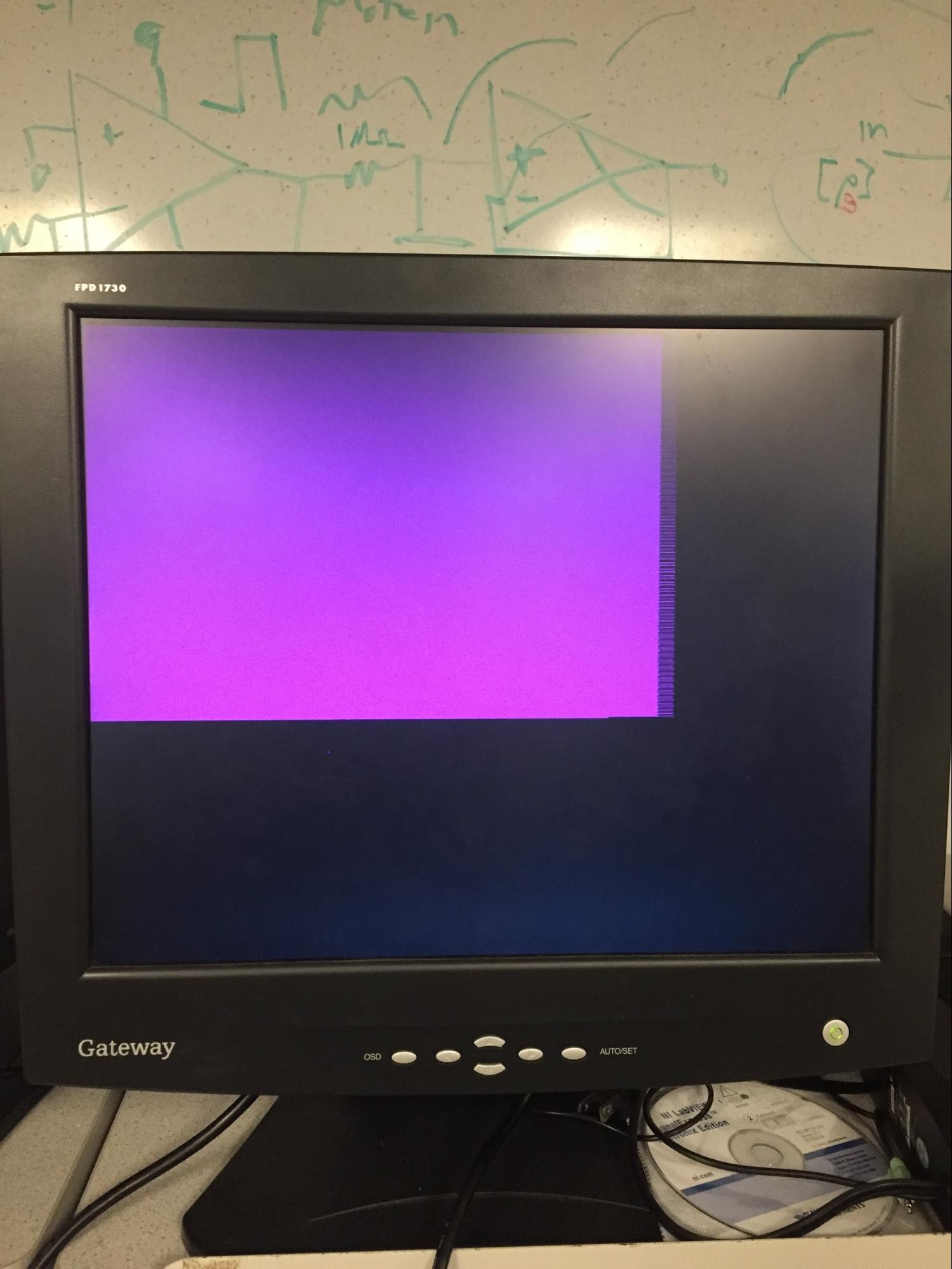
We wired the PIC to the VGA cable as shown on the left. The red and blue channels were wired to the color signal and the green channel was wired to ground. This generated the nice purple rectangle displayed on the monitor in the image on the right. The zagged edge on the right of the rectangle is due to poor timing in the color signal logic. We intentionally cut off the signal earlier than the right and bottom edges of the screen to ensure that we were turning off the signal correctly.
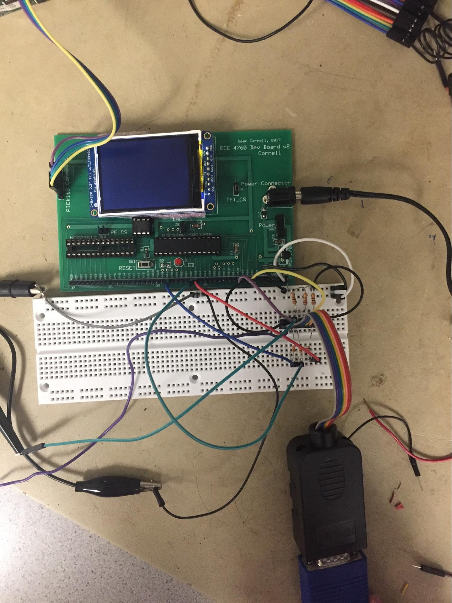
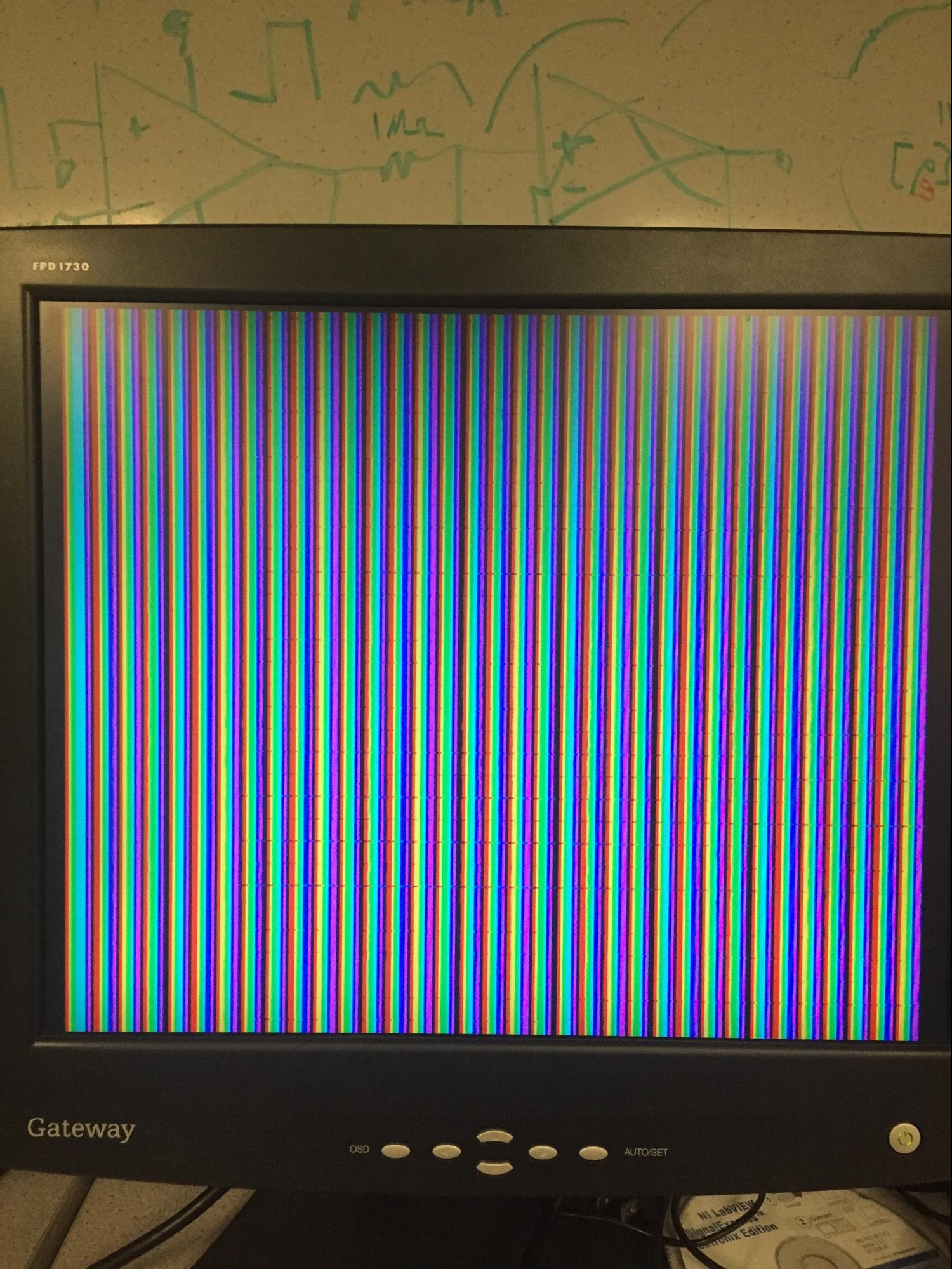
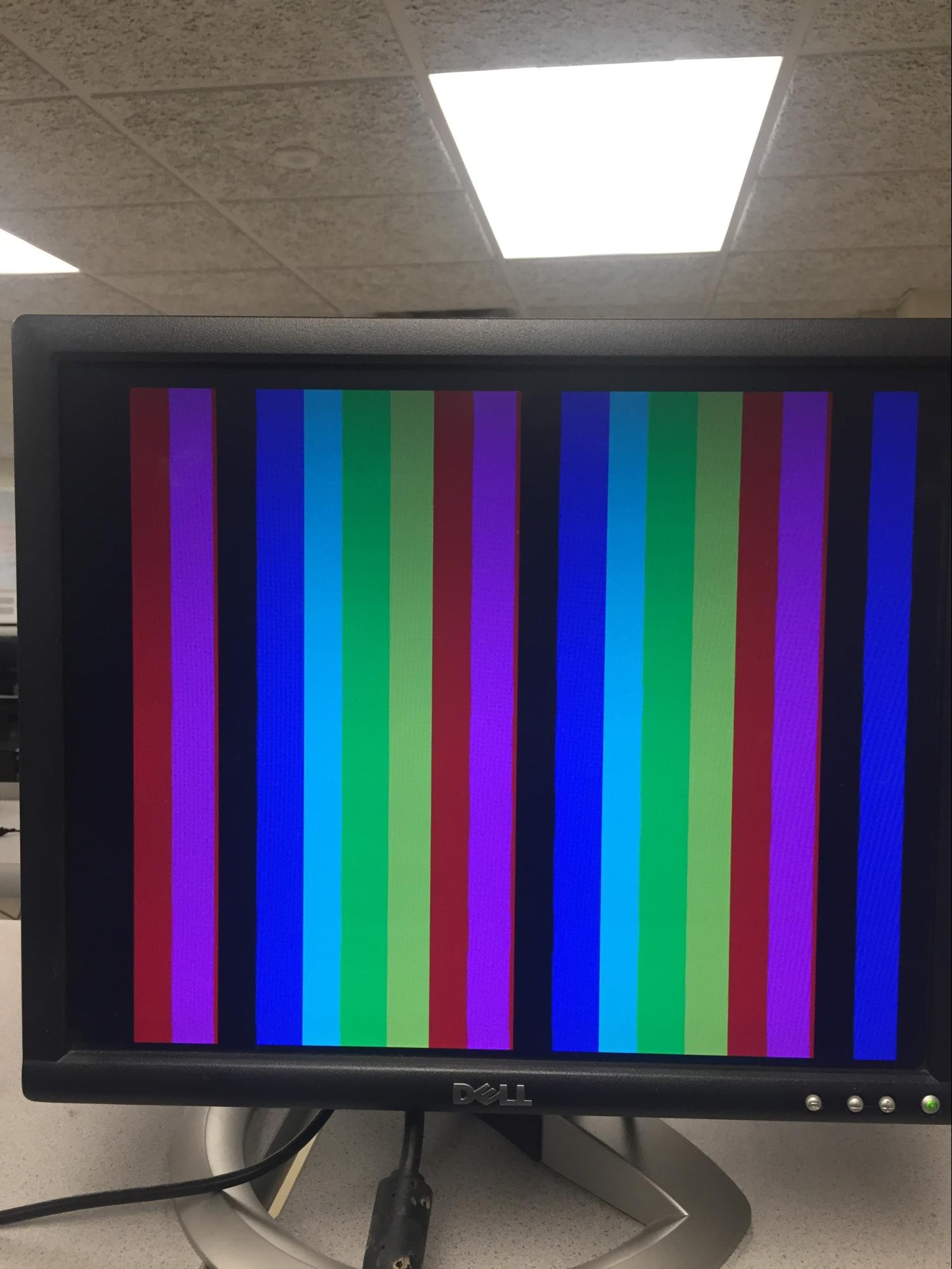
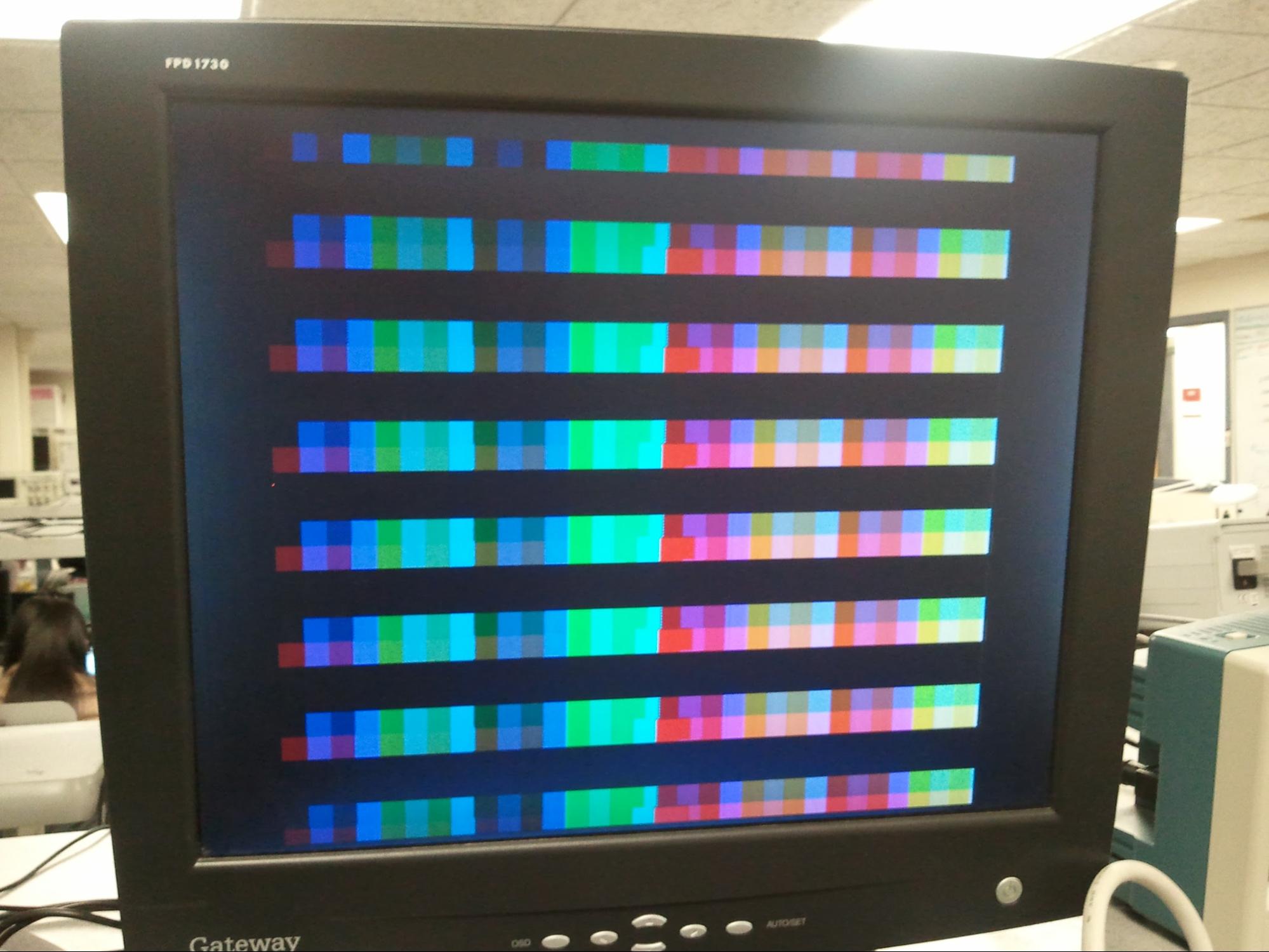
The image on the left shows cleaner wiring because we got the VGA breakout board. We wired up all of the color channels to separate output pins and setup DMA to transfer a rainbow color pattern as fast as possible. This generated the picture shown on the display on the right. Note that each stripe is wider than one pixel. This is how we realized we needed a different solution than DMA by itself.
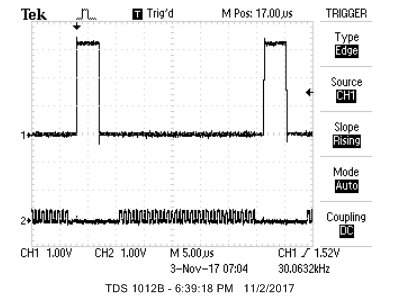
This image shows an hsync signal (top) and a one bit color signal (bottom). The color signal is being driven by SPI which was transferring a buffer filled with one repeated byte: 0xAA. That is an alternating pattern of on, off, on, off, etc. We did this to see if the SPI alone could drive the color values at the necessary frequency of 24MHz for the desired resolution of 640 pixels per line.
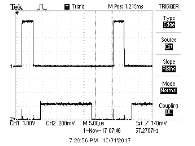
Above is an early test of running two DMAs at once: one to the color output and one to the SPI. The color output was wired to drive the red and green channels, while the SPI was wired to drive the blue channel. This illustrates that both can be run simultaneously but it also shows that the two DMA transfers are not aligned. On a closer look, one can see that the SPI signal is a few pixels ahead of the color signal. The offset is easily dealt with by adding however many pixels necessary to the index of the pixel state buffer. However, the size of the offset varies as the program and render logic change. Unfortunately we were not able to come up with a general case solution, so we just tweaked the offset in our final product.
For some of our first attempts at combining the SPI signal with the color signals, we tried an analog mux and analog switch. The idea with each was to immediately run the color output through the resistor ladder to generate the analog signal before combining it with the SPI signal. Both options were shown to be infeasible as they highly corrupted the signal even at very low relative frequencies.
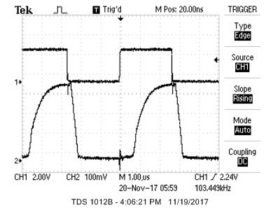
For the mux, we wired the SPI signal (top) to control the select bit of the mux. The two inputs of the mux were wired to high and low such that the whole system should’ve operated as the identity function. The output signal of the mux is displayed on the bottom. Even at the extremely low frequency of 103kHz, the output signal of the mux was still highly distorted.
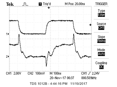
For the switch, we wired the SPI signal (top) to control the switch. The input of the switch was wired high and the output of the switch (bottom) was attached to a pull-down resistor to keep it from floating. Just as with the mux, this system should’ve operated as the identity function. However, even at very low frequencies the output signal was extremely distorted.
The final solution of digital AND gates before the resistor ladder with each of the six color bits resulted in minimal distortion even when running a signal through at 24MHz.
An image displaying the 64 different possible colors
The game turned out well and plays smoothly. Below are some screenshots of the game in action.
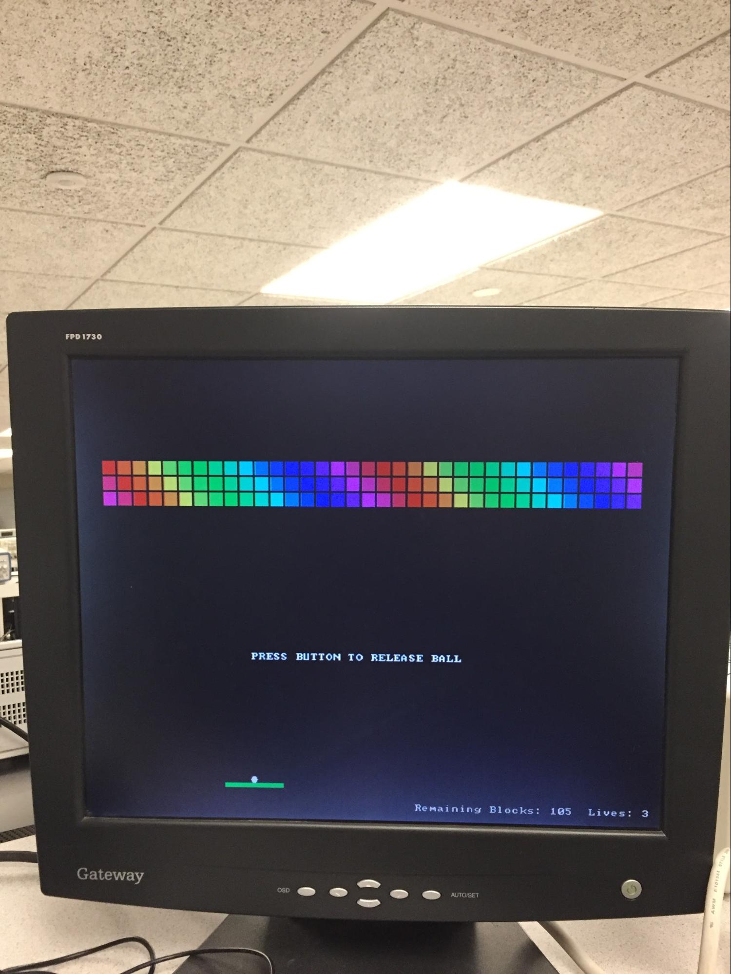
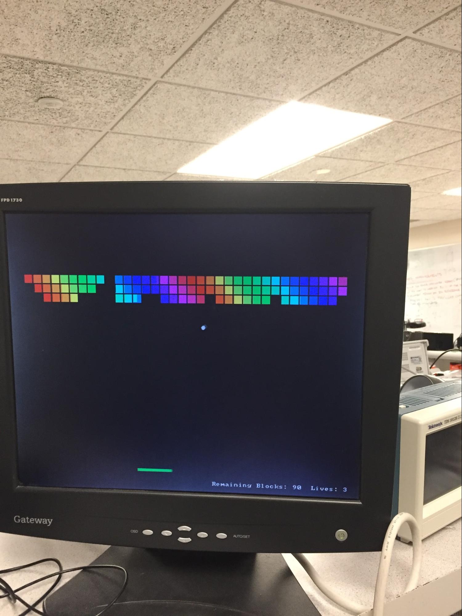
Start screen In game action shot
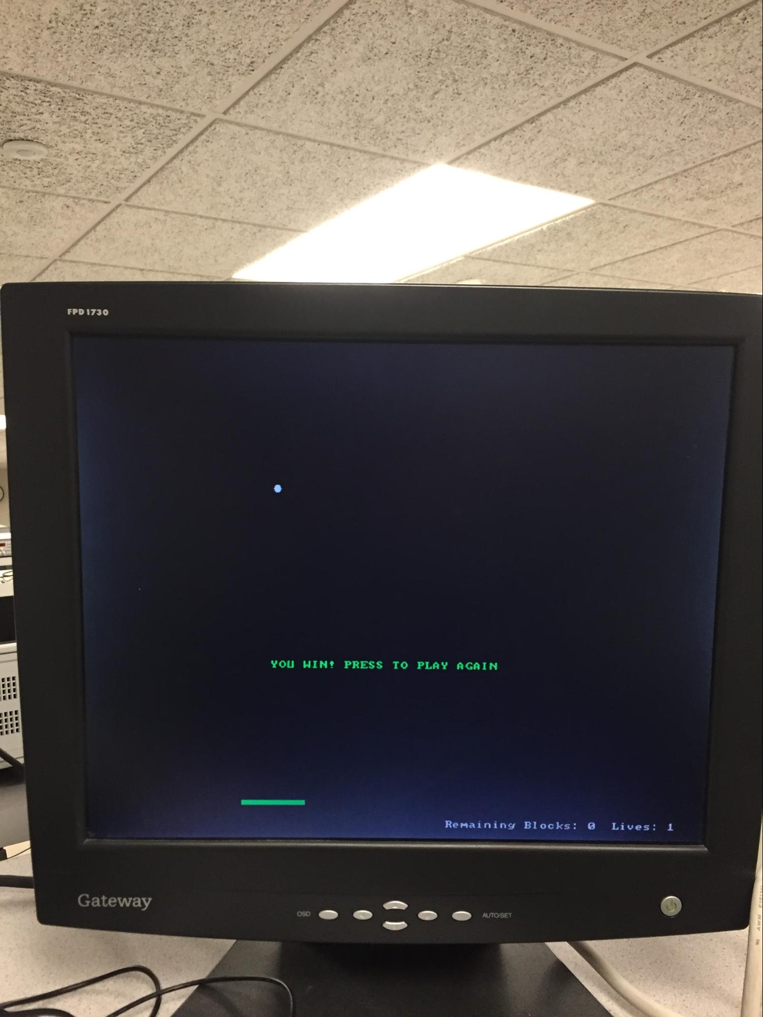
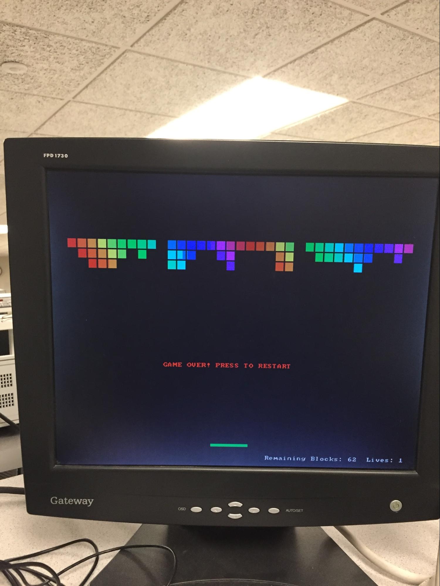
Win Screen Lose screen
Our project is very self-contained and should not interfere with anyone’s designs any more than a desktop computer with a monitor plugged in would. We don’t use any wireless communication such as RF or bluetooth so other designs shouldn’t worry about interfering with our project (within reasonable limits - a hammer could still do a good deal of damage).
For most people, this is a fairly usable product. Anyone that can see the screen, read, and operate the joystick should have an easy time playing the game.
Conclusions
Expectations
Over all, we were quite happy with the display quality we achieved by the end of the project. By combining the color and SPI channels of the processor, we obtained a display controller that had both good spatial and color resolution, which is a significant feat considering our limited hardware.
That being said, there are still a few remaining display glitches that we didn’t manage to debug before the completion of the project. One graphical glitch is that the color channel will sporadically bleed to the right by about 8 to 10 pixels for one of the colors on the screen. We believe that this first issue is caused by the DMA and processor trying to access RAM at the same time, in which case the processor gets priority and the DMA transfer is delayed by a few cycles. Unfortunately, the PIC does not have an option that always prioritizes the DMA over the processor for memory access, so there does not appear to be an easy fix for this issue.
Another issue is that the entire screen glitches occasionally. We believe this is caused by one of the processor interrupts not firing as quickly as it needs to. It may be possible to fix this with a decent amount of debugging of interrupt priorities and timing.
One last issue is that we never figured out a consistent way to set the SPI and color channel offset ahead of time so that all of the signals are aligned. It seems to differ based on what the program does, and we set it by trial and error for our video game. It would be nice to have a more principled approach to setting this value.
Standards conformance
Another potential area of improvement for our project is that the signals we generate are not within the VGA spec with respect to their timing. VGA requires a 25.175 MHz signal with approximately a 0.5% error bound (the clock timing is specified at 39.7 ns ± 0.5%), but we could not conveniently run our microcontroller at a frequency which is a multiple of that. We therefore ended up running the processor at 48 MHz, and driving the output signals at 24 MHz. While the monitions present in lab were able to handle this signal just fine, other monitors may be less forgiving, and could potentially even be damaged because we are running outside of the specified ranges. This could be fixed in the future by using an appropriate external oscillator for the main system clock, instead of the PIC’s internal oscillator.
Other than this timing issue, we met the requirements of the VGA specifications.
Intellectual Property Considerations
The majority of the code and design work in our project in our project is our own work. The main exception is that for the text display, we used a public domain bitmap font which we found online. See Appendix F for the source of this font.
While it is possible that portions of our display controller are novel enough to be patented, we have no intention of doing so.
Ethical Considerations
During the production of this project, we made sure that we were in compliance with the IEEE's Code of Ethics. We believe our project is quite safe. Electrically, all of the voltages used are 5V or less, which leaves us at a low risk of causing electrical shock. Physically, the project does not contain any motors or similar moving parts, so users are at a low risk of injury. Our development activities did not produce significant waste, and should not have a significant environmental impact.
It goes without saying that we avoided conflicts of interest and bribery during the course of our project.
We took care to ensure that each of our claims for the performance of this project, as described in this report and elsewhere, are justified and backed up by testing.
While we certainly did not possess all of the relevant knowledge to complete this project when it began, we believe that our status as students should make it clear that this project was for the sake of learning.
We would additionally like to give credit where it is due, and thank the course staff of ECE 4760, including both the instructor Bruce Land and our lovely TA Mark. Without the resources and and assistance provided to us through this class, none of this would have been possible.
Legal considerations
It is our personal belief that our project does not violate any applicable laws. We are not lawyers, and this section is not legal advice.
Summary
Overall, this lab was the grandest ‘ol time and we learned much about both the power and limitations of DMA and of ourselves.
Appendix A
The group approves this report for inclusion on the course website.
The group approves the video for inclusion on the course youtube channel.
Appendix B (Schematics)
Appendix C (Code listing)
A listing of the code can be found here
Appendix D (Budget)
Description | Qty. | Price (each) |
VGA Socket Breakout | 1 | $4.50 |
Analog 2-Axis Joystick | 1 | $5.95 |
SN74LS08 AND Gate, PDIP Packaging https://www.digikey.com/product-detail/en/texas-instruments/SN74LS08N/296-1633-5-ND/277279 | 2 | $0.63 |
ECE 4760 Small Board | 1 | $4 |
PIC32MX250F128B Microcontroller | 1 | $5 |
Power Supply | 1 | $5 |
Header Socket / Plug (Number of Pins) | 16 | $0.05 |
Solder Board (6 inch) | 1 | $2.50 |
Total: $29.01
Appendix E (Work Distribution)
Brainstorming different ways to use the PIC32 hardware to drive the display was done as a team. Mike did the hardware design and assembly. Max wrote all of the code, including both the VGA display logic and also the video game. Mike found the public domain bitmap font online, and flipped it when we found that all of the characters were backwards. The report was split into sections, with Max writing the high level design, software, and results sections, and mike writing the intro, hardware, and conclusion sections. Everyone proofread each other’s work, and everyone playtested the game a couple of times.
Appendix F (References)
Background Information
VGA Protocol:
https://learn.digilentinc.com/Documents/269
https://web.archive.org/web/20030704041337/www.vesa.org/public/PnD/pnd.pdf
References
PIC32 hardware manual:
http://people.ece.cornell.edu/land/courses/ece4760/PIC32/index_Ref_Man.html
PIC32 PLIB Reference:
http://ww1.microchip.com/downloads/en/DeviceDoc/32bitPeripheralLibraryGuide.pdf
PIC32 Datasheet:
http://people.ece.cornell.edu/land/courses/ece4760/PIC32/Microchip_stuff/2xx_datasheet.pdf
SN74LS08 (AND Gate):
http://www.ti.com/lit/ds/symlink/sn74ls08.pdf
Included Intellectual Property
Public Domain Bitmap Font: