
Introduction
For our final project, we would love to build something that integrates arts, science, mechanics, electronics and fun. We were surfing the internet for inspirations and came across with something that captured our attention: water curtain. Water curtain combines water, physics of gravity, mechanics of structure and beauty of electronics control to create beautiful artistic effects, letters, graphics...
The magic of water curtain lies in the solenoid valves on top of the mechanical structure. Solenoid valves are essentially “water switches”. In its normal state (open state), solenoid valve allows water to flow through. But once it is powered, it would generate a magnetic field strong enough to suck up a piece of metal inside to block the valve and stop water from flowing. Water flows down to ground naturally due to gravity. So by individually controlling every solenoid valve on top of a stand, we would control individual line of water flow and create beautiful artistic effects and patterns.
Most water curtains we found online are super scaled versions of water curtains that are very expensive and limited for high end shows and events. We found some limited attempts to create small versions of water curtains. Some failed miserably. Some succeeded but had almost zero documentations of their works. We took the initiative to create an innovative open sourced waterfall design, which follows the design specifications of 1. Interactiveness/fun, 2. Modularity and 3. Replicability. We successfully built the waterfall and a user friendly app interface that interfaces with the waterfall. There are three modes in the app. Users can direct control the waterfall in real time and play with it in Play Mode. Users can also draw patterns or letters on a square arrays sketch pad and display them on the waterfall in Program Mode. Last but not least, user can click one button to enter Enjoy Mode, which would start a soothing 1 minute waterfall show.
High Level System Design
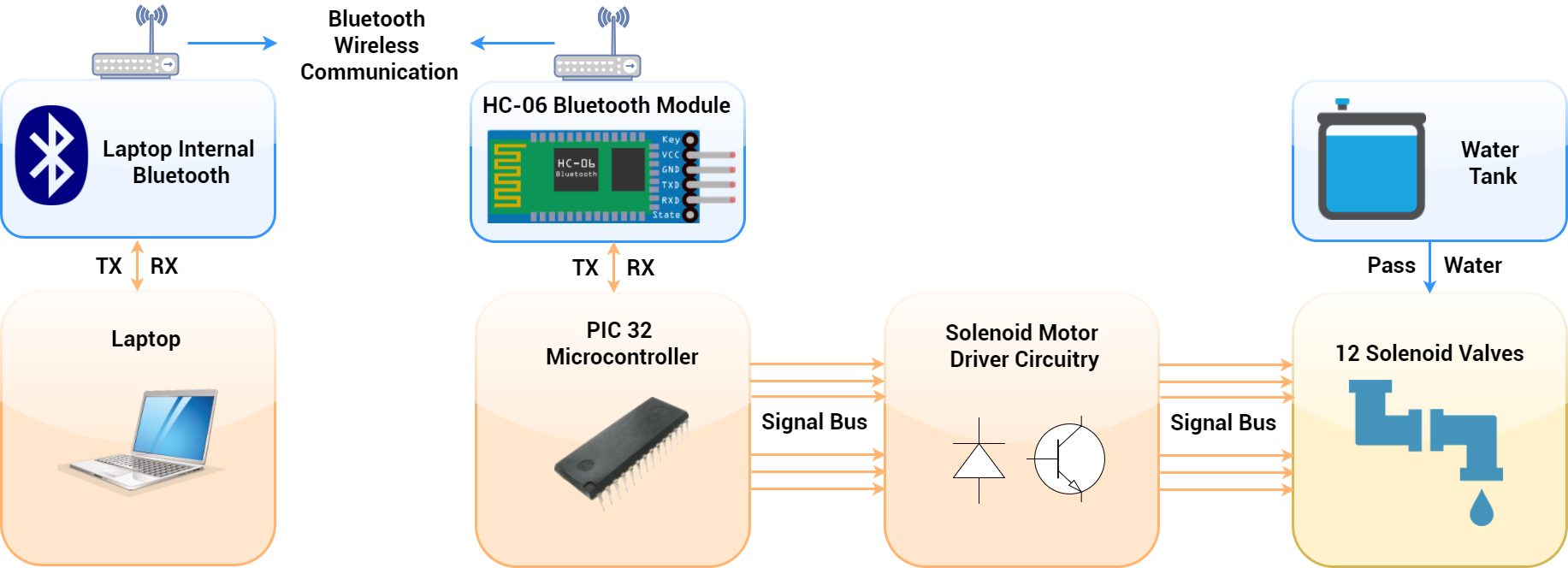
In high level, the waterfall system can be viewed in two parts: the first part is the waterfall itself that includes the mechanical/hardware design and the PIC32 microcontroller that is constantly receiving information via bluetooth and processing the information to control all the solenoid valves. The second part is the the laptop and an App Interface, which user can touch and tap on to transmit instructions that would be processed by the PIC32. The laptop and the PIC32 microcontroller are not physically attached. Instead, they communicate wirelessly using bluetooth.
We will be using two physics equation, the Kinematic Equation and the Hydrostatic Pressure Equation. The Kinematic Equation is used to calculate water free fall time. The equation is [d = v_i * t + ½ * a * t^2], where d is height of fall, v_i is 0 since there is no initial speed of water, a is the acceleration due to gravity or 9.8 m/s^2 on Earth, and t is the unknown free fall time where we need to solve for. The Hydrostatic Pressure Equation is used to calculate how much water pressure it needs to exert on a solenoid valve before water can overcome the resistance of the solenoid valve and flow smoothly. The equation is [p = ρ * g * h], where p is the liquid pressure, ρ is the liquid density, g is the acceleration due to gravity and h is the height difference between the highest water height level of the tank and water height level when it leaves the tube.
Without further due, let’s begin talking about how we actually build the waterfall from scratch :D and start with the mechanical design.
Mechanical Design
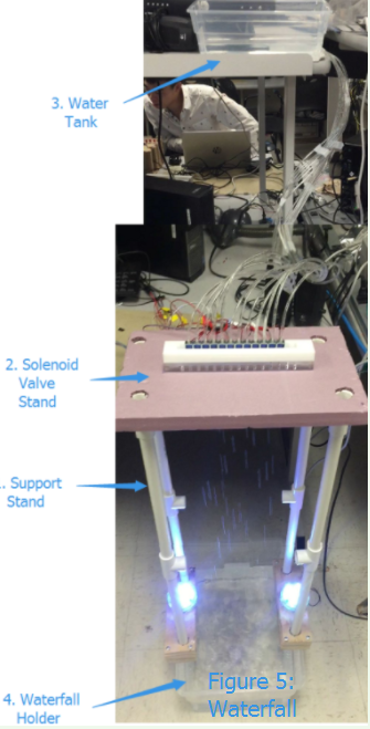
The mechanical design of the waterfall has four parts: 1. Support Stand, 2. Solenoid Valves Stand, 3. Water Tank and 4. Water Holder.
1. Support Stand
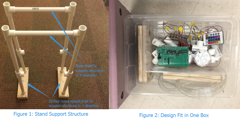
The support stand is made to create a good height for the waterfall. We want to make the design modular so it can be built in either small scale or large scale with ease. We spent some time over fall break back home in NYC to source materials that would fit this spec. When looking around at Home Depot, we came across with the PVC pipe and the PVC tee connector that were exactly what we were looking for. We created a roughly 2 feet height mini waterfall by connecting two 1 feet long pipe with a tee connector in between. Both X, Y directions of the support stand are fixed to create a robust structure: the X direction of the stand is fixed by connecting another 1 feet long pipe between two structures and the Y direction of the stand is fixed by inserting it into two pieces of wood at the bottom, where we had drilled holes onto. (Figure 1)
One motivation to make it modular is that this project is open source, anyone who would like to make their designs twice as high can simply get two more tee connectors and two more 1 feet pipes and easily snap them together to make it higher.
Another motivation to make the design modular is that it helps a lot with portability. We don’t want to make a giant beast that is impossible to carry around :D. It was a lot of fun that we actually came up with a very portable design where all components can be fit inside a single container box magically. (Figure 2)
2. Solenoid Valve Stand
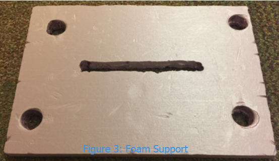
The solenoid valves sit inside a laser cutted solenoid valves holder, which sits on top of a piece of foam. We build the support platform for solenoid valves holder with foam instead of other materials, because we can easily cut foam with a knife to create a rectangular opening space in the middle that allows water to pass through.
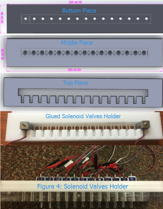
A solenoid valves holder needs to be created to keep the solenoid valves stationary and in place. Initially, we were just thinking about using the foam as a holder and embedding the solenoid valves inside the foam, but this didn’t work well, because it is very hard to create 12 similar holders inside the foam. If one of the holder is not smooth enough, it would tilt the solenoid valves and water would fall at an angle to ground instead of falling straight to ground. We were brainstorming different designs for weeks that can potentially address this, possibly avoiding laser cutting. But given the short time constraints of the project, we decided to simply go with laser cutting. We created our laser cutted design in solidworks and it has three parts (Figure 4): The bottom part is simply circles. A small piece of tube is inserted into each circle so water can fall straight through ground following the tube. The middle part is the solenoid valve footprint that matches the bottom of the solenoid valve. And solenoid valves can be snap on top on it and stick to it. The top part is the T shape that holds the solenoid valve body in place and the | part of the T shape part allows wires to come out and connect to the motor driver circuitry. We found some scrap acrylic parts in Cornell’s Rapid Prototyping Lab (RPL) and use the laser cutting machine in RPL to laser cut out these three parts. Finally, we glued the parts together using Loctite super glue and the holder works great. (We actually cut out an extra bottom piece and an extra top piece to make the holder bigger and more stable since the thickness of one piece of acrylic is not thick enough.)
All these designs are open sourced as well and will be uploaded to our github page by Dec. 15th.
3. Water Tank
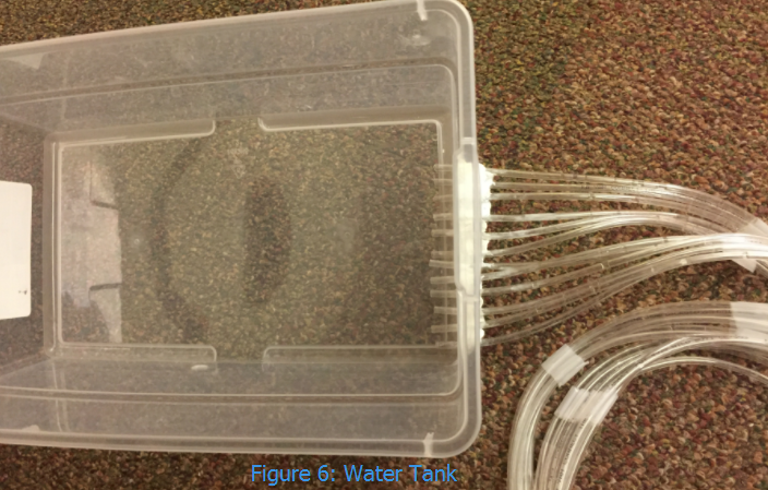
Our waterfall water tank is a small 6 Qt container we bought in Target. There are twelve 1m long tubes extending from one side of the container and connecting to the solenoid valves.
To create 12 holes for the small tubes in the container, we lit up a screw driver with fire and melt into the container when it is hot. (We tried using a drill to create holes, but that doesn’t work very well with plastic and it can tear down the plastic with the strong rotation force the drill generated.)
The tricky part is to seal the gaps between the holes and the tubes to prevent water from leaking out the container. We first tried to use a WaterWeld Epoxy Putty Stick that is specifically made to seal leaks and patch holes, but it didn’t work well with plastic surprisingly and water still leaks out. We then tried the Loctite super glue, but it again didn’t work well because water fades out the glue as time passes. We then experimented applying Loctite super glue followed by WaterWeld Epoxy Putty Stick. This turns out to be working so well and successfully prevents water from leaking.
Our waterfall setup doesn’t use any pump to generate any external pressure on the waterfall, but only relies on gravity to generate enough potential energy pressure to let water naturally flow down from the water tank to the solenoid valves. And water only falls if it exerts a high enough pressure to flow down. We looked back at the good old days hydrostatic pressure physics equation to find out what we can do to increase water pressure: p = ρ * g * h, where p is the liquid pressure, ρ is the liquid density, g is the acceleration due to gravity and h is the height difference between water level. Based on the equation, water pressure would go up if we increase the density of water, acceleration due to gravity or height difference. Density of water can go up if water gets colder, but the effect is minor: Density of room temperature water in 25°C is 997.05 kg/m^3, whereas density of cold water in 4°C is 999.97 kg/m^3, so increasing density is not a good option to increase water pressure. And we know that we can’t do much about gravity as long as we are in the Earth planet. That left us with the height difference, which is also the easiest to change. After experimenting putting the water tank at different height, we found that if the water tank is placed close in height to the solenoid valves, water would be doing water dropping instead of flowing and sometimes it might not be flowing at all. We also found that the water tank needs to be about 80cm or 0.8m higher than the height of the solenoid valves for water to flow smoothly via the solenoid valves. So in our design, water needs to exert pressure of 997.05 kg/m^3 * 9.8 m/s^2 * 0.8m or 7.82 kiopascal to overcome the resistance of solenoid valves and tubes before it can flow smoothly.
4. Water Holder
Our water holder is a median sized 16 Qt container we bought in Target. It would catch all the water flowing down straight from the solenoid valves so we don’t create a big mess in the lab :D.
Hardware Design

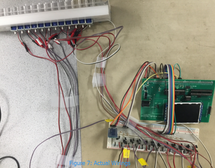
The hardware electrical components used for this project are a PIC32 microcontroller, a HC-06 bluetooth module, 12 solenoid valves, 12 motor driver circuits. The PIC32 and HC-06 bluetooth module are powered by a wall plugged 5V power supply. The HC-06’s TX, RX Pins are connected to the serial communication pins of the PIC32, which we programed to be RA1/RX and RB10/TX , respectively. Inside a motor driver circuit, there is a 1N4001 diode, a solenoid valve, a 2N2222 transistor and a 330 ohm resistor. A solenoid valve is essentially a motor with coils of wires inside, so we use a general purpose 1N4001 diode as flyback diode to protect the transistor from motor voltage spikes and back EMF. The solenoid valves we used are rated at 3V drawing roughly 80mA current. This is way too much current for the PIC32 GPIOs can handle, therefore they are powered by an external power supply at 3.3V. The general purpose 2N2222 transistor is used as an electrical switch to turn on/off the solenoid valve and twelves GPIO pins on the PIC32 are used as signal bus to send switch on/off signals to the 2N2222 transistor to turn on/off the solenoid valves.
The GPIO pins of the PIC32 outputs 3.3V and they are connected to the 2N2222 transistors with a 330 ohm resistor, delivering 10mA of current per GPIO pin and 120mA of current in total. From page 243 of Datasheet on Section 29 Electrical Characteristics of the PIC32MX250F128B microcontroller, we know that maximum output current sunk/sourced by any I/O pin is 15 mA (greater than 10mA we are drawing) and the maximum current sunk/sourced by all ports is 200 mA (greater than 120mA we are drawing), so we are safe. The 2N2222 transistor can handle 800mA of current, which is far greater than the 80mA current the solenoid valve is drawing.
We set up the circuit on a breadboard following the schematics drawn above. The solenoid valve comes with short power wires, so we soldered long wires to enable it to reach the breadboard from the waterfall. We soldered male connectors to the other side of the long wires that allow it to be easily plug into the breadboard. Also, 12 solenoid valves are drawing 80mA*12 or roughly 1A of current when all turn on. We are skeptical if the breadboard power line can handle 1A of current, so we added extra wires across the breadboard to help transmit current. We can solder our design into a piece of perf board, but with the accessible open source design mindset, we decided to stick with breadboard so the design can be rapidly prototyped and referenced by people more easily.
Software Design
Part 1: Sending/Transmission (App on Processing)
We used Processing, an open source computer programming language built for the electronic arts, to design our app user interface. Once the Processing App is opened, it would first wait for 5 seconds, because it takes roughly 5 seconds for the App to establish a Bluetooth connection with the HC-06 bluetooth module that is connected to the serial port of the PIC32. The app is separated into three distinct modes: Play Mode, Program Mode and Enjoy Mode.High-level Design Pattern:
The high-level interface mainly involves how to switch between the three modes. To accomplish this, we defined a global variable called modeFlag, which is an identifier for which mode we are currently in. modeFlag is initialized as 0 since the app directly enters the Play Mode once activated. When modeFlag is 1, the app enters the Program Mode, and when it is 2, the app enters the Enjoy Mode.
The switching between the three modes is implemented inside of the mousePressed() function because the users need to click a button we drew in the app in order to enter a different mode. mousePressed() is a Processing-supported function that is called once after every time a mouse button is pressed.
Play Mode:
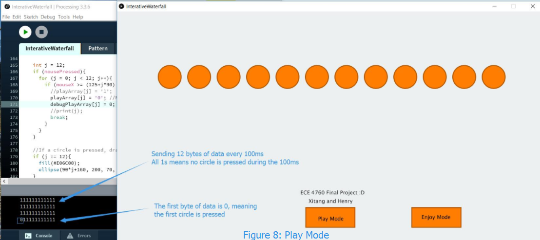
Play Mode is the most primitive functionality of our program, which basically is an interface for direct controlling solenoid valves. The interface consists of 12 circles, where each of them corresponds to an individual solenoid valve of the waterfall in the order of left to right. Whenever a circle is pressed in on the app screen, its corresponding solenoid valve would close and allow water to fall down. User can have fun pressing circles on the app and interact with the waterfall in real time.
Here is how Play Mode works behind the scenes: We first constructed a 12-cell char array called playArray to store the status of each circle, with a char 0 denotes to the no press state of the circle and a char 1 denotes to the press state. In Play Mode, at the beginning of every 100 msec, all 12 circles are reset to char 0 or the no press state. When a circle is pressed during the 100 msec interval, its corresponding position in the array would be changed to 1. And at the end of the 100 msec, the app will send all 12 bytes of data plus 1 byte of stopping condition via bluetooth to the PIC32. When the PIC32 receives the data, it would decode each byte of data and turn on/off the digital pin to close/open individual solenoid valve. We will talk more about how the PIC32 handles this in the PIC32 Software Design Section next. The average visual reaction time for humans is about 250 msec, by transmitting data in a rate twice as fast or 100 msec, user touching and playing with the circles in Play Mode would feel as if they are controlling the waterfall in real time.
Program Mode:
Our second mode, the Program Mode, is a more complicated interface which enables the users to customize the pattern they would like to visualize and send them to the PIC32 for further processing and display. The 20 x 12 matrix in the center of the application is a scratchpad where the users can draw the pattern they want to display. The 12 columns correspond respectively to the 12 solenoids and there are 20 rows of room for user to draw a lot of things.
The core data structure we used in this mode is a two-dimensional array of type integer called programArray to represent the scratchpad. Each cell consists of either 1 or 0, which corresponds to the color of the cell. A 1 indicates that the cell is filled and a 0 means that it’s unfilled. This 20 x 12 array will be sent to the board in 240 bytes of data plus 1 byte of stop condition when the send button is clicked. which will be used to control the solenoids to display the pattern in the PIC32.
The scratchpad supports both painting and cleaning in real-time. The first time you pressed your mouse on a random cell, if the color of this cell is white, which means unfilled, then the interface will turn into painting mode, that will fill color for all cells where a mouse is being pressed until you release your mouse; if the color of the first cell is orange, however, then the interface will turn into erasing mode, which will turn all cells where a mouse is being pressed into white until you release your mouse. This is a user-friendly feature that we implemented to facilitate the users’ drawing process if he/she is unsatisfied with the design and is thus able to modify in a trivial way. (The invention of this user-friendly drawing feature attributes to the awesome mobile app of Robo Wunderkind, a startup Xitang interned over the summer.)
The actual implementation of the above feature mainly involves embedded functions that Processing supports and the programArray we declared. The display of the scratchpad is implemented in the draw() function, which continuously executes the lines in its block until the program is terminated. It is very similar to the loop() function in Arduino. First of all, we need to know where the mouse is clicked and which cell that is. Processing provides two system variables mouseX and mouseY to support it, where mouseX contains the horizontal coordinate of the mouse and mouseY contains the vertical coordinate of the mouse. After obtaining the location of the mouse, we use the two data to determine the cell where is mouse being clicked, which is a trivial mathematical calculation. Then, we detect where the mouse is being pressed or not and this action will be captured by another embedded system variable of Processing called mousePressed. At the same time, the mousePressed() function will also be activated. In the mousePressed function, the cell which is being clicked will be checked. If its corresponding value in programArray is 1, then we will set a variable that we defined called fill to 0 and if the value is 0, then fill will be set to 1. fill is declared as a global variable, which can be access anywhere in program that decides whether to fill in the cells or clear out the cells. This is the high-level design pattern we utilized when programming this mode and after these step, the last step is simply to display the colors correctly in the draw() function, which uses the fill() function supported by Processing.
Program mode also includes seven pre-defined patterns for the users to choose. These seven patterns can also be edited. We also implemented a Clear button in case the users want to empty everything in the scratchpad.
Enjoy Mode:
The last mode we designed is the Enjoy Mode. When the Enjoy Mode button is pressed, it would trigger the PIC32 to display a one-minute waterfall showcase with all patterns pre-programmed in PIC32.
Part 2: Receiving (Control on PIC32)
The software design of the Processing App is responsible for transmitting data, and the the software design of the PIC32 is the fun part, which is responsible for receiving the data and decoding it to do what it is supposed to do.The first thing we coded out in the PIC32 is to set up serial communication. (Bruce has done a tons of work with Serial Communication and we use his wonderful sample code as good starting point.) There are two UART ports in the PIC32 and we used UART2 to set up serial communication. We first need to set up the serial pins in the PIC32 by assigning U2RX to pin RA1 and assigning U2TX to RB10. We then configure UART2 to transmit in a baud rate of 9600 with 8 bit data size, no parity bit and 1 stop bit. (This is the standard serial setting we are setting up as the receiving end on the PIC32, and we also make sure this setting matches with the bluetooth serial port in our laptop's device manager, which would define the setting for the sending end on the Processing App.)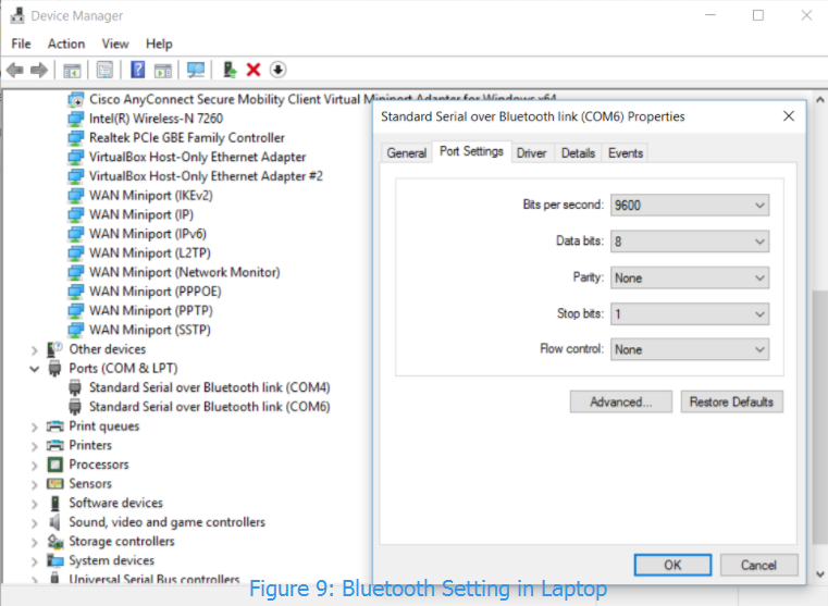
Once UART is configured, we wrote a serial thread to read data and decode data. To read data, we spawn a thread that calls the PT_GetSerialBuffer() function, which would continuously read and store every byte of data received into a buffer called PT_term_buffer and it only stops reading when it receives the stop condition ‘/r’. As mentioned previously, we have three different modes and the PIC32 would be able to decode which mode we are in based on the size of the PT_term_buffer. In play mode, we sent 12 bytes of data at a time; in program mode, we sent 240 bytes; and in enjoy mode, we sent 20 bytes of data, which is an arbitrary number greater than 12. (We want it to be greater than 12 because it is possible to send data anywhere from 0 to 12 bytes in play mode when user randomly switched out from play mode to other mode with our Processing App implementation.)
To measure how many bytes of date we received, we created a for loop that loop through PT_term_buffer to check for ‘2’, which is our stop condition data byte. When we find ‘2’, we break out from the for loop and our loop counter bufferCounter would has the number of byte the data we received. If bufferCounter is equal to 12, the program enters Play Mode. In Play Mode, modeFlag is set to be 0 to indicate it is in Play Mode and the function setValves() is called. Function setValves would turn on and off individual digital pin to control the corresponding solenoid valve based on PT_term_buffer. For example, if the first 12 char bytes of data received in PT_term_buffer are all ones, it means we want to turn all the signal pins HIGH and stop all waters from flowing.
If bufferCounter is equal to 240, the program enters Program Mode. modeFlag is set to 1 to indicate it is in Program Mode. Note we didn’t need to call any function in Program Mode in the serial thread, because Program Mode works off using a timer interrupt. The data we receive in Program Mode is a 20 rows by 12 columns matrix, where the 12 columns correspond to the 12 solenoid valves. When modeFlag becomes 1, the timer interrupt would set the solenoid valves based on Row 19’s 12 values at the first 100ms. Then it would set the solenoid valves based on Row 18’s 12 values the next 100ms. It would loop till Row 0 and cycle back to Row 19 and repeat the cycle over and over again. Ideally, this would mean we would want to set a timer interrupt to run at 100ms. The PIC32 has a main clock frequency of 40MHz, so we would have to set the timer to time out at 4MHz, which is not possible as the 16 bit timer overflows at 2^16 or 65536, so we set the timer interrupt to be triggered every 1ms or time out at 40000, which is less than 65536. Every time the timer interrupt is triggered, it increases a msCounter variable. When msCounter is counted up to 100, it sets a row’s 12 valves and also decreases a row counter, which enables the next 100 msCounter triggered to set the valves of the next row. The row counter reset itself to row 19 when it finishes executing in row 0. Note that we loop from row 19 to 0 instead of the other way around because that is the natural order how water fall down, the bottom row first. Last but not least, if bufferCounter is equal to 20, the program enters Enjoy Mode. Enjoy Mode has hard-coded pre-built patterns like the patterns in Program Mode and it also run in a similar scheme with timer interrupt as the Program Mode. For example, in one of the show where solenoid valves advance from left to right, we created a counter that increase from 0 to 11 over a set time interval and map the counter to turn on an individual solenoid valve.
Result
Our Beautiful Interactive Waterfall Project is a big success and we successfully reach most expectations we set forth.
We successfully created a very modular portable mechanical and hardware design for our waterfall, which can be easily customized and mechanical parts can be obtained in accessible vendor like Home Depot and Target.
We successfully got the Processing App to interface with the PIC32 via bluetooth. Data were sent correctly based on users’ actions on the App to the board and PIC32 was programed to correctly decode the data and process it.
We successfully implemented three modes on both the Processing App and PIC32: Play Mode, Program Mode and Enjoy Mode.
The App was designed from an intuitive user-friendly perspective. For instance, the scratchpad in the Program mode combines both painting and erasing functionality and easy to manipulate, which enables the users to construct their pattern conveniently without having to reopen the application multiple times when trying to modify their initial drawings.
This project is easy to manipulate for anyone as long as he/she has learned how to use the Processing app we designed. The user interface has been designed to make the manipulation as trivial as possible and all buttons are labelled in a clear manner to instruct the users about what to do. Thus, from this perspective, this project has great potential to be implemented as a open-source project for further update.
Still, there are some fun issues we ran into and we would like to share:
Issue 1: Solenoid Valves Holder Tolerance
We measured the solenoid valve width to be 12mm and created 15 slots in the solenoid valve holder design with 12mm gap. This design comes out to be not being able to fit all 15 solenoid valves, because there are some slight discrepancies in the solenoid valves’ widths: some measured 12.1mm, while some 12.2mm... The discrepancy in width has error propagation effect and the holder initially can only hold 7 solenoid valves at max. We used the dremel tool in Cornell’s Maker Club and manually grinded down the side of the solenoid valves and got it to thin enough to fit 12 solenoid valves. So now, we learned to always consider tolerance when making a design.
Issue 2: Cost constraint
A major cost component of this project is the solenoid valves. A typical water solenoid valve costs at least $8 and 12 of them would be ~$100. We can only spend at max $125 for our project so we turned our attention to gas solenoid valve, which is in the cheaper $2.5 range. We bought some gas solenoid valves from an ebay vendor Dan, who is very kind and offer us some discount and free tubes after we told him that we are using the valves for school project. Since the gas solenoid valve is not designed for good water application, we hack the gas solenoid valves to be water solenoid valves by cutting its bottom and sanding it to create more space for water to flow through. (Note that we have to leave one plastic corner intact because it keeps the metal responsible for blocking the water in place. The metal would fall out if we completely remove all plastic parts in the bottom.)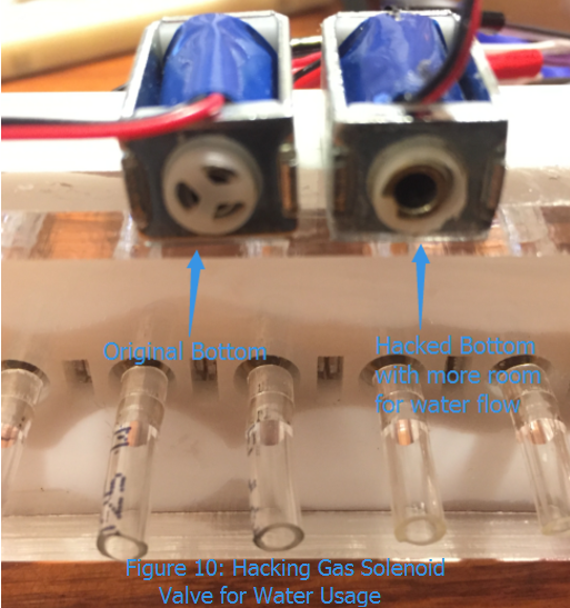
Issue 3: 3-bit Resolution Design
Our design has a height of 50cm. When a solenoid valve is closed, water would flow through and experience free fall of 50cm or 0.5m. Using the free fall physics equation h = ½ * g * t^2, where h is 0.5m and g is 9.8m/s^2, we can compute that it takes the water 319ms to fall to the floor. Our sketch pad has 20 rows, to fully display everything in the sketch pad patterns in one shot, we would need to set the timer interrupt to run at 319ms / 20 ≈ 16 ms, meaning switch to the next row of the pattern every 16ms. This is doable in the PIC32 but not the solenoid valves. Solenoid valves have coils of wires inside, which take times to charge before generating a strong enough magnetic field to suck up the piece of metal that blocks water flow. We tried to set the timer interrupt to run at 16ms, but it can’t really control the solenoid valve because 16ms is too fast for it to operate. And through testing with different interrupt trigger time, we found that these coils of wires need roughly 90 ms to charge and discharge, so we are bounded to set the timer interrupt to run at 100ms. As a result of this, our design only has about 3 bit vertical resolution (319ms / 100ms ≈ 3). It will display patterns or letters that are too complex in a twisted and blurred manner, but it can still display simple pattern and letter such as C and U very nicely. Looking back, initially we are looking to build a mini version of waterfall as no one seems to have done it before. Now we guess it makes sense why no one does it, because the resolution is simply too small for a mini waterfall and it is limited in what it can be displayed.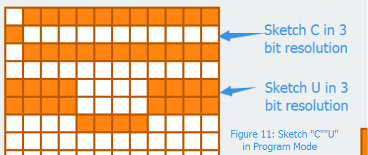
Conclusion
The waterfall project is a super duper interdisciplinary project that integrates arts, science, mechanics, electronics, software and fun all in one place to make a legit product project. In the process of making this project, we are almost never certain whether we can finish the project within the time constraint, mainly because it involves a great breadth and depth of knowledge in different disciplines and different issues can pop up from nowhere that hinder our progress. In making this project, we benefited so much and enriched greatly in our product making skills. And we are super excited that it works out elegantly at the end. All the days and nights we pulled for this project are so worth it now. It also means a lot to us when Bruce found this to be one of the omg projects, hahaha. Bruce was very skeptical of any water related project as a previous 4760 water related project seems to water bomb the lab so bad. We are very glad that we did not and managed to integrate water gracefully with electronics to create beautiful artistic effects!
The solenoid valve response delay and the height of our design limit the vertical resolution of our design to be 3. For future improvement of vertical resolution, we can find better solenoid valves that has faster turn on/off response time or we can simply stack more PVC pipes to create a higher design so water will have a higher free fall time. We might also explore our solenoid valves more, see what is the max voltage it can take and see if operating in higher voltage would decrease charge time.
Our project (both hardware and software design) are designed by ourselves from scratch. The software implementation on PIC32 utilizes knowledge we have learned throughout the semester to help us formulate the design pattern which we used to support our expected functionalities. As for the implementation of the user interface on Processing, we also constructed the entire graphical user interface and the high-level design pattern by ourselves. The specific implementation utilizes the reference of Processing tutorial as a lot of features, like pressing a button, filling in color etc. utilizes the embedded functions in the Processing library
A bluetooth module is used for this project and bluetooth RF is subjected to Part 15 Title 47 of FCC’s Code of Federal Regulations (CFR). For bluetooth 4.0, the specifications are: Gaussian frequency shift keying (mod index 0.5), less than 1 Mbps, within 2402-2480 MHz, 40 channels [3 advertising channels (2402, 2426, 2480 MHz) for fast connection, 37 data channels], 2MHz spacing, 6dB bandwidth, peak output power < 1W.
Our project strictly follows the IEEE Code of Ethics. The hardware component of our project and the actual functionalities will not have any potential influence to others’ safety as we did not use any hazardous units or components in our hardware design. We have also stated the entire process of the designing phase in our report and clearly stated the issues within our current design in this report. Moreover, we have provided certain degree of insights into how we can potentially resolve this issue, which serves as the source for further improvement. Last but not least, this project is also implemented from the perspective of promoting it to be an open-source project, which welcomes anyone interested to modify and upgrade the features with no intentions of discriminations or exclusions. Hopefully, people find the steps we taken to make this project easy to read through and we hope people reading the report can get something out of the project and use for their own projects :D.
Appendix
Appendix A - Approval
Our group approves this report for inclusion on the course website :D.
Our group also approves the video for inclusion on the course youtube channel :D.
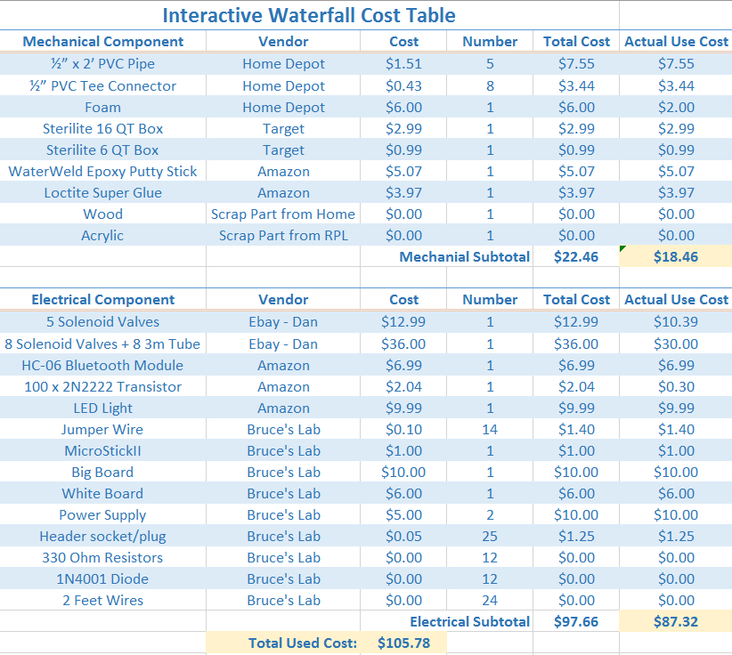
Appendix B - Cost Table
Appendix C - Reference
Document Reference Link:
Bruce Serial Code
PIC32 Datasheet
PIC32 Reference Manua
PIC32 Peripheral Library
Processing Reference
Dejan Nedelkovski’s Interfacing HC-05 with processing Tutorial
Kinematic Physics Equation
Water pressure reference
2N2222 Wikipage
2N2222 Transistor Application Tutorial Youtube Video
Vendor Purchase Link:
Solenoid Ebay Vendor Site
Thank you very much Dan for the discount and some free tubes to support us
HC-06 Bluetooth Module
WaterWeld Epoxy Putty Stick
Loctite Super Glue
LED Light
2N2222 Transistor
Icon Link:
Computer icon
Bluetooth icon
Pic 32 icon
Water tank icon
Intro icon
System icon
Conclusion icon
Diagrams are created in draw.io
Code we used for our demo can be found here. A more concise and commented version would be uploaded to github by Dec 15.