
"Defying gravity in 6-weeks"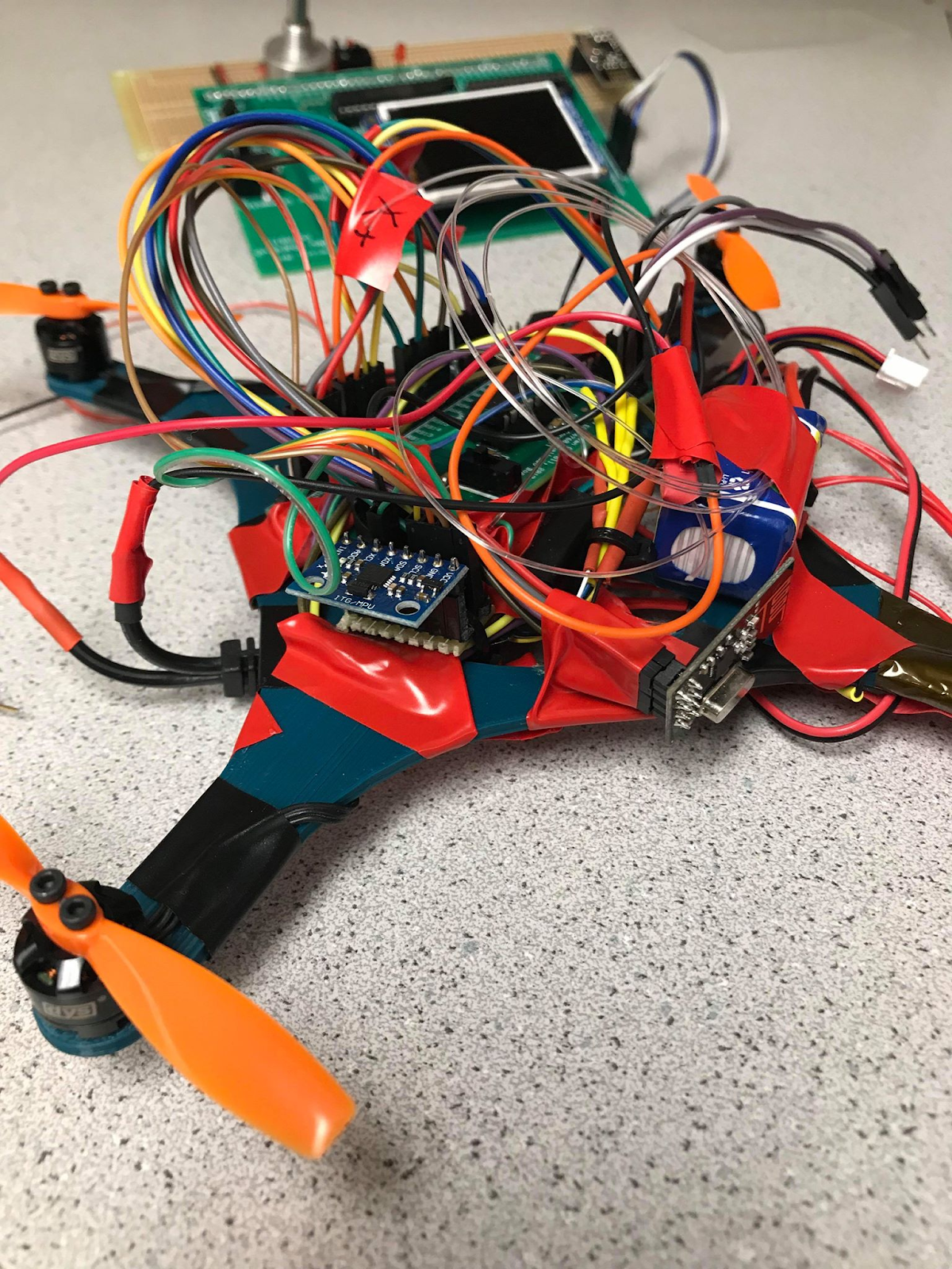
We designed, constructed and tested an autonomous quadcopter that used an IMU to control its attitude and a radio to transmit data to a controller, which we also built. The project focused on making the quadcopter as autonomous as possible, so only high level commands such as flight time are sent from the controller to the quadcopter. A 3D-printed chassis houses all of the quadcopter electronics. The four motors are controlled by an off-the-shelf electronic speed controller (ESC) which receives PWM signals from the PIC32 microcontroller. A PID controller reads IMU data to control the quadcopter's attitude, ensuring stable, level flight. The user can send commands using a potentiometer and switches on the controller, and can receive IMU data from the quadcopter in real time.
High Level Design top
Rationale
The quadcopter project interested us because of our previous experience building flying things. Stewart builds remote control airplanes on the Cornell Design/Build/Fly project team and because of Thinesiya's RF communications experience and Yijia's interest in controls. We were also interested in the autonomous aspect of the project. From the beginning we wanted the quadcopter to stabilize and fly itself with only high-level instructions from the flight controller.
We simplified our idea to increase the project's chances of success. We decided to build a small quadcopter capable of receiving a start signal, taking off and controlling its attitude, hovering, and landing. Some parameters could be tuned with the radio, such as the flight time of the quadcopter.
Mathematical Background
The PID controller set the PWM on-time based on the difference between the desired angle and the current angle measured by the ADC, as well as the derivative and integral of this quantity. The control signal which determines PWM on-time is the sum of three terms:
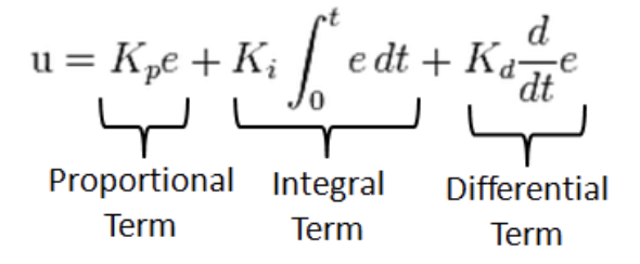
Equation: The equation for a PID controller
1) The proportional term, the proportional gain factor K_p multiplied by the difference between desired angle and currently measured angle (angle error).
2) The derivative term, the derivative gain factor K_d multiplied by the derivative of the angle error.
3) The integral term, the integral gain factor K_i multiplied by the integral of the angle error.
Design Overview
A few initial calculations and tests determined the feasibility of the project. For ease of testing we chose to make our quadcopter as small as possible, just big enough to carry the PIC32 microcontroller and associate electronics. The mass estimate in Table 1 predicts a total mass for the quadcopter of 0.348 kg.
Estimated Quadcopter Mass Breakdown
| Component | Quantity | Unit mass [kg] | Total mass [kg] |
|---|---|---|---|
| Chassis | 1 | 0.05 | 0.05 |
| Motors | 4 | 0.01 | 0.04 |
| Batteries | 1 | 0.08 | 0.08 |
| Propellers | 4 | 0.005 | 0.02 |
| Motor controller | 1 | 0.02 | 0.02 |
| Small board | 1 | 0.01 | 0.01 |
| IMU | 1 | 0.005 | 0.005 |
| Radio | 1 | 0.005 | 0.005 |
| Motor Wires | 20 | 0.001 | 0.02 |
| Other Wires | 20 | 0.001 | 0.02 |
| Nuts/bolts | 20 | 0.001 | 0.02 |
| Margin | 20% of total | 0.058 | |
| Total: | 0.348 |
The chosen motor, battery and propeller combination must therefore be able to lift this mass with a thrust to weight ratio greater than 1. We found several motors weighing around 10g that met this requirement (further details in the hardware design section), so building a quadcopter of this size seemed feasible.
Hardware/Software Tradeoffs
The major constrain for the drone is between the lift power and its weight. We want to minimize the weight by reducing the unneccesary hardware and use the battery with higher voltage within the limit. The drone reads from IMU to adjust the attitude so that it is in banlance. the IMU reading is done in the Interrupt Servie Routine, the frequency for the program to enter the ISR is also the constrain for control as we need to know the IMU data as faster as we can, while the time length of ISR will increase as more functions such as radio transmit is added into the ISR
Hardware Design top
Hardware Selection
We chose to use a brushless DC motor due to the prevalence of these motors in the world of RC aircraft and drones. This allowed us to choose from a wide variety of off-the-shelf controllers made to control these motors for small aircraft applications. We looked for a motor that minimized size and weight but still provided enough power for the quadcopter to take off. The DYS BE1104 motor was a good candidate because of its small size and weight (11mm diameter and 6g mass). Additionally, since this motor is frequently used for small aircraft, it has documented test data with particular propellers and batteries. The data shown below is from GetFPV.com, a website about model aircraft and drones.
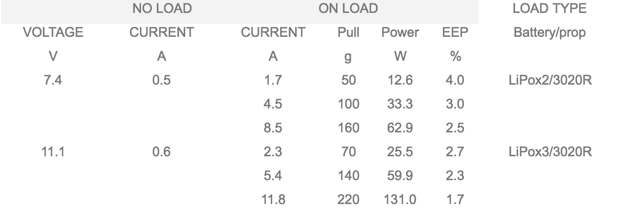
Table 2: Test data for the DYS BE1104 brushless DC motor
Based on the data in Table 2 we chose to use a 3020R propeller which has a 3-inch diameter. We bought both a 2-cell 7.4V LiPo battery and a 3-cell 11.1V LiPo battery to test with. With our quadcopter weight estimate of 348g, it would take at least 4.5A at 7.4V or 5.4A at 11.1V to take off. This allowed us to size the batteries for reasonable flight times. At 4.5A per motor (18A total), a flight time of 1 minute requires a 7.4V battery with a capacity of 112.5mAh. We bought a battery with 450mAh to give some safety factor for current draw and to avoid a large depth of discharge, increasing the battery life. The best 11.1V LiPo we could find that fit our weight budget had a capacity of 350mAh. Both batteries had a discharge coefficient of 20C, which seemed qualitatively sufficient given prior experience using 20C LiPo batteries to fly model aircraft with current draws of up to 30A. If we were more concerned about the longevity of the batteries, more analysis could choose an optimal C rating.
Brushless DC motors are typically controlled using an Electronic Speed Controller (ESC). We considered the trade of whether to build a circuit ourselves to do this or buy an off-the-shelf controller. The advantage to building our own circuit was that we would understand exactly what the inputs and outputs of the circuit were, and would be able to control the motors exactly the way we wanted. Past experience with off-the-shelf controllers has shown that they are usually poorly documented, run on obscure firmware with equally poor documentation, and have a lot of logic built in that makes their behavior hard to predict. Many problems with RC aircraft can be traced to misuse of ESCs. Subpar motor performance might be the result of the controller having been accidentally recalibrated by some specific sequence of power cycling that is nowhere to be found in the ESC documentation. Nonetheless, we decided that our circuits experience was insufficient to allow us to build a motor controller well in the allotted time, so we chose to buy an off-the-shelf ESC. Another concern was the size and weight of an off-the-shelf solution, but we were able to find a 4-in-1 ESC that would take 4 PWM signals and control all of the motors at once. We chose a DYS F18A ESC because it was the smallest and lightest 4-in-1 ESC we could find, and 18A per motor is more than sufficient, as per Table 2. Additionally, this ESC is made by the same company as the motors, which decreased the risk of hardware compatibility issues.
Lab 4 used an opto-isolator diode to isolate the PIC32 ground from the motor ground, preventing noise spikes that could damage the PIC32. Figure 1 shows the circuit used in Lab 4.

Figure 1: An opto-isolator circuit separates the PIC32 ground from the motor ground.
Initially, we made four copies of this circuit, one for each quadcopter motor, however keeping the grounds completely isolated would have necessitated a separate power source for the PIC32, and we thought it likely that the ESC would prevent any spikes on on its signal ground (where it received PWM signals) or its 5V ground (where it powered the PIC32. We removed the opto-isolator circuits and after some changes to the quadcopter's operation we avoided noise spikes (more details in the Results section).
MPU-6050 IMU
We choose to use the 6050 IMU to measure acceleration and gyroscope readings for our PID. This is a popular IMU used by many projects before ours in ECE 4670, which is the main reason we choose to use this specific model. The PIC32 used I2C to communicate with the IMU. The library that we used, which was created by a group from three years ago, allowed us to set up the I2C standard and read in the three axis scceleromintor and gyroscope data.
Before integrating the IMU with the PID algorithm, we tested to see how well the IMU works and become familiar with the functions included in the IMU. The following images shows the wiring diagram for the IMU to the PIC32. AD0 was set to ground, because were using 0x68 as the device address (opposed to 0x69 which requires AD0 to be high).
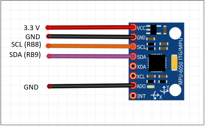
Figure 2: IMU wiring.
At the start we had trouble establishing an I2C connection and receiving data from the IMU. The problem was caused by faulty connections to the bread board. Our solution was to solder the IMU onto a perforated board. Also RA1 doesn't work on the PIC32 when I2C is being used. The figure shown below shows a screenshot of the data line (top) and the clock (bottom) of the I2C connection.
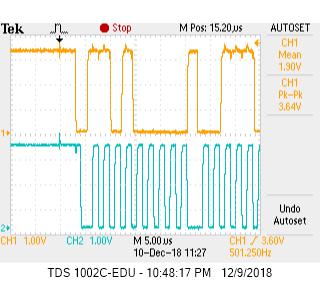
Figure 3: PIC32 and IMU I2C connection on Oscilloscope.
To retrieve data from IMU, we use PIC32 I2C library with the upper level i2c read and write helper functions. IMU is initially in sleep mode, we set the sleep mode to 1 to activate the IMU and IMU will start to store the measurement into the the data register. We use the three gyro values on our drone. Each measurement value is divided into two bytes stored in two registers. We read char type data for lower byte and higher btpe then concatenate them to an 32-bit integer. To get a more accurate gyro data, we sample the gyroscope over an extended period and average it in order to find and substrat the bias.We read the imu inside interrupt service routine to get the gyro rate of the drone and feed it into PID controller to adjust the drone's position.
nRF24L01+ Radio
We predicted that when we tune our PID algorithm, it would serve helpful to have a remote control that would allow us to tune and start the drone remotely. Since we are using the small board on the drone, we thought it will be very helpful to downlink the IMU data as well, so that we can confirm that the IMU's reading and check the PID controls. The following image is a wiring diagram for the radio to the Pic32 (communication was over SPI). The radio that was mounted to the big board, which served as our base station used RB8 and RB9 respectively as CE and CSN, while we changed tho RB3 and RB2 respectively,because we were using RB8 and RB9 for communication for I2C to the IMU.
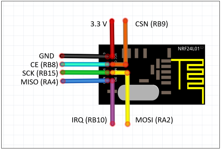
Figure 4: nRF24 wiring (on the small board CE is RB3 and CSN is RB2).
One of the two radios was placed on our base station, which included a PIC32 mounted on a Big Board with the TFT screen, so we can see the downlinked data, as shown in the image below. We also included a 10k potentiometer that was used to choose the desired flight time for the quadcopter to hover for. There is also a switch on the board which will send a start signal to the quadcopter which will signal it to start the PID algorithm and lift off.We mounted the other nRF24 on the drone and used it to transmit IMU data, which was measured in the ISR, during the PID algorithm.
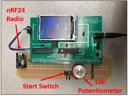
Figure 5: Basestation.
Mechnical Layout
Important considerations for mechanical layout included minimizing weight and balancing the quadcopter so that its center of mass was positioned at the center of the four motors, making attitude control easier. The 3D-printed chassis was designed with simplicity and weight savings in mind. It was sized based on the 3-inch propeller diameter to give ample room for the electronics and battery in the center. The chassis is two-dimensional, meaning that it can also be lasercut instead of 3D-printed. We wanted to keep this option open in case we decided to use acrylic, which is stronger than 3D-printed ABS plastic, or balsa wood, which is lighter. In the end the 3D-printed version worked fine so we didn't change the design.

Figure 6: Preliminary CAD model of quadcopter showing the chassis, motors, propellers, battery and electronics.
Electrical Layout
Most off-the-shelf ESCs take in a servo pulse which consists of a 50Hz PWM signal with 1-2ms pulses. A 1-ms pulse corresponds to minimum throttle (motor does not spin) and a 2ms pulse corresponds to full throttle (maximum motor speed). The ESC converts this servo pulse into PWM signals that it uses to control MOSFETs arranged in a bridge (shown in Figure 7). Each pair of power MOSFETs controls the switching of one phase of the 3-phase brushless DC motor. The DYS F18A ESC we used has four circuits like the one shown in Figure 7, one for each motor. Each circuit accepts an independent PWM signal but all are powered by the same battery.
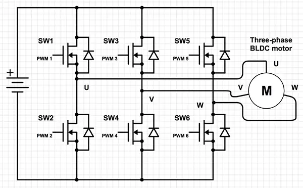
Figure 7: 3-phase brushless DC motor control using MOSFETs, diagram from Digikey .
A secondary function of the ESC is to step the battery voltage down from 7.4V or 11.1V and provide a 5V output. On RC aircraft this is used to power the receiver, but we used it to power the PIC32. Figure 8 shows a schematic of the motor control used in this project.

Figure 8: Motor control using an electronic speed control with a built-in step down voltage converter.
Software Design top
Communication
The software part design is divided into ground station design and the drone control design. The ground station runs on the big board, it has two functions, the first function is to send the command to the drone. There are two commands: start signal which is controled by a toogle switch and hovering time setting, which is controled by the potentiometer. The second function is to receive the telemetry data from drone and display it to users. On the other hand, the drone flight controller includes the PID algorithm that controls the attitude of the drone by changing the PWM of four motors, the radio mode transaction that receive the start information from the ground then send imu back to ground, and the IMU reading part via I2C. drone flight controller is running on the small board.
The radio on the drone starts off at receive mode (RX mode), waiting for the start signal. The start signal contains the flight time which is measured in the number of clock cycles, where each clock cycle is 2 msec. The radio on the base station, starts off in transmit mode, awaiting the user to toggle the switch up. As soon as the switch is toggled, the flight time is transmitted and the base station goes into RX mode, awaiting the IMU data from the drone. Upon receiving the start signal, the drone switches into transmit mode. It downlinks the IMU data as well as the flight time, which are printed on the TFT screen of the basestation. The drone also transmits a known sequence, to the base station to notify when there is a new round of data coming, to ensure that both radios are synchronized.
Motor Control
The quadcopter determined its attitude by integrating gyro data in two axes to get two angle measurements, $$\theta_x$$ and $$\theta_y$$ Both PID control and IMU reading occured in an ISR. After reading the gyro, angle was determined by euler integration:
$$\theta_x = \theta_x + \omega_x dt$$
$$\theta_y = \theta_y + \omega_y dt$$
An initial gyro offset is removed when the IMU is set up by taking two gyro readings 100ms apart and averaging them. This procedure is done only once, in the main loop when the quadcopter is sitting still on the ground prior to takeoff.
We employed several methods to compensate for gyro drift. First, we reset the angle reading whenever the gyro data changes sign. Second, a complementary filter uses accelerometer data to correct the gyro readings. 98% of the angle reading comes from the previously mentioned gyro data integration and 2% comes from accelerometer determination of attitude in relation to the direction of gravitational acceleration.
$$\theta_{x,acc} = tan^{-1}(\frac{\alpha_z}{\alpha_y}) \frac{180}{\pi}$$
$$\theta_{y,acc} = tan^{-1}(\frac{\alpha_z}{\alpha_x}) \frac{180}{\pi}$$
$$\theta_x = 0.98 (theta_x + \omega_x dt) + 0.02 theta_{x,acc}$$
$$\theta_y = 0.98 (theta_y + \omega_y dt) + 0.02 theta_{y,acc}$$
As these equations show, rotating around the x-axis results in a vector along the y-axis and rotating around the y-axis results in a vector along the x-axis. The complementary filter uses the more accurate gyro readings to produce angle measurements that are accurate in the short term, but uses the accelerometer readings which do not drift to measure the angle in the long term.
Two PID controllers run independently, one for x-axis rotation and one for y-axis rotation. Both controllers work to maintain the angle of the quadcopter at takeoff. The initial angle is taken as $$\theta_x = 0 $$ and during the flight the controller tries to drive the angle back to zero. Figure 9 shows a block diagram of the PID control for each axis.
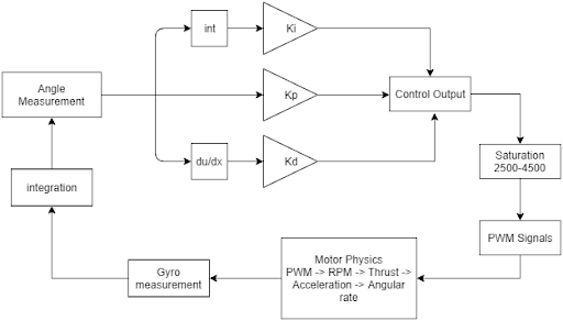
Figure 9: Block diagram for single-axis PID control.
The control signal for each axis is generated as shown in Figure 9:
$$M_x = K_P theta_x + K_d \omega_x + K_I (int_x + theta_x dt)$$
$$M_y = K_P theta_y + K_d \omega_y + K_I (int_y + theta_y dt)$$
We converted control signalst to PWM signals by assigning two motors to each axis and increasing or decreasing their PWM signals in proportion to the control signal on that axis:
$$PWM_{X+} = 2500 + M_0 + M_x$$
$$PWM_{X-} = 2500 + M_0 - M_x$$
$$PWM_{Y+} = 2500 + M_0 + M_y$$
$$PWM_{Y-} = 2500 + M_0 - M_y$$
In these equations M0 denotes a setpoint where the motors should stay if the quadcopter is close to an angle of zero. This setpoint should be high enough so that the quadcopter can still lift off if all the motors run at that speed. We ramp the setpoint up and then down again at takeoff and landing to make flight smoother and to prevent noise spikes associated with rapid motor acceleration. The setpoint starts at zero and ramps up to 1500 during flight. Limiting the PWM signals to the range 2500-4500 cycles (1ms servo pulse to 1.8ms pulse) there is a 1500 cycle range on each side of the setpoint for the PID controller to work with.
Results top
Performance
The PIC32 has the ability to control a motor with an ESC. We borrowed an ESC, and motor of similar type to the one we hoped to use on the quadcopter and compared the performance we got from sending a PWM signal from the PIC32 versus plugging the ESC into a model airplane receiver and throttling up a controller. Initially the ESC would not respond to the servo pulse generated by the PIC32 because we had set the low threshold at a 0.8ms pulse to ensure that the motor didn't spin when we turned the PIC32 on. As it turns out, the ESC needs at least a 1ms pulse to recognize that it is receiving a signal, at which point it will turn on and detect that a motor is connected. Another issue with jittery motors and inconsistent motor speeds turned out to be due to the trimpot we were using to control the width of the servo pulse. The pot was jumpy and would cause the pulse to change unpredictably.
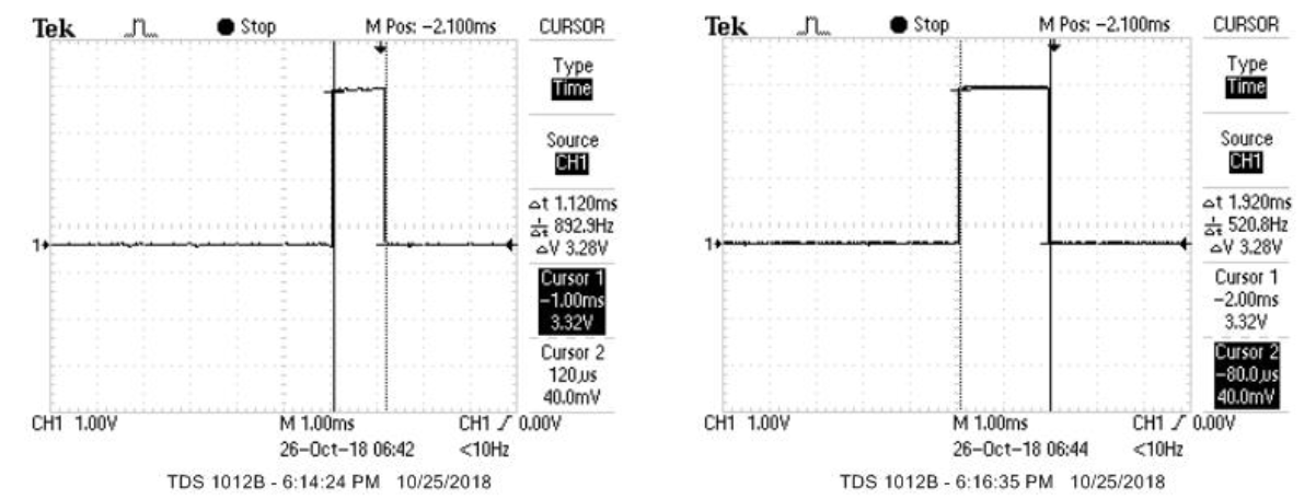
Figure 10: Low (left) and high (right) servo pulses measured from a model airplane receiver and replicated with PIC32 PWM.
After verifying that we could control a motor with PWM, we bought some motors and a 4-in-1 ESC. Bad wiring and loose solder connections led to a lot of debugging once we had the ESC and motors connected. Figure 11 shows a test setup using a model airplane receiver to test the motors and ensure that the connections were stable. The ESC we bought had several undocumented features that led to further debugging. If the ESC powered on and immediately received a servo pulse greater than 1ms in width it would not power the motors, presumably to protect against someone turning on their aircraft with the throttle stick high. Additionally, power cycling the ESC while the throttle is high causes it to enter "calibration mode" which precipitates all sorts of unexpected behavior, including motors spinning slower than usual. Re-calibrating all motors at the same time by power cycling the ESC at high throttle with all motors attached, then bringing throttle to zero and waiting for the ESC to respond fixed this issue whenever it occured.
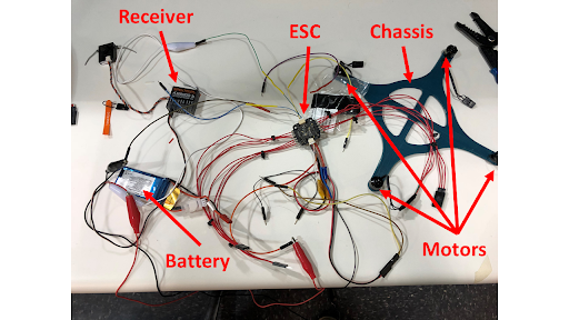
Figure 11: Motor and ESC test setup
While testing without the opto-isolators we found that high motor speeds or fast motor acceleration created noise spikes that caused the PIC32 to reset. To prevent this, we limited the servo pulse to 1.8ms max (90%) of max motor speed and ramped the PWM setpoint slowly ( < 10 PWM cycles per ISR cycle). This problem still poses a serious limitation to the design, since a disturbance torque caused for example by wind could cause the PID controller to request a large change in motor speed and reset the PIC32. A more robust design would either power the PIC32 from a separate battery and reintroduce the opto-isolator circuits, or buy a better ESC with its battery ground isolated from the 5V out ground and signal ground.
For the first stage of PID control testing and tuning we powered two motors at a time and controlled just one axis of rotation. We held the quadcopter steady along one axis and displaced it from horizontal to observe how well it recovered. Initially we had trouble integrating the gyro data and stabilizing the quadcopter due to the low frequency of the servo pulse control (50Hz). We increased the frequency to 500Hz even though the ESC was only rated for 50Hz, and although the threshold for motors turning on decreased slightly and motor speed overall increased, we saw no significant adverse effects. 500Hz is the maximum frequency because a 2ms servo pulse must have a period greater than 2ms. We used 1.8ms as our max pulse width so 500Hz worked fine.
Video 1: Quadcopter flight with PID control running at 50 Hz
After the control frequency increased to 500Hz the quadcopter was able to successfully integrate gyro data to obtain angle measurements and control its angle at a high enough bandwidth to fly reasonably level
Video 2: Quadcopter flying with PID control running at 500 Hz
We chose our initial PID controller gains so that for each axis at an angle of about 30 degrees off horizontal the servo pulse on one motor would be at max (1.8ms) and the servo pulse on the other motor would be at minimum (1ms). We observed the width of the servo pulses on an oscilloscope without the motors connected and tilted the quadcopter to find these gains. This initial estimate proved to be much too high gain, especially proportional gain. Before flight testing, we hung the quadcopter from a string and connected two motors with a lower battery voltage so they would balance the quadcopter but not cause it to take flight. This turned out to not be the best method of testing since the string occasionally got tangled up in the propellers, but it allowed us to see that the best strategy was to use quite low gains (Kp = 10, Kd = 50, Ki = 0.04).
Video 3: Quadcopter flight with tuned PID control and gyro drift compensation
Test Flight Results for Various Gainsets
| Controller Gains and Filtering | Results of flight |
|---|---|
| Kp = 1, Kd = 5, Ki = 0 | ~10 ft travel from takeoff point |
| Kp = 10, Kd = 5, Ki = 0 | Flipped over and crashed |
| Kp = 10, Kd = 500, Ki = 0 | Flipped over and crashed |
| Kp = 10, Kd = 50, Ki = 0 | ~7ft travel from takeoff point |
| Kp = 10, Kd = 50, Ki = 0.1 | Flipped over and crashed |
| Kp = 10, Kd = 50, Ki = 0.04 | ~5ft travel from takeoff point |
| Kp = 10, Kd = 50, Ki = 0.04 and complementary filter | ~ 2ft travel from takeoff point |
We also attempted to control the altitude of the quadcopter but integrating the accelerometer data twice proved to be very unstable, and altitude readings were inconsistent. The position readings drifted so severely that the quadcopter could not tell whether it was at the correct altitude. Additionally, adding these integration calculations as well as the third PID controller to the ISR prevented us from sending radio transmissions because the ISR took such a long time that there was hardly any CPU time to do other things like send transmissions.
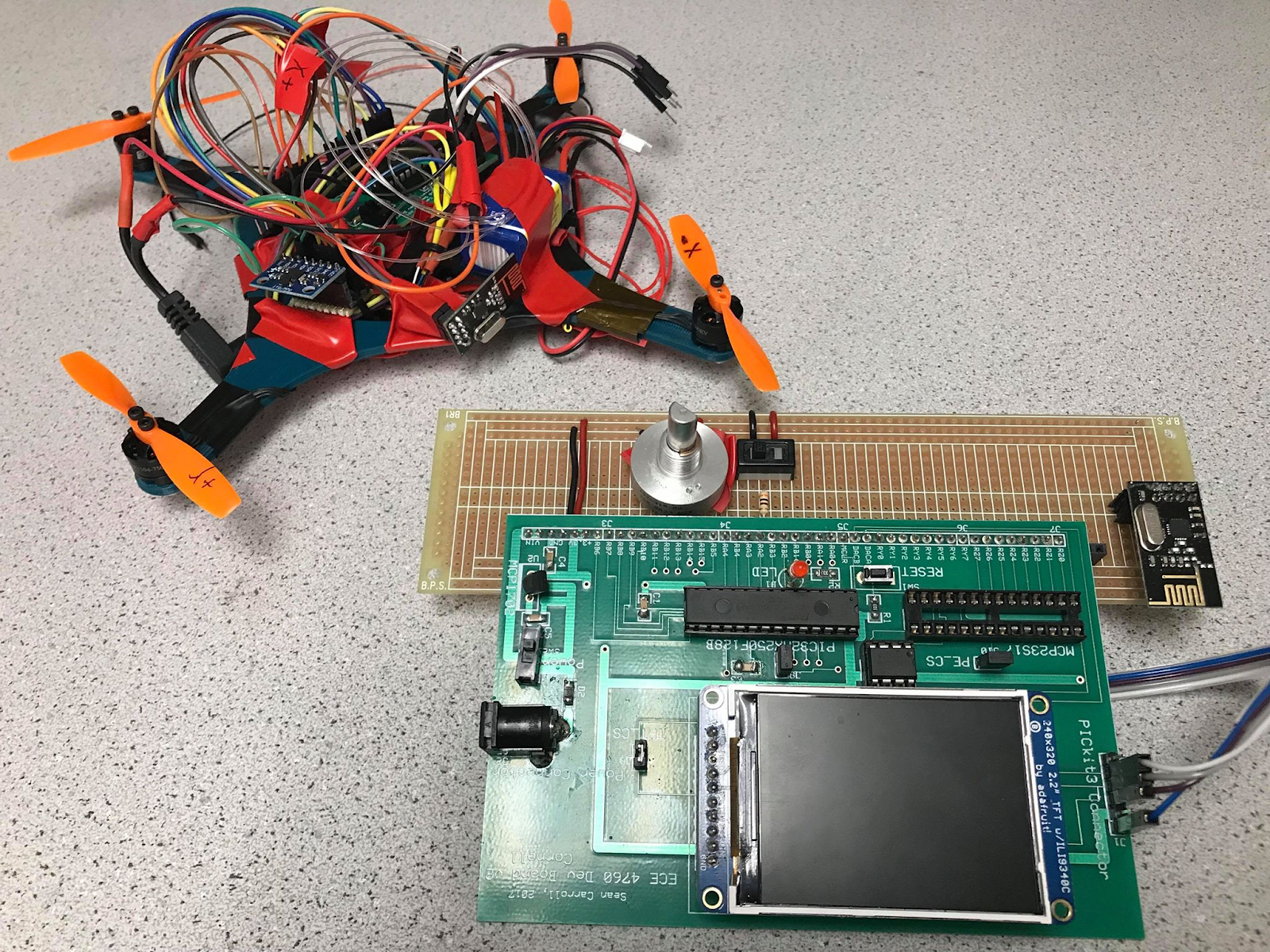
Figure 12: Fully constructed quadcopter and controller
Principles
We ensure the safety of our design during the whole development process. The drone is wired with a string to constrain its mobility during the test and the battery state is stricly under supervised. We control the flight time such that the drone will land in the certain range of region. We use RF radio since there might be interference with other RF device. As the radio we use has a relative small range, the interference can be limited by increase the distance between drone system and other noise source. We also try to increase the usability through our design. We create the ground station so that user can trigger the drone remotely with a switch and be able to control the hover time using the potentiometer.
Conclusion top
Evaluation
Originally we had hoped to create a quadcopter capable of autonomously hovering for some length of time. In the end we were not able to get the quadcopter to hold a certain altitude, but we did manage to stabilize attitude to a reasonable extent so that it could fly for short hops without skittering across the floor. The gyro integration worked better than we expected it to, and with an IMU as our only sensor we think we were able to get reasonable performance out of the quadcopter. Radio transmission and control also worked quite well.
Future Improvements
With another sensor such as a linear distance sensor or a barometer to measure altitude this quadcopter could accomplish the goal of autonomous hovering without too much trouble. Some changes to the software would be required to make the ISR run faster. Currently, too much floating point arithmetic is used. We should have done everything in fixed point or integers and eliminated divides by precomputing some things and using more bit shifts. We also experimented with faster ways of sending radio transmissions which would increase our data rate. This would be helpful for debugging, and with a serial connection to the controller we would be able to plot IMU data from the flight. Currently data is received slowly and our test flights are short, so not much useful information is returned. On the mechanical side, propeller guards would have made testing easier and reduced damage to the quadcopter. We opted for small propellers because we didn't want to spend time building propeller guards, but it would have been a small time investment for a large gain in ease of testing.
Intellectual Considerations
This project is a system that demoed the possibility to use pic32 to control the drone by running the ground side and the drone side on two pic32 board. We also extend PID algorith from a single motor control in lab4 to the four motor control and have the physical interaction and communication system. We used the imu code from the last year project as listed in appendix.
Safety Considerations
The main safety concerns applicable to this project involve the drone hitting things and people, especially with unguarded propellers. Propeller guards would mitigate this risk and are recommended for future designs.
Legal Considerations
The radios used in this project transmit at 2.4GHz which according to Part 15 of the FCC rules restricts them to 1 watt transmission power, which the radios do not exceed as per their specs. The Federal Aviation Administration (FAA) rules for small unmanned aircraft (UAS) operations other than model aircraft. The drone weighs less than 55 lbs and the operators are all over age 16, which meet the FAA regulation.
Appendices top
Appendix A:
The group approves this report for inclusion on the course website.
The group approves the video for inclusion on the course youtube channel.
Appendix B: Budget
| Item | Unit Cost | Quantity | Total Cost |
|---|---|---|---|
| DYS BE1104 Motor | $10.50 | 4 | $42.00 |
| 11V battery | $9.99 | 1 | $9.99 |
| Propeller Set | $1.00 | 1 packet of 4 | $1.00 |
| ESC | $34.99 | 1 | $34.99 |
| MPU-6050 IMU | $9.34 | 1 | $9.34 |
| nRF24L01+ Radio | $0.75 | 2 | $1.50 |
| 10k Potentiometer | $1.00 | 1 | $1.00 |
| Big Board | $10.00 | 1 | $10.00 |
| SmallBoard | $4.00 | 1 | $4.00 |
| PIC32MX250F128B | $5.00 | 2 | $10.00 |
| Jumper Cables | $0.10 | 16 | $1.60 |
| Solder board (6-inch) | $2.50 | 1 | $2.50 |
| Total: | $127.92 |
Appendix C: Schematics
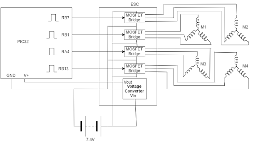
Figure 13: Motor control
Appendix D: Source Code
- final_project The project file
- Basestation_Lab5.c The basestation code
- Drone_Lab5.c The drone code
Appendix E: Division of Labor
| Stewart Aslan | Thinesiya Krishnathasan | Yijia Chen |
|---|---|---|
| PID controller | Integration of the nRF24 | Ground station |
| Motor control | Integration and testing of the IMU | Soldered the circuit components and assembled the circuit |
| Mechanical design | software integration of pic and radio | Test of the nRF24 |
References top
This section provides links to external reference documents, code, and websites used throughout the project.
Datasheets
- MPU 6050 Description
- Pic32 Microcontroller
- MPU 6050 IMU Datasheet
- MPU 6050 IMU Register Maps and Descriptions
References
Backround site
Acknowledgements top
Thank you Professor Bruce Land for all the guidance through this semester. We would also like to give a huge thanks to each of our TAs for the support. We are greatful that you guys took the time and and had the patients to answer all out questions.
We encourage anyone who is looking for a fun and worth-while class to definitely take ECE 4760!