| |
The hardware used for this project include:
- STK200 programming board
- ATmega163 MCU chip
- Hyundai (model HG25504NG-01) 256x128 LCD display
- Analog Device ADXL202EX accelerometer
- Speaker (small one from cricket call lab)
|
|
| |
STK200 Programming Board
& ATmega163 MCU |
|
| |
|
|
|
Hyundai 256x128 LCD
|
|
|
|
- We purchased a 256x128 LCD
from All Electronics Corp.
(CAT# LCD-58). We chose that particular LCD because it uses the
SED1330F display controller. This is the same controller as
the one in all of the LCDs that were used for last year's final
projects (Spring 2001). We felt that the reports of those projects
could provide additional help in case the documentation of the LCD
was not enough.
- The LCD display was used to display
the hourglass and sand. The documentation was complete and provided us all
the details we needed to hook up the LCD to the board. The LCD required a
-24 V power supply and a potentiometer for adjusting contrast. At times,
the connection of the potentiometer to the breadboard would not be good
enough for the LCD to display properly. We then soldered wires to the
potentiometer and this worked a little better.
- Since LCDs with the SED1330F
display controller was used extensively for last year final
projects, it wasn't difficult to obtain usable code to output
something on the screen. Here is the basic methodology in
controlling the LCD, for anyone who is trying to use this LCD, but
has no idea what the C-code means. Of the 17 pins on this Hyundai model,
aside from the normal supply pins and display contrast pin, there
are 8 data pins and 5 control pins. Whenever the user wants
to talk to the LCD, he needs to send the "content" as an
8-bit word to the data pins, and force the LCD to accept it by
adjusting the control pins (such as toggling the NOT write pin, /WR).
Now there are two types of "content" words that the user
can send, one being command codes and the other data codes. The
status of the control pins tell the LCD whether the
"content" sent on the data pins constitute a command
code or data code. There are many command codes (refer to
documentation for listing), each particular one puts the LCD in a
particular mode, such as the system set mode, or the writing mode,
etc. For example, if
the user wishes to write the letter "A" on the screen,
here are the steps (NOT CODE):
- Send command code for writing character on screen on data pins
- Put LCD in character display mode by forcing it to accept
that command code using control pins
- Send data code ("A") on data pins
- Tell LCD to intepret word on data pins as data code through control pins
So from the above steps, it would be correct to say that the
LCD stays in one mode until it accepts another command code. Note
that as written on the documentation, certain modes can accept
more than one data code, and the controller expects particular
sequences of data code. So it wouldn't be wise to send a
command code every time before a data code is passed in.
- We were pleased to have
found a program on Mike Rankin's website to test our
LCD. It proved to be invaluable for this project.
|
|
Analog Devices ADX202EX
|
|
| |
- We were able to obtain free samples of Analog Devices'
ADX202EX accelerometer. The chip did not come in a DIP package, so
Professor Land helped us solder the accelerometer onto one of his circuit boards
to make it more accessible.
- As described in the data
sheet, ADXL202EX outputs both duty cycle modulated signals (DCM)
and DC voltage, either of which alone is enough to gather the tilt
angle. Since the circuit board Professor Land provided us only
wired out the voltage outputs, we used that to get the tilt angle.
The accelerometer outputs different voltages for each of the different positions that it is
in (0 to 180 degrees).
The raw output voltage range for our particular chip was between 2.15 and
2.7V, approximately.
- We felt that the approximate 500mV
range was enough to implement a 180-degree range because the A/D
converter has a resolution of about 10mV ((1/256)*Aref, where Aref
is about 2.4V). It also didn't seem necessary to implement
the range in steps of 1 degree. Although the upper limit of the
raw voltage range from the accelerometer is higher than Aref, we
simply resistor-divide the output down to a range that is
acceptable to the A/D converter.
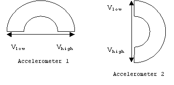
- In order to implement the
whole 360-degree range, it was necessary to use two
accelerometers. We put one accelerometer perpendicular to
the other on the same plane, like the following diagram:

- If we assume that the plane is
oriented with 0 degree on the left, then as the diagram above suggests,
when the voltages from both accelerometers are small, the tilt angle should be
between 0 and 90 degrees. When both voltages are large, it should be
between 180 and 270 degrees, etc.
- The voltages enter an A/D converter. To use the on-board A/D converter, we had to measure Aref each
time, since it is unique for each individual board. Aref is the
maximum voltage that the A/D can convert. Please refer to
the software section for more details.
|
|
Speaker
|
|
|
|
- We used the speaker from the
one of the lab assignments of the course (cricket call generator
lab). It is a tiny speaker that has no built-in amplifier. Hence
we simply connected the output signal from the board to one of the
pins, and connected one of the supply rails (Gnd or Vdd) to the
other. Because of a shortage of ports, we put the speaker onto PORTD, which is also used for the buttons. We had to just be careful when setting
the input and output bits of PORTD.
|
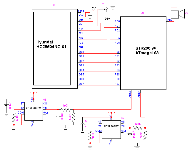
 Schematic of hardware setup
|
|