
|
|
Results
We had several obstacles to overcome to achieve our final result. First, and
most important, was our problem with the detector circuit. The photo transistors
we used were extremely sensitive to light for a broad spectrum of wavelengths.
Normal ambient room light (even if dimmed), would drive the transistors to within
about 200 mV of ground (since they were logic low). Shining a laser at them
produced very little difference in output voltage, and certainly not enough
to detect accurately. Also, a change in light close to the detector (e.g. waving
your hand in front of the detector) caused large swings in voltage, large enough,
in fact to completely mask any changes caused by the laser. This rendered the
detector in this form almost completely useless. Since no amount of circuitry
could make the transistor detect only red laser light, we had to pursue other
options. The only viable option was to find a red light filter with a very narrow
wavelength transmission bandwidth, and correspondingly accurate lasers. Since
our cheap laser pointers had a large range of possible wavelengths (630-680
nm), we bought some higher quality laser module with wavelengths of 650 nm +
or - 5. We also purchased some high quality glass laser light filters to block
most of the ambient light. With this combination we were able to get rid of
99% of the ambient light (normal bright room lighting), and still detect accurately
fired laser pulses. Now, we can detect laser pulses from various ranges (since
the laser attenuation through air is virtually nill) when the laser is fired
at a 90 degree angle to the inch diameter filter. About 99% of these pulses
get detected. But as you move at an angle in direction from the filter the accuracy
decreases rapidly due to a two-fold problem. First, the filter is highly reflective
at angles above 30 degrees, and second, the transistors can only detect over
a 50 degree cone. Also, since the filter is only 1 inch in diameter, the player
needs to fire very accurately to hit the detector. This is not a huge problem,
though, since this is Sniper Tag, and we wanted to require high accuracy.
The second problem we encountered was a communication issue. Since the receiver
is very accurate it automatically locks on to the largest (peak to peak) signal
it can find. If that signal is not the normal 5 volt peak-to-peak signal, it
will grab some noise which may or may not be large. In our case, it would grab
a 4 volt signal regardless of our efforts to minimize surrounding noise, or
build better antennas. We solved this problem by always transmitting a signal
at 1 kHz. The receiver now worked correctly, and picked up our “hit”
signal, which was previously drowned out by noise. Unfortunately, the receiver
also picks up the strongest signal, which, in the case of the circuit which
produced the continuous signal, meant that the other more important message
from the opponent’s transmitter was drowned out. This is not a huge issue,
since one of the LCDs is correctly synced and hits are still detected, but sometimes
this player would not know (except for the noise) if he hit the opponent. This
problem could easily be fixed by making the system full duplex by replacing
one transmitter and receiver (on opposite player circuits) with the ones that
run at 418 Mhz. This is something that is also discussed further in the improvements
section.
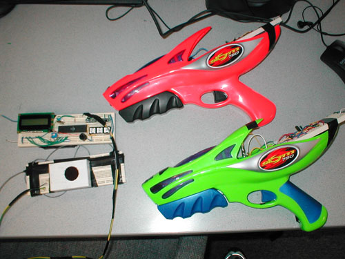
Overall, the project was a definite success, since we had two working detectors
and laser guns. Our goals for an accurate visible laser tag system have been
met. On top of this, we both have learned an enormous amount about building
practical, but cheap projects, while having a lot of fun shooting each other
with lasers.
 |