Cornell Hockey
ECE 476 Final Project
Rives Borland
Ryan John
Brian Tarricone
news | intro | hardware design | software design | other considerations | code | results | next time
Hardware Design
The heart of the game is an Atmel AtMega32 microcontroller, running at 16MHz. The MCU has four I/O ports. Two of the ports (B and C) are used for input from the Sega Genesis controllers. Port D serves to output both the NTSC video and sound signals. Port A remains unused.
 The NTSC video signal is sent to the TV via a simple two-bit digital to analog
converter. Simple black and white TV requires three voltage levels: 0V for
sync generation, 0.3V for black, and 1V for white. To generate these values,
all we need are three resistors: 300, 75, and 1k Ohm will generate the three
voltages we need.
The NTSC video signal is sent to the TV via a simple two-bit digital to analog
converter. Simple black and white TV requires three voltage levels: 0V for
sync generation, 0.3V for black, and 1V for white. To generate these values,
all we need are three resistors: 300, 75, and 1k Ohm will generate the three
voltages we need.
The Sega Genesis controllers use an industry-standard 9-pin DB9 plug. This made hookup to the MCU easier, as we could just pick up a DB9 connector from Radio Shack. We originally were considering using controllers from the original 8-bit Nintendo, but they used a proprietary connector (plus a slightly more complex data protocol). The Sega Genesis controller has a relatively simple data protocol. One pin each is used for power and ground. One pin is a MUX select line, and the remaining six pins carry button data. There are eight buttons on the controller, and the state of the MUX line selects which buttons affect the six data lines. Reading the buttons is a two-step process. First we set the select signal low, and read the data pins. We shift the values up into the top of a 'char' variable, and then set the MUX select high. We again read the data pins, overwriting the lower bits of the 'char' variable. We carefully select the read order to allow us to fit all eight buttons into an 8-bit variable without having to slide the bits around too much. The button pushes are active-low, which makes it difficult logic-wise to detect multiple button presses. To make it easier, we bitwise-complement the button state variable so a '1' indicates a button push and a '0' indicates no button push. This way we can test for multiple button pushes easily using bitwise AND.
 The sound hardware is simple - just a one-bit on/off square wave. The output is
from a single port pin, taken across a 15kOhm resistor. This allows us to
generate simple tones at any pitch we specify. We "arranged" both 'Davy,'
Cornell's fight song, and Cornell's Alma Mater to play during the game, as well
as other traditional Cornell Hockey cheers.
The sound hardware is simple - just a one-bit on/off square wave. The output is
from a single port pin, taken across a 15kOhm resistor. This allows us to
generate simple tones at any pitch we specify. We "arranged" both 'Davy,'
Cornell's fight song, and Cornell's Alma Mater to play during the game, as well
as other traditional Cornell Hockey cheers.
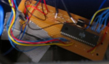
All of this is put together and soldered onto a small circuit board. The board can accept four AA batteries for power, or the output of most any AC->DC transformer. There is an on/off switch and a reset button, as well as two ports for Sega Genesis controllers and two RCA output plugs for video and sound. We made a small enclosure for the assembly, so the entire setup looks vaguely similar to a miniature home gaming system.