The variability of a college student’s class and school work schedule gives way to an abnormal sleep/wake pattern that is not experienced any other age group. Few lucky students have the pleasure of having all their classes start at the same time every day. However, most students do not have this luxury. This requires that most students reset their alarm clocks every night in to adjust to each day’s different schedule. Forgetting to reset the clock could result in sleeping through classes, or unexpected wake-ups hours before classes start. This abnormal schedule disrupts your circadian rhythm and makes it increasingly difficult to get out of bed in the morning. For some it leads to snoozing your way through morning classes.
We have created a new type of alarm clock that will have a built in record of your weekly schedule so that it may wake you up at the right time, every time, every day. Our alarm clock will includes extra features that improve on the shortcommings of current alarm clock designs.
Features Introduction
Even chronic snoozers will have no excuse for sleeping through another class again. Each of the daily alarms will include a feature that indicates a priority for the wake up time. For example, a student may give waking up on Monday morning for class a high priority, while giving waking up for a Saturday morning jog a low priority.
The different priorities will determine how hard it is to disable the alarm. High priority alarms will be louder and annoyingly difficult to reset. This will ensure that the user is well awake before the alarm can be silenced. In contrast, a low priority alarm can be snoozed or disabled with the single press of a button.
The backlight LCD display will inform the user of the day of the week and the date. It will also display the next upcoming alarm to the user. The calendar feature of the clock automatically compensates for leap years. The alarm also features a ambient light controller that will make sure that the seven segment LED display is always an appropriate brightness.
The need for our project was realized after our arrival to Cornell. The rigorous academic schedule of student coupled with the numerous extracurricular activities that most students partake in gives way to a very unnatural sleep schedule. Current alarm clocks are limited to 1 or 2 alarms and do not adjust the alarm according to the day of the week. Forgetting to reset an alarm for the next day may make you miss the next day’s class. Few, if any, reasonably priced alarm clocks have the function to include a weekly schedule. Many people have chosen to use their cell phones as an alarm clock to mitigate this problem. However, it requires that you leave the phone on overnight thus draining the battery or requires you to keep it plugged in overnight. Both of these options are far less than ideal. A standalone alarm clock will relieve these issues while also serving as a time display while you are in bed. Since we have also found that most alarm clocks are annoyingly bright at night, we have included an ambient light sensor that will dynamically adjust the seven segment brightness according to light conditions in the room.
Structure and Rationale
The project was broken into several parts to streamline the development process. Each component was then broken down further into hardware and software components. The three components of the project are Timing, User Input and Display.
Timing
The timing circuitry is broken down into two main features hardware and software. A major decision in the project was weather to use a software timing system based on the MCU or to buy a dedicated hardware timing chip. A clock calendar chip was used to accurately keep time for the system. As a test, we created a timer on the MCU with a 1 ms time base. This timer would increment a ‘seconds’ variable every 1000ms. It was found that the clock would skew about a second every 10 min. Compound over time this would quickly lead to large time errors. We chose a simple clock calendar chip for our application. There were complex chips available with over 4 hardware interrupt alarms. However, we decided that a software implementation would be best for our application. It allows for the flexibility of virtually unlimited alarms. It also decreases the hardware overhead necessary by reducing the number of external interrupts. A chip with 7 alarms each with their own external interrupt would take up nearly an entire 8 bit port on the MC
Display
The display function had to serve two uses. One is to constantly display the time; the other is to allow the user to input data to the system. It was decided that the best method for data input would be a LCD but the best method for time display would be the seven segment displays. We decided to implement both in our design and we decided to display the date on the LCD display when a user was not inputting data. To drive the seven segment displays we selected a LED driver that would allow for easy control of the brightness. Due to budget constraints we selected a LED driver that was already available on the FSAE project team. Two LED drivers were borrowed for this project. The 7 segment displays were also borrowed from the FSAE project team. These 7 segment displays are ultra-bright and allow for a wider range of dimming possibilities.
User Input
We wanted to make sure that setting the time for the device was simple and intuitive. We were originally debating over two input methods. A simple interface with 4 navigation buttons or the use of a large keypad for data input. The added features such as the 7 day programmable alarms made it essential that data input was easy for the user.
It has buttons for incrementing and decrementing a value, a back button and an enter button. The keypad represents a 4x4 grid of buttons for user input. We ultimately decided that the navigational keypad would not only simplify the user experience when inputting data but would also help reduce the complexity of the state machine.
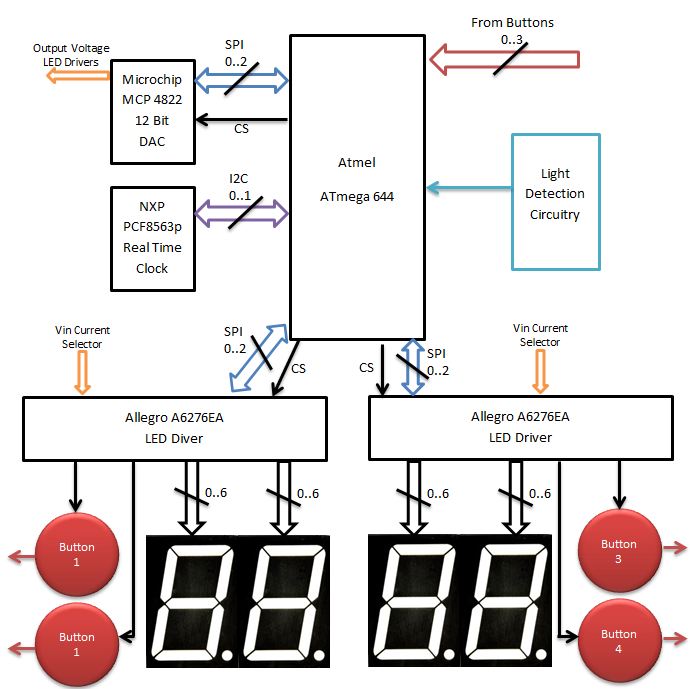
Block Diagram
Click the block diagram to the block diagram below for a better look at the hardware flow
Standards
Communication between chips takes place using two standardized communication protocols. The first of which is SPI interface. This is used by both the LED drivers and the digital to analog converter. We wrote the software to communicate over SPI to both of the chips. Both of the chips communicate using SPI standard 1. The clock calendar chip uses the I2C interface. To communicate to the clock calendar chip over I2C we used the library created by Peter Fleury. His open source software can be found at the link referenced at the bottom of the page.
Patents and Copyrights
We were only able to find one other standalone programmable alarm clock. Although they seem to be the only unique product with this feature we do not infringe on any of their patents. We were only able to find patents for their user interface and not for their 7 alarm feature. Since the user interface of our clock is vastly different from theirs there are no patent conflicts.
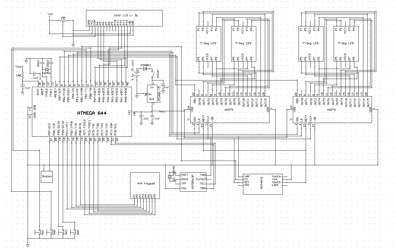
The hardware used in our project is similar to that found in typical alarm clocks. However, because of its expanded feature set some additional hardware was required. Click the image to the right to expand the hardware schematic. See appendix for a download link.
The hardware used in our design includes:
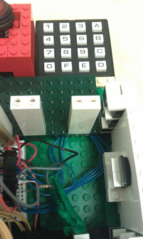
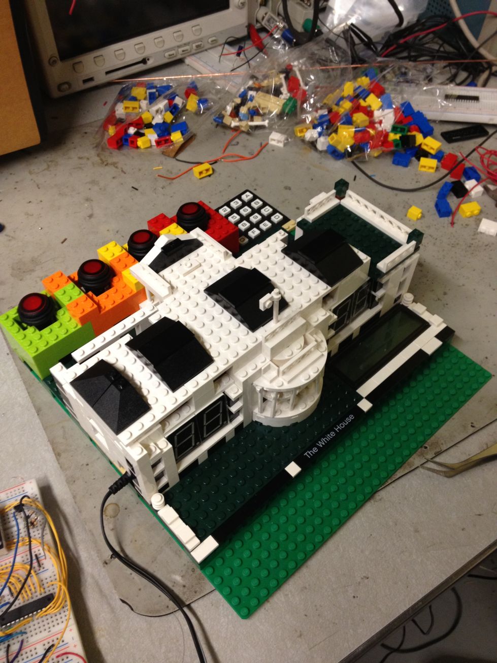
1xKeypad
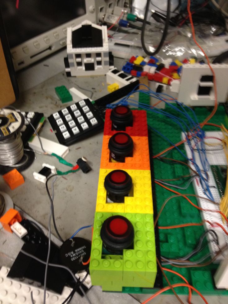
4xIlluminated buttons
1xIlluminated LCD display
4xSeven segment displays
1xClock calendar chip
1xDigital to analog converter
2xLed drivers
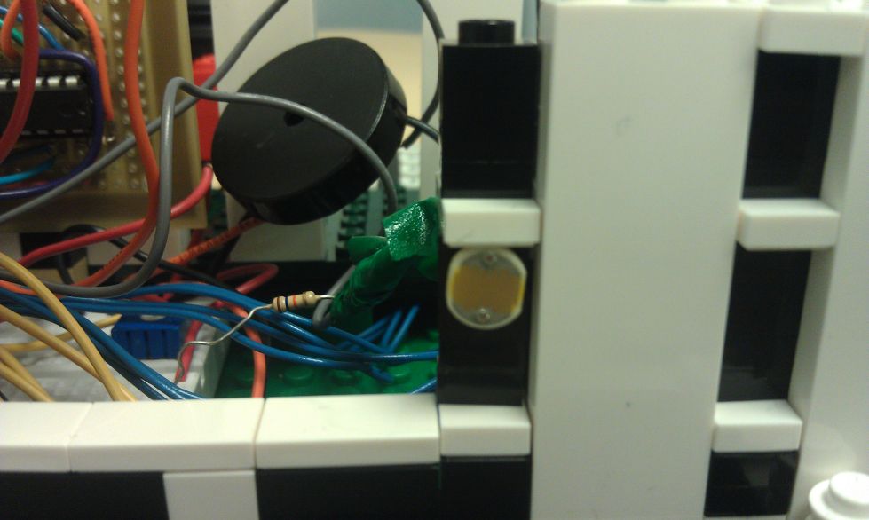
1xPhotoresistor
1xBuzzer
User Input
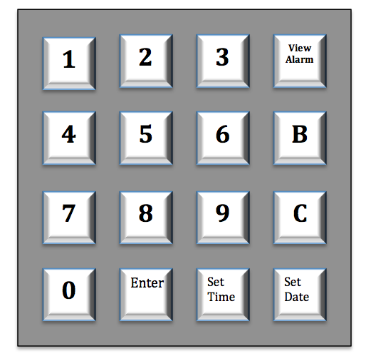
When the clock first turns on the user is prompted to set the time for the clock. The device is unusable until the user sets the time. The keypad is used as the major user input device for time setting. The 4x4 keypad has the numbers 0-9 and the letters a-f. The letters represent various functions of the clock such as setting the alarm, setting the time and enter. The keypad is plugged into ports d0..d3 and c4..c7. The keypad was split onto two ports because other hardware required the alternate functions of special pins (described in following paragraphs).
Buttons are used to silence the alarm. We have included 4 buttons in the design in order to complicate the process for snoozing the alarm. They illuminate corresponding to the button that needs to be pressed. These four buttons are plugged into port B0..1 and port D4..5.
Time Keeping
Time is kept for the circuit using a real time chip. This chip is more accurate than timing with software and also provides hardware support for calendar functionality. This significantly reduces the amount of code necessary to support timing. The chip is connected to the I2C bus on the 644 (Port C0 and C1). The chip also provides hardware support for leap year functionality which eliminates the necessity to ever reset the date.
Display
The display is critical to the usability of the clock. An illuminated LCD is connected to port A0..2, A4..7 to allow the user to see complex messages. This was used in 4 bit mode to reduce the number of port pins used. A potentiometer was used to adjust the contrast of the display. 7 segment displays are used to display the time on the clock. We decided to forego the decimal point on the display and connected 7 of the 8 ground pins. This, however, still requires more pins that would be available on the 644 (given our other hardware requirements). Connected the seven segment displays to a LED driver (CS port B3 and B4) to simplify their use. Code is written to the LED drivers to indicate the pin that should be grounded. A grounded pin corresponds to an illuminated segment on the display. The buttons also serve as a display to the user. A button will illuminate to indicate that it should be pressed. The button’s internal LED is connected to Vcc and to one of the pins of the LED driver. When the appropriate pin on the driver is grounded, the button will illuminate.
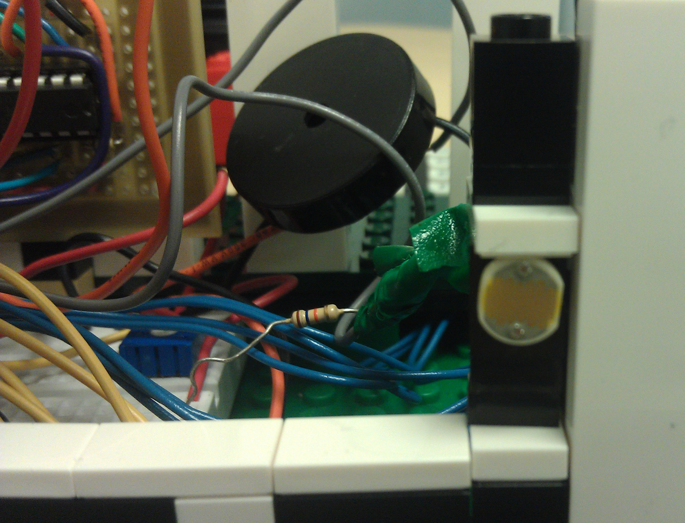
Brightness Control
The ambient light controller consists of a photoresistor circuit along with a digital to analog converter. This circuit is used to control the brightness of the seven segment displays. The output of the photoresistor voltage divider circuit is input into port A3 on the MCU. This port is connected to the ACD and coverts the analog signal to a digital value. The digital value is then compared against a look up table to determine the correct brightness level. The brightness level is converted to a digital value representing a new analog voltage to be output by the DAC(CS port B2). This value is transferred over the SPI interface to the DAC chip. The DAC chip then sends out the correct voltage to the input pin of the LED driver.
Sound Output
Sound is output by the device by controlling the output compare match for timer A. A buzzer is connected to port D7 and the frequency of the output is controlled to create an alarm sound. Depending on the priority of the alarm a different sound will be heard.
Since most of the testing for our alarm clock was conducted in lab, we made sure that the alarm was reasonably quiet. Under real use conditions we would make sure that the alarm was annoyingly loud. We would make use of a powered piezo buzzer to handle the sound output.
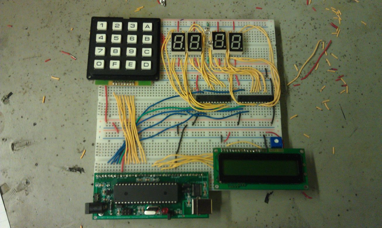
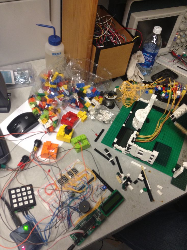
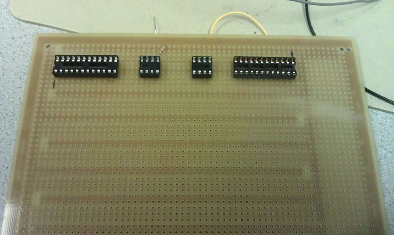
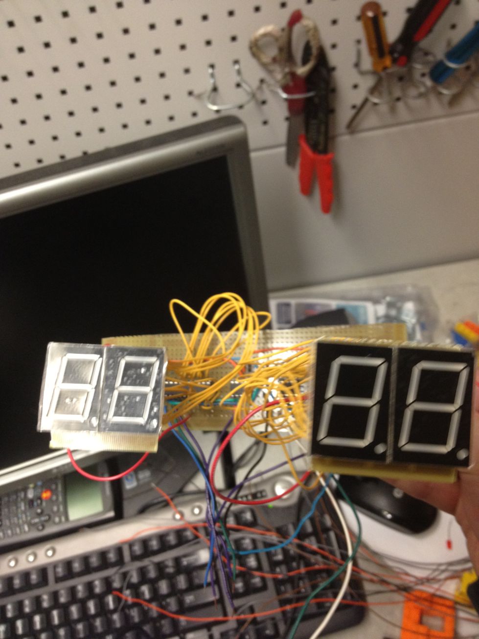
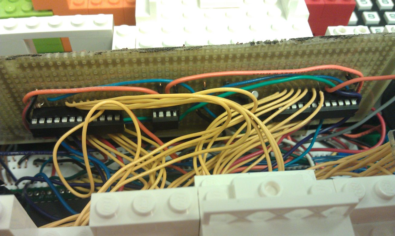
Board Design
The board design was critical to the sucess of our project. Due to the small size constraints of our enclosure it was important to fit all the components in as little space as possible; while simultaneously creating a reliable design. We decided to split the design onto three boards. A whiteboard, a solder board and a seven seg breakout board. This division allowed for the easiest placement of compnonets within the enclosure.
Whiteboard Components:
ATmega 664 dev Board
LCD Contrast Control
Buzzer Control
Photoresistor Voltage Divider
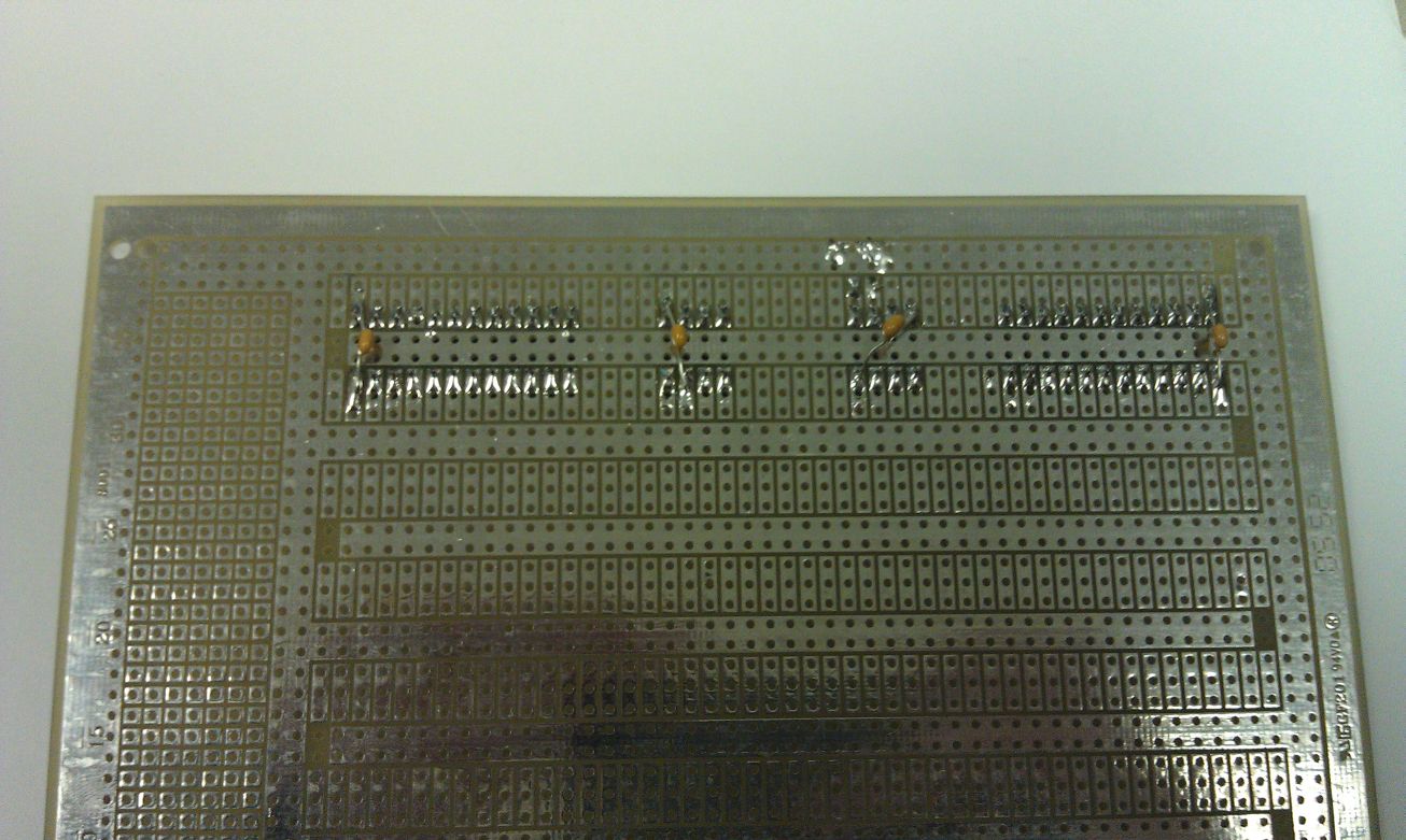
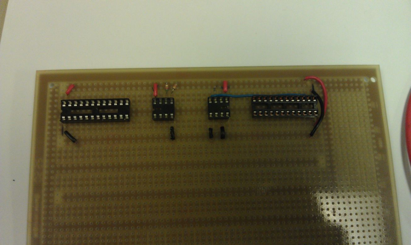
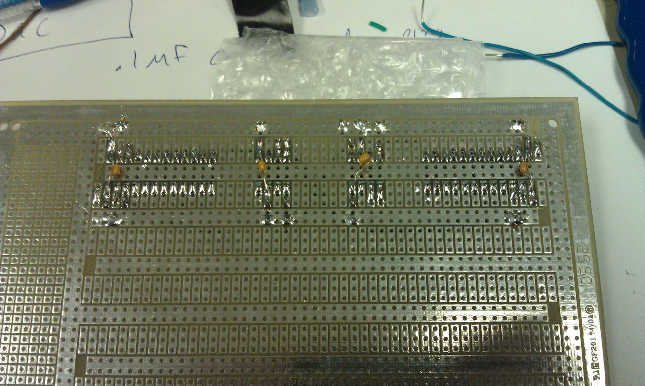
Solder Board Components:
LED Drivers
Real Time Chip
Digital to Analog Converter
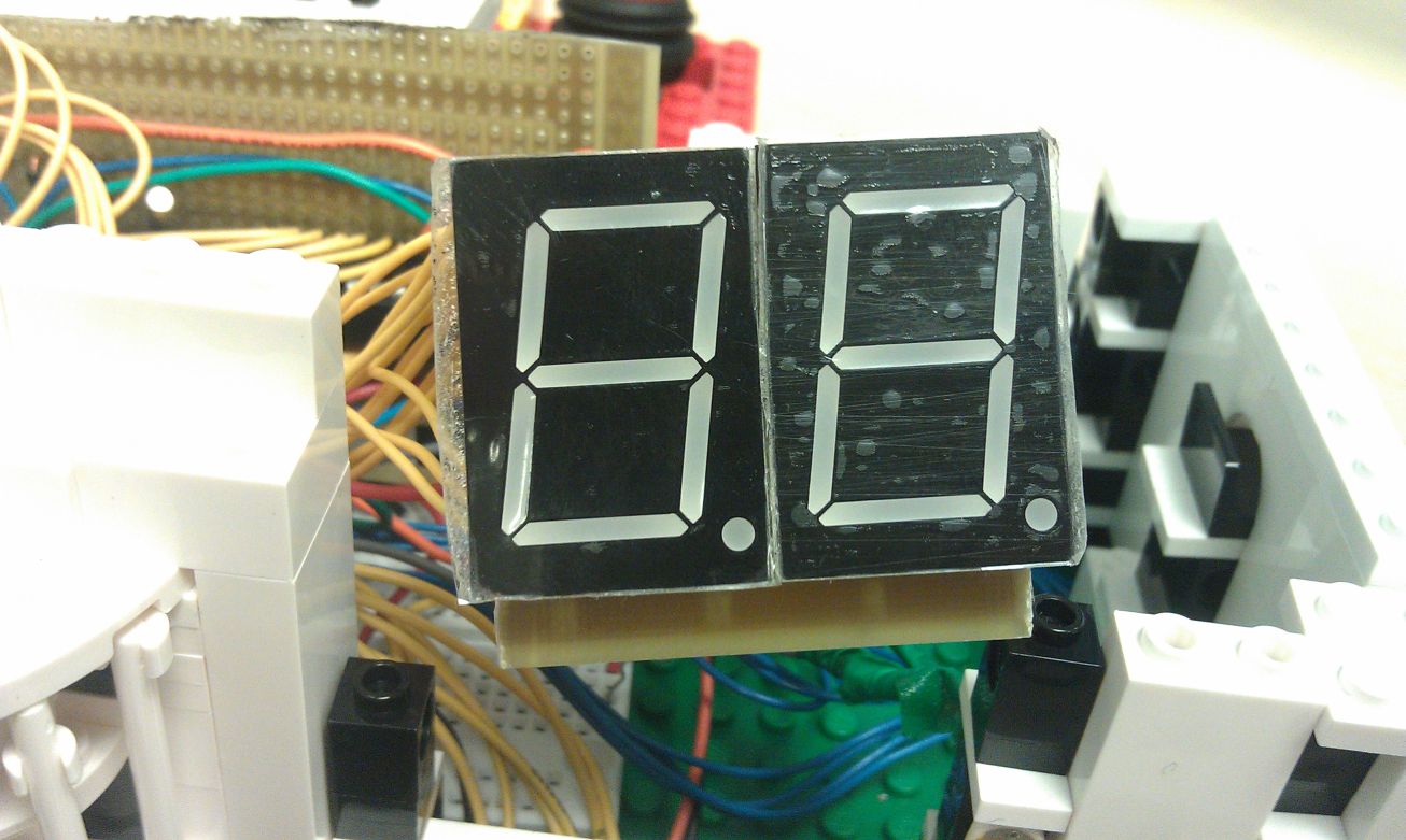
Seven Seg Board Components:
Seven Segment Displays
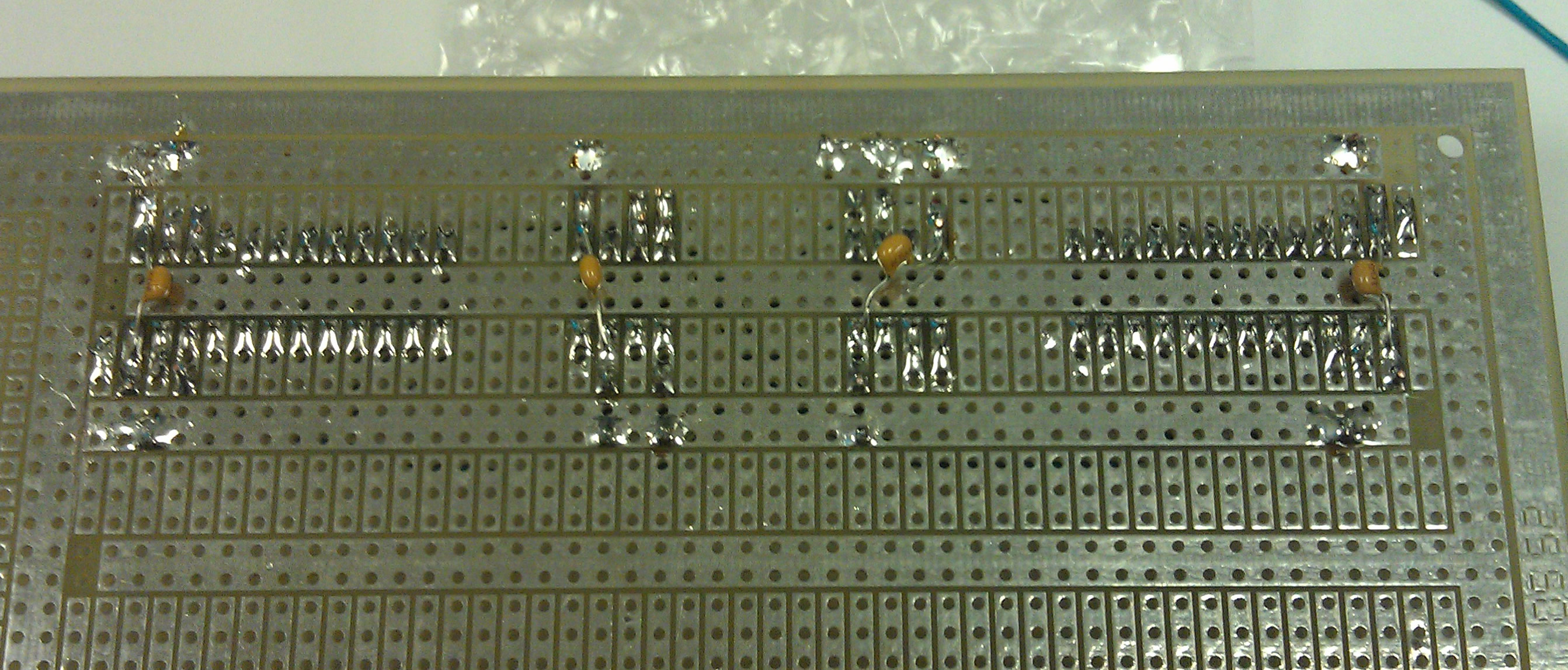
Since our project made use of both very noise sensitive conponents, such as the real time chip, and noisy components, such as the digital to analog converter and led drivers, it was critical that we isolated any possible noise. The board was designed such that a ground plane was placed directly under each of the chips. Each chip then had a decoupling capicator of .1uF connected between its power and ground pins. Without decoupling power and ground it was found that the RTC would count rapidly and randomly.
Software
Program Flow
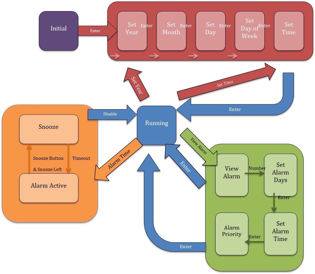
Upon start, the alarm clock will enter the initial state. A welcome message will be displayed on the LCD screen. If the user pushes the enter button, the alarm clock will ask the user to do a series of initial date and time settings. It will first enter the set year state, asking the user to input a two-digit number (00~99) as the year. The value of the current input number will be displayed on the LCD screen. If the user presses the enter button, the alarm clock will enter the set month state, asking the user to input a two-digit number (01~12) as the month. The value of the current input number will be displayed on the LCD screen. If the user presses the enter button, the alarm clock will enter the set day state, asking the user to input a two-digit number (01~31) as the day. The value of the current input number will be displayed on the LCD screen. If the user presses the enter button, the alarm clock will enter the set day of week state, asking the user to input a one-digit number (1~7) as the day of week. A symbol of the current input day of week will be displayed on the LCD screen. If the user presses the enter button, the alarm clock will enter the set time state, asking the user to input a four-digit time in the form of HH:MM in the 24-hour manner. The current input time values will be displayed on the seven-segment LEDs. If the user presses the enter button, all the initial settings will be written to the real time clock and the alarm clock will enter the running state.
In the running state, the alarm clock will read time from the real time clock and update the seven-segment LEDs. Current date and day of week will be displayed on the LCD screen. Date will be updated at the beginning of each day. The user will be able to go back to set the dates and time again by pressing the set date button. Or alternatively the user can set only the time again by pressing the set time button.
The user will be able to set up to 7 different alarms. In running state, if the user presses the view alarm button, the alarm clock will enter the view alarm state. The user will be able to create or edit an alarm by inputting the number of the alarm (0~6). If the user inputs any valid alarm number, the alarm clock will ask the user for a series of inputs to set up the selected alarm. First the alarm clock will enter the set alarm days state, asking the user to specify on which days of a week the alarm is active. The user can input any number between 0~7 representing Sunday to Saturday, and the days selected will be showed on the LCD screen. Multiple days can be selected for one alarm. Selecting the same day twice will cancel the selection. After all the days are selected, the user can press the enter button to enter the set alarm time state. In set alarm time state, the user will input a four-digit number in the form of HH:MM in the 24-hour manner. If the user presses the enter button, the alarm clock will enter the set alarm priority state, where the user needs to input a number between 1~3 as the priority of the alarm. The number 1 represents low priority, 2 represents medium priority and 3 represents high priority. If the user enters a value higher than 3, it will be converted to a number between 1~3 by mod. If the user presses the enter button, the setting of the selected alarm will be done and the alarm clock will go back to the running state.
In running state, the time of the next active alarm of the current day will be displayed on the LCD screen. The program will automatically update the time of the next alarm when there is any change to the alarms or when a new day begins. When the time of the real time clock matches the time of the next alarm, the alarm clock will enter the alarm active state. The buzzer will make periodic sounds, the frequency of which is determined by the priority of the alarm. There will be a “Get Up” message displayed on the LCD screen. If the user presses any of the four snooze buttons, the alarm will be snoozed. The program will enter the snooze state, disabling the buzzer sound and display a snooze message, and start a timeout timer. In snooze state, the user can push any of the four snooze buttons to call the alarm disable function. This function will ask for certain user actions to disable the alarm. The actions are different for different alarm priorities. If the user finishes the required actions before the snooze timeout, the alarm will be disabled and the program will go back to running state. If the user doesn’t disable the alarm before the timeout, the alarm clock will go back to alarm active state, and make the buzzer sound again.
The number of times that the user can snooze an alarm is limited by the alarm priority. For a low priority alarm, the user can snooze up to 3 times, while for a high priority alarm, the user can only snooze once. If there are no snooze opportunities left, the user will need to use the disable function to disable the alarm. If the current alarm is successfully disabled, the alarm clock will go back to running mode and wait for the next alarm. The disabled alarms will still be active after a week.
Data Structures
Date and Time Variables: Date and time of the clock is stored in the following volatile unsigned char variables: sec, min, hr, day, month, year, wkDay.
Date and Time Input: In date and time setting and alarm edit modes, the user inputs will be stored in arrays. Date input is stored in volatile char dateInput[2], and time input is stored in volatile char timeInput[4]. The variables dateDigit and timeDigit serve as the index of the arrays.
Alarm Information: Alarm information is stored in structs: struct Alarm = {int number; char status; char days; int hour; int minute; char priority; } . The days field is a char where the first 7 bits of the char represent the alarm status on the 7 days of a week respectively. Each alarm has its own struct. The seven alarm structs are stored in an array, the length of which is defined by max_alarm.
Display: The messages displayed on the LCD screen are stored as const uint8_t []. The numbers displayed on the seven-segment LEDs are stored as binary coded decimals.
Debounce State Machines
Keypad Debounce: The keypad debounce state machine is a modified version of the keypad debounce state machine from Bruce Land. It is enabled when there is no active alarm. It scans the keypad input every 25ms and look for valid inputs. Pressing more than one keys are pressed at the same time is considered as invalid input and will be ignored by the state machine. A valid keypad push will either change the date and time input array or set a corresponding flag for the state machine. All flags will clear on a key release.
Button Debounce: The push button debounce state machine is modified from the one from Bruce Land. It is enabled only in the alarm active state or the snooze state. It scans the four push buttons every 30ms. Pushing more than one buttons at the same time is a valid input for this state machine. If any of the button push is detected, the snooze flag will be set, and the corresponding digit for the buttons array will be set for the alarm disable function. The snooze flag will clear when all buttons are released.
Time Intervals
There are 5 different time intervals in the program, and they are all generated by timer0. Timer0 is set so that it will be interrupted every milisecond. In the timer0 interrupt handler, the program will first check states and flags logic, and then will check the time counter for each time interval. If the counter is 0 for a specific time interval it will perform certain tasks. Otherwise, it will just decrement the counter.
SPI Communication
SPI communication is needed for displaying time on the four seven-segment LEDs through the LED drivers and controlling the brightness of the LEDs through the Digital-Analog Converter. In our design, the microcontroller is the Master, and the LED drivers and the DAC are the Slaves. The Master only needs to write to the Slaves. To write a value to a Slave, the Master first needs to enable the Slave Select for the Slave it wants to write to. Then it needs to write the address in that Slave. Last, it can write the value and disable the Slave Select to finish the write. The communication is done by the calling the following functions:
void SPI_MasterInit(void): This functions initializes the SPI communication. It sets certain ports on PortB to output for slave select, synchronized clock, and master data output. It also enables the SPI, sets the microcontroller as the Master, and sets clock rate to 16MHz/64 = 25kHz.
char intToSevenSeg(char value): This function converts the char value to be displayed to BCD format that can be displayed on the seven-segments. The two digit of a double digit number will be converted separately and then put back together.
void WriteByteSPI(unsigned char byte): This function writes the byte to the Slave whose Slace Select is active. The byte can be an address in the Slave or a value.
void transmitSPI(char num, char value): This function will take in the value to be displayed on the seven-segments, convert it to BCD, and write it to the LED driver specified by the num input. It will write the tens digit first and the ones digit second. If the value is smaller than 10, the function will write a 0 to the tens digit.
I2C Communication
I2C communication is need for setting and reading date and time from the real time clock. The microcontroller needs to be able to both read from and write to the real time clock. The following functions are called for the I2C communication:
void i2c_init(void): This function, which is from the I2C library, initializes the I2C communication.
char writeTimeRegister(char addr, char data): This function writes the data to the address. It first starts an I2C write, and then writes the address. If success, it will keep writing the data, and then signal a stop to end the write. The function will return 0 if the write is success, return 1 if the write fails.
char setTime(void): This function sets the date and time of the real time clock by loading the global date and time variables and writing them to the corresponding addresses in the real time clock one by one. The function will return 0 if all the variables are set successfully, return 1 if any of the settings fails.
char updateLocalTime(void): This function read date and time variables from the real time clock and updates the global date and time variables. To read from the real time clock, the function first starts a write, and then writes the address in the real time clock it wants to read from. If the write is success, it will start a read and load the read acknowledgment. Finally, it will mask the result with certain bits to get the correct value of the date and time variables. To be more efficient, the function will only read the minute and second from the real time clock regularly. It will only check the hour when minute is equal to 0. It will only check the day when hour is equal to 0. It will only check the month if day is equal to 1. After all the checks are done, the function will signal a stop to end the read. The function will return 0 if all the updates are successful, and return 1 if any of them fails.
Brightness Auto Adjust
In running state, the program will adjust the brightness of the seven-segment LEDs automatically according to the environment brightness. If the room is bright, the program will light up the LEDs more. If the room is dark, the program will dim the LEDs. The following function is called:
void adjustBrightness(void): This function reads the high bits value of the Analog-Digital Converter. Then it adjusts the value of the brightness global variable according to the ADC value. The calibrated brightness will be written to the DAC using WriteByteSPI. The DAC will power the LED drivers with the calibrated voltage and thus control brightness.
Alarm Disable Function
In snooze state, if the user pushes any of the snooze buttons, the alarm disable function will be called.
void turnOffAlarm(char alarmPriority): This function will ask the user to act differently to disable the alarm. If the alarm has low priority, the user just needs to push the snooze button again, and when the snooze flag is detected, the alarm will be disabled. If the alarm has medium priority, the function will generate a random number from 0 to 3 and turn on the corresponding LED on the button. The user needs to push the button that has the LED on to disable the alarm. If the alarm has high priority, the program will generate 2 random numbers from 0 to 3, which may or may not be the same. One or two LEDs will be turned on. The user needs to press one or two buttons that have the LED on at the same time to disable the alarm.
Alarm.c: This is the main program of the alarm clock. It contains all the state machines, data structures, and functions mentioned above.
Lcd_lib.c (From Bruce Land): The LCD library from Scienceprog.com , which is necessary for using the LCD display. The following functions from this library have been called in the program:
Lcd_lib.h (From Bruce Land): Specifies the ports for the LCD display. We redefined LDP, LCP to be PORTA and LDDR, LCDR to be DDRA so that the LCD screen worked on PortA.
I2cmaster.h (From Peter Fleury): Peter Fleury’s TWI library for the I2C communication with the real time clock.
Twimaster.c (From Peter Fleury): Peter Fleury’s TWI library for the I2C communication with the real time clock. See reference section for more information. The following functions from this library have been called:
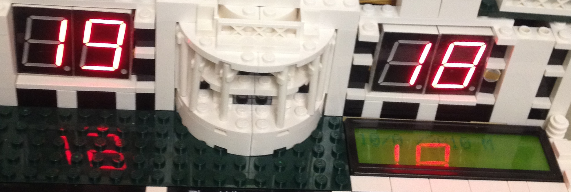
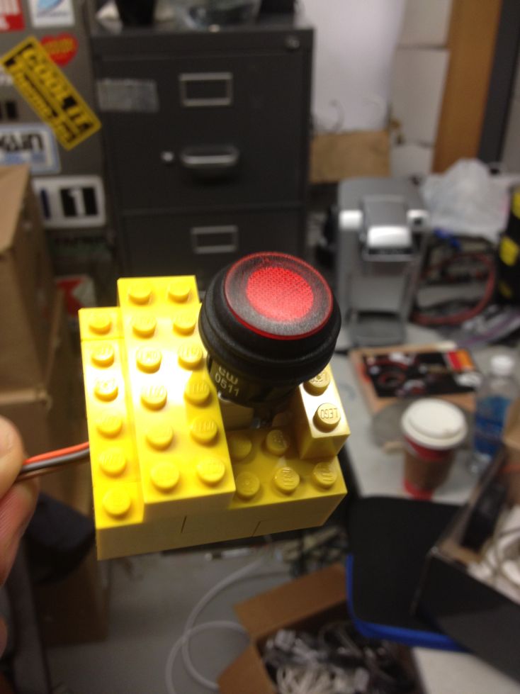
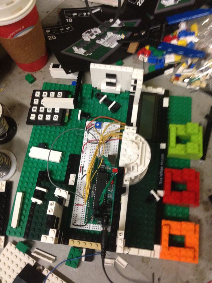
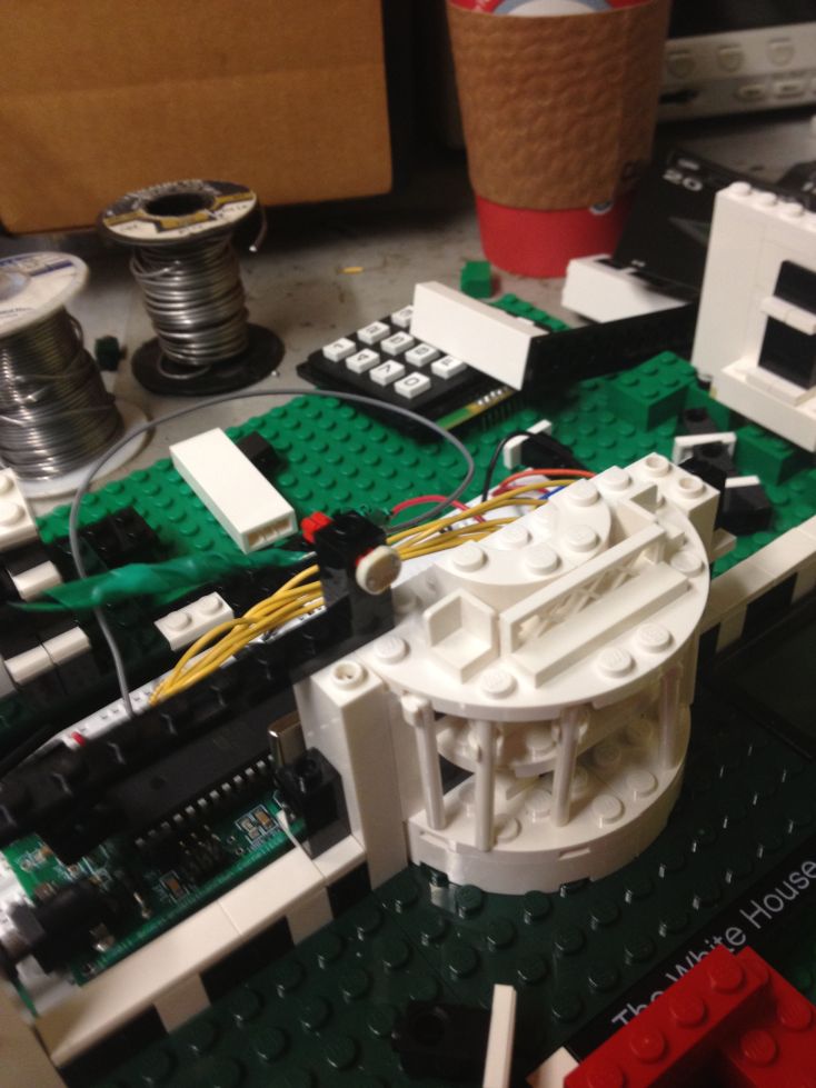
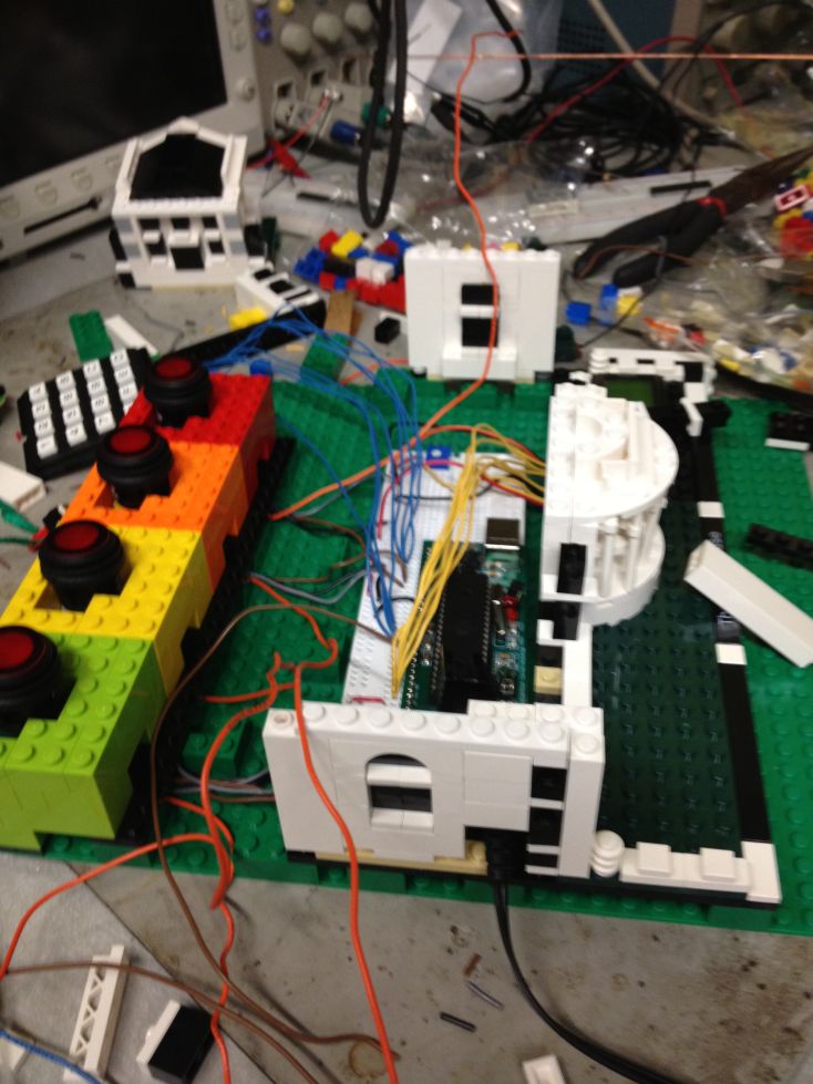
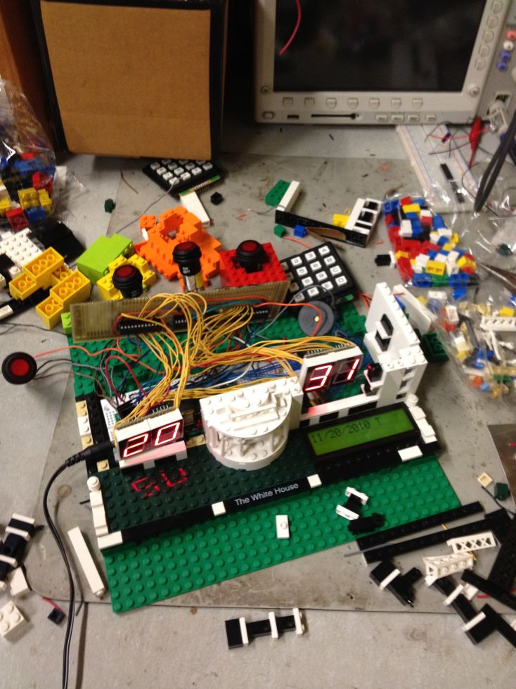
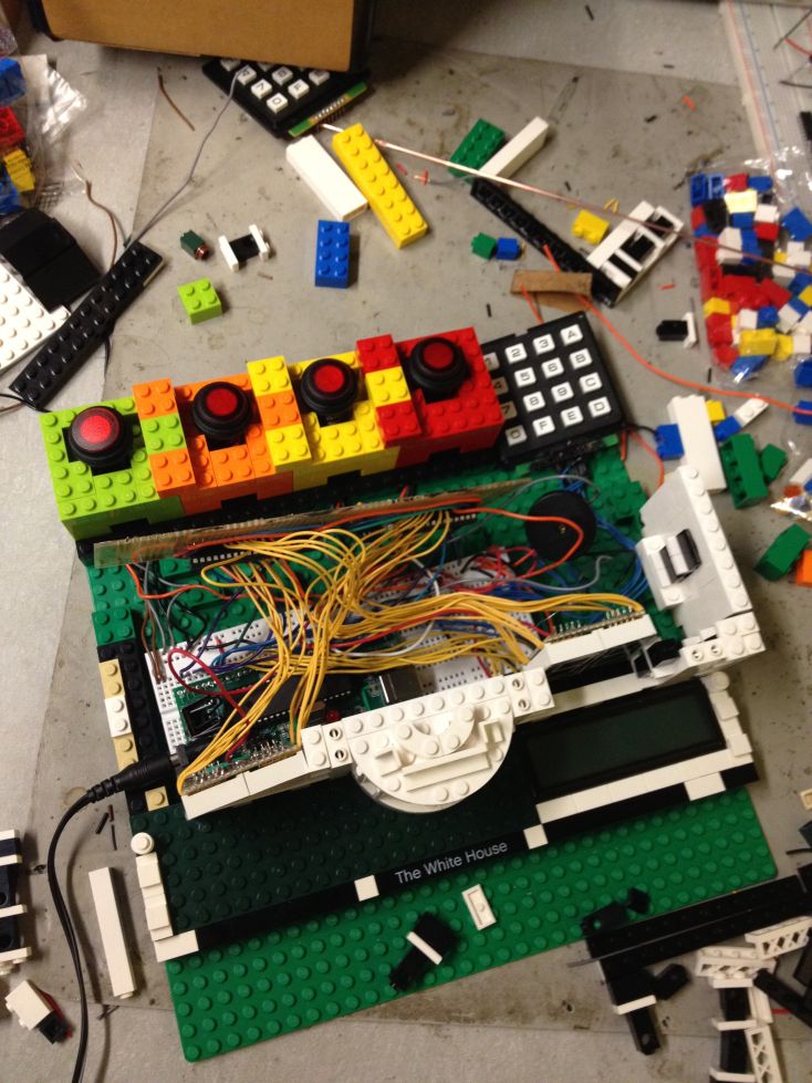
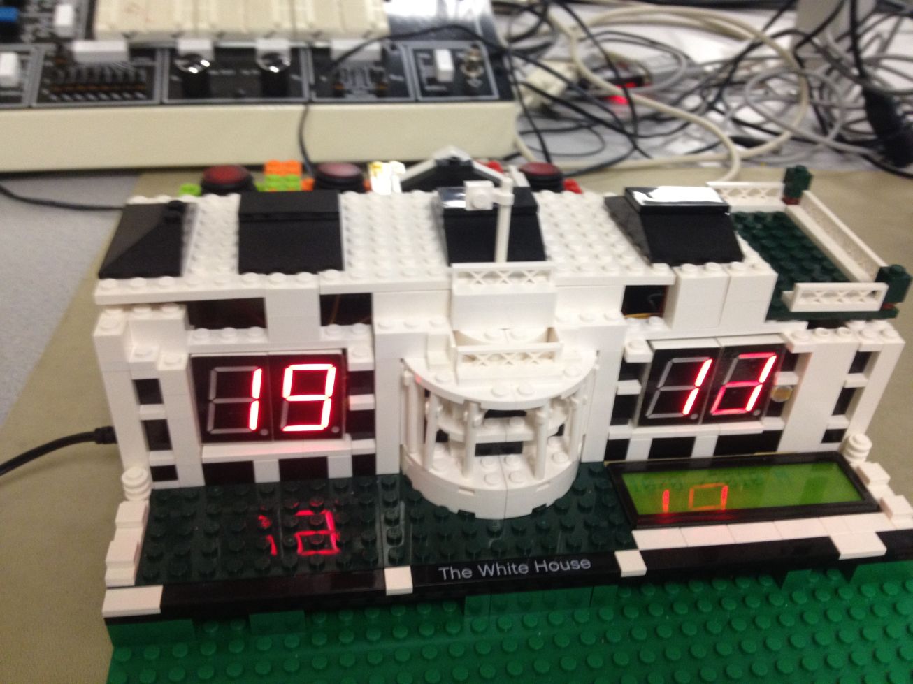
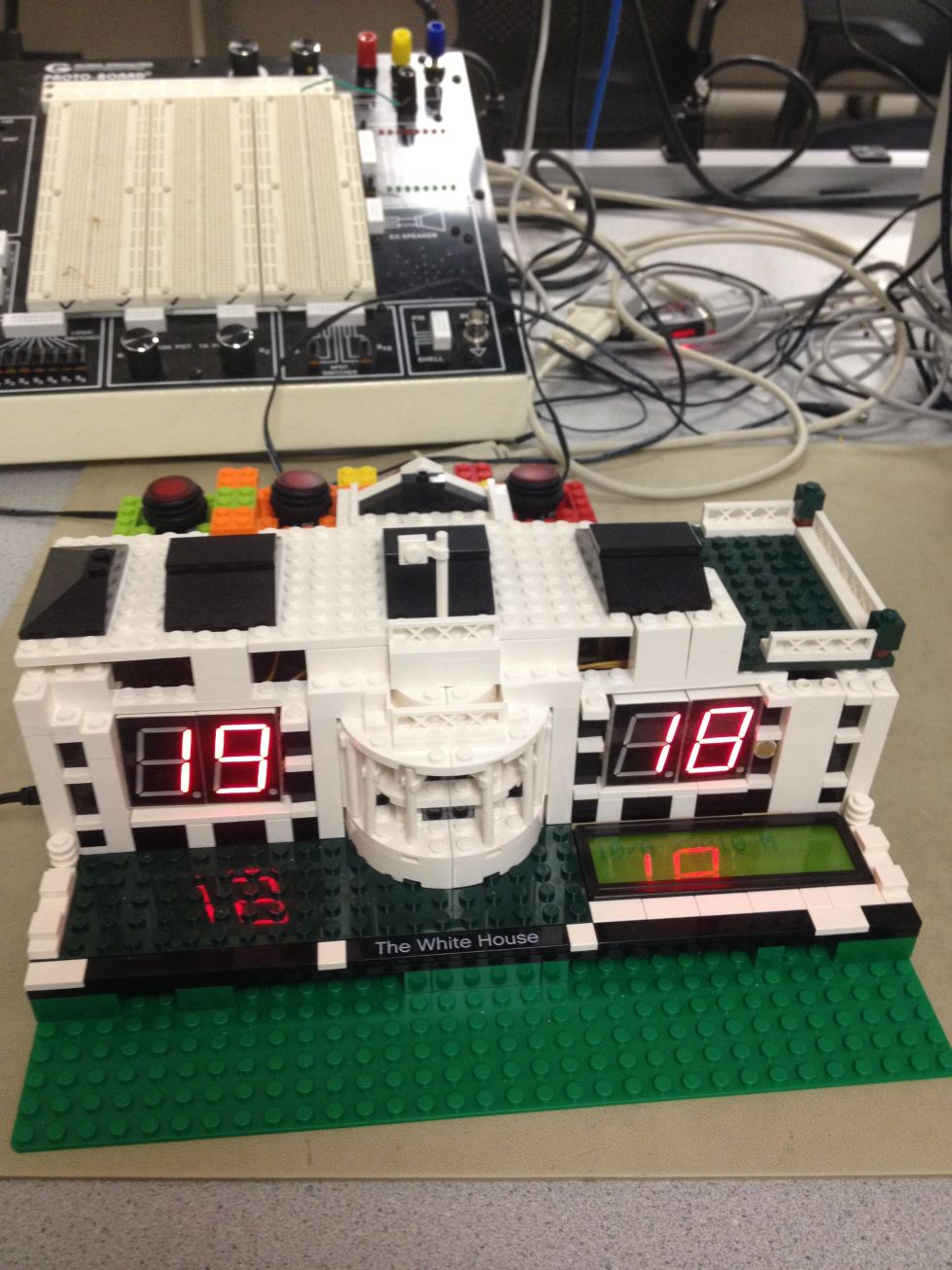
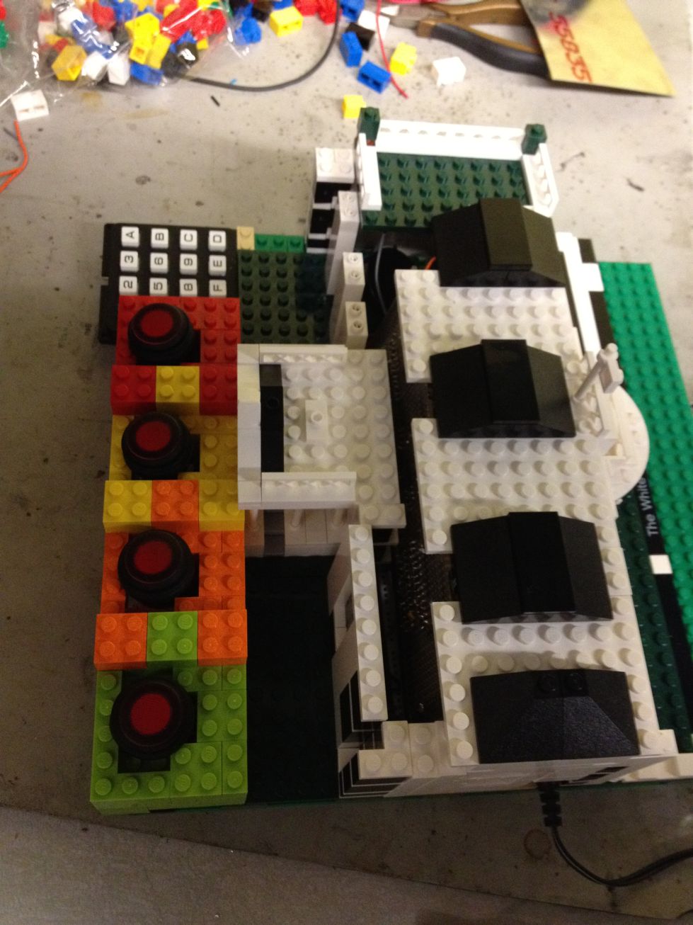
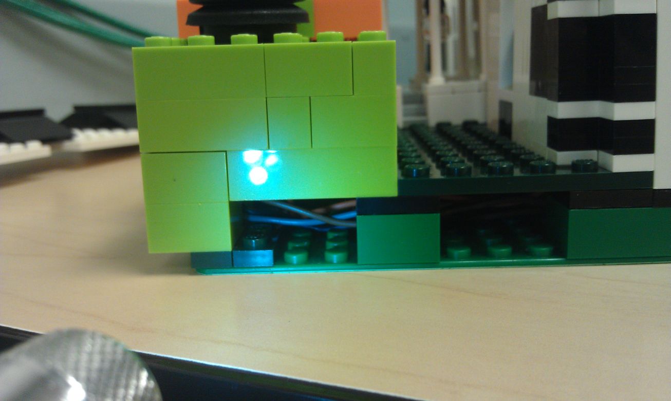
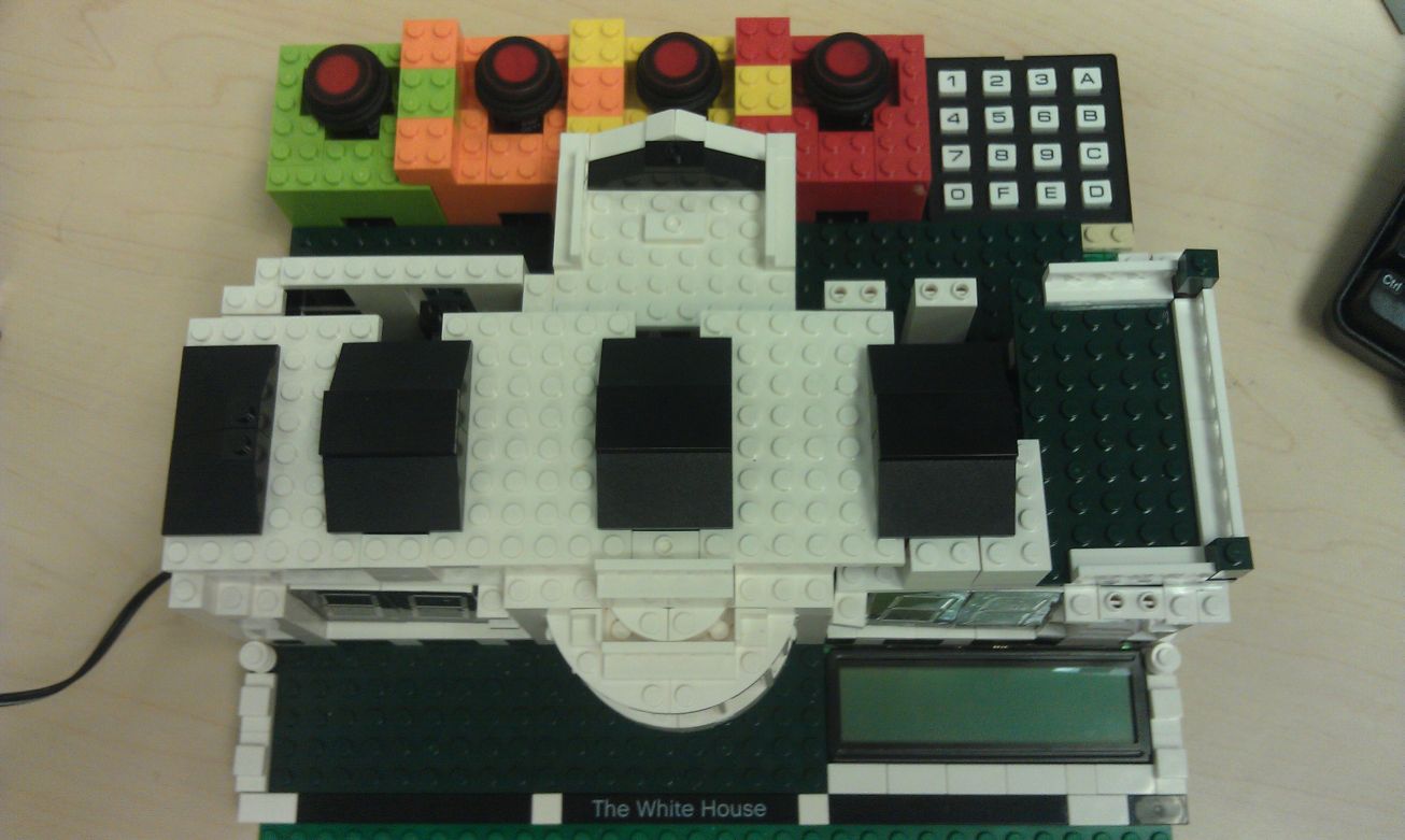
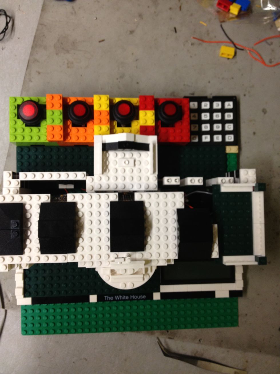
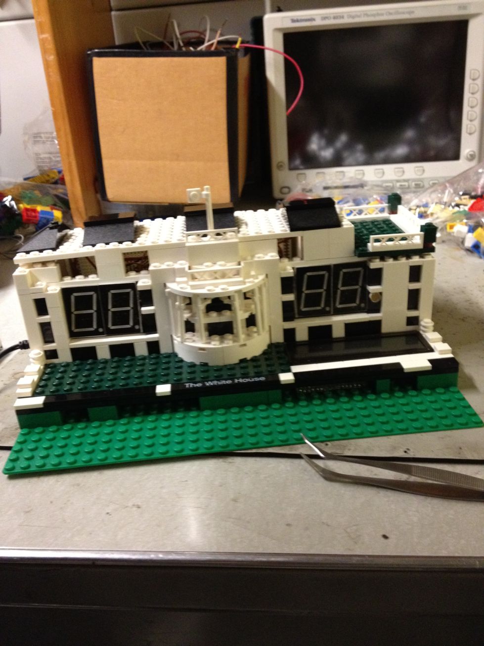
The shell of our alarm is built of LEGO bricks. We took apart a LEGO White House module and integrate our circuits into the White House. All the electronic parts fit perfectly with the LEGO parts. The overall appearance of the alarm clock looks compact and elegant. All the wires and chips are covered very well, including the power connector. Our project looks more like a final product rather than just a proof of concept.
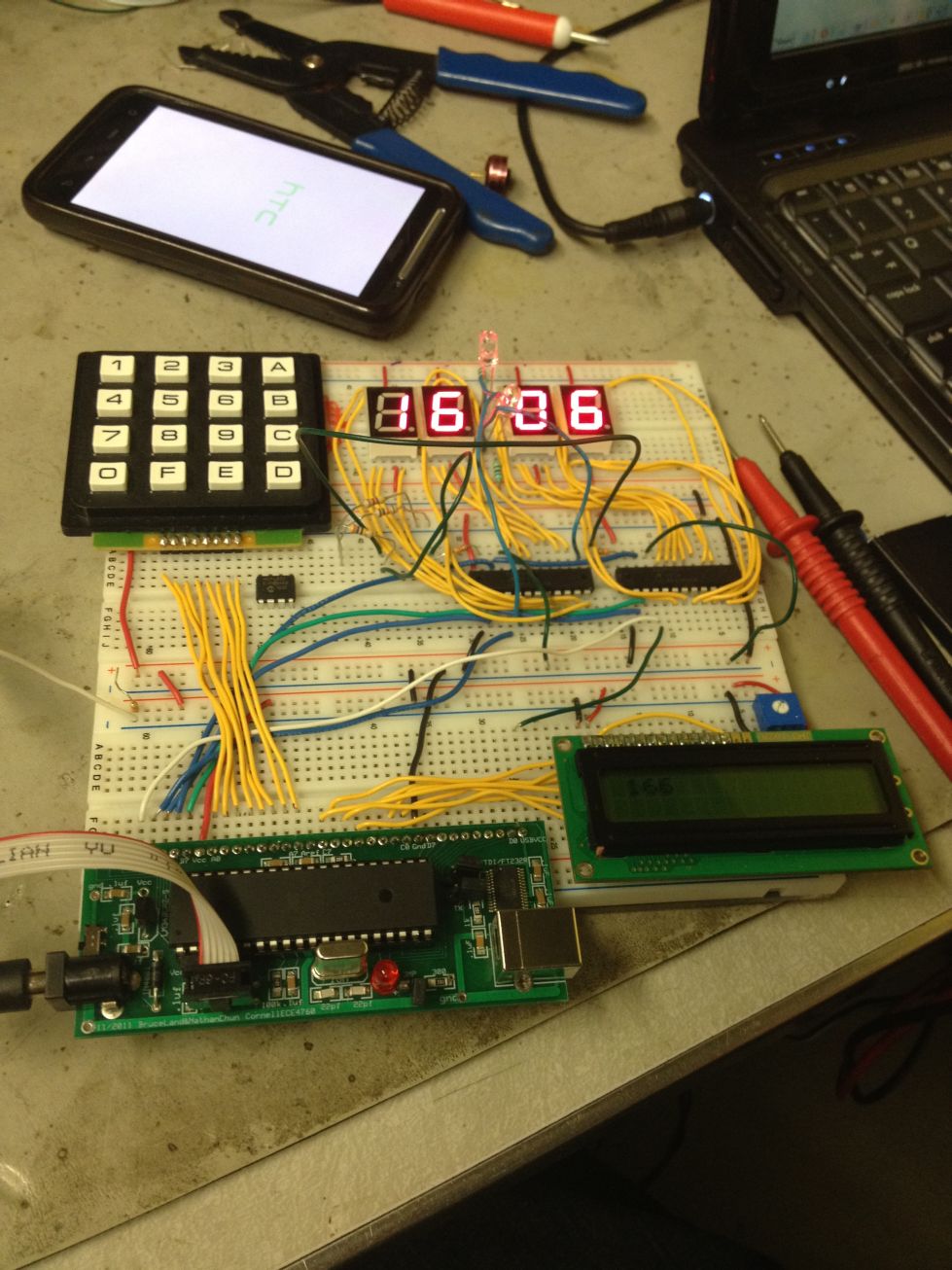
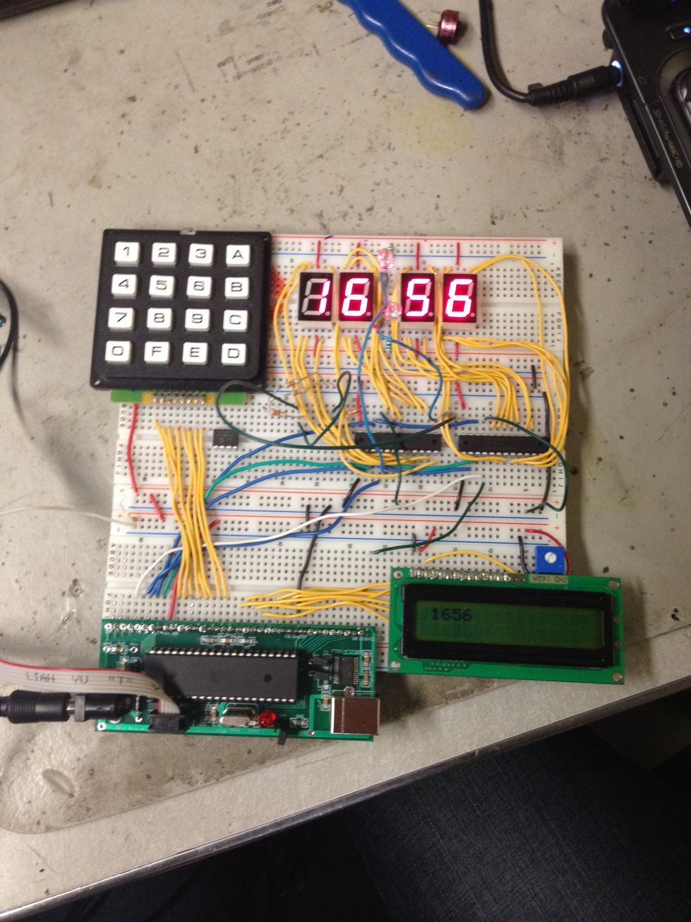
General Functionality
Most the features of the project are realized as proposed, and we added several enhancements to our initial proposal. The program will always react properly with any user input in any state. Date will be displayed on the LCD screen correctly and time will be displayed on the seven-segments accurately. The keypad and pushbuttons are sensitive to user inputs. The LCD screen and the seven-segment LEDs can display correct messages/numbers properly without any flicker. The brightness will be adjusted accurately and quickly according to the environment brightness. The buzzer will make moderate sounds when there is an alarm active. The alarms can be snoozed or disabled after correct operations. Multiple alarms in one day will all work correctly. All alarms will repeat weekly.
Accuracy
Since the time displayed on the LEDs is computed by the real time clock chip, it is very accurate and reliable. The error of the time is limited to less than 1 second per month. In the case of a sudden brightness change (room lights turned on/off) the LED brightness will be adjusted within 1 second.
Safety Considerations
Our project is safe to use in both short term and long term under proper operations. The user will never be exposed to high voltage. Even if the user takes apart the shell and touches the circuit, there is no hazard since the voltage is limited to 5 volts. The circuit won’t get very hot even after running continuously for several days, so there is no potential fire hazard. The only concern is that small kids might accidentally swallow the small LEGO parts or be hurt by the circuit if they try to break apart the shell. Parental supervision is recommended when kids are present.
Interference with Other Designs
Our project doesn’t have any interference with other people’s design. It runs individually without any strong output or side effect. The only outputs we have are the lights from the LEDs and the moderate sound from the buzzer.
Usability
Our alarm clock is designed to facilitate easy use. College students or adults will be able to easily use our design after reading the basic instructions. The user may forget some of the basic commands and the keypad layout when they first start using our design, but they will be able to use it proficiently after they get familiar with it. People with disabilities, bad eyesight or bad hearing may find our design difficult to use. A larger LCD and keypad, in addition to a louder buzzer will alleviate these issues.
The design overall was successful. It met our design expectations and we added some additional features. The Bluetooth module was not implemented but we were able to optimize the interface for data input with the keypad. The design is very stable and can be put to daily use. Future expansions could include interfacing the clock with a mobile phone and allow it to get data form your web enabled calendar. This way the device will be able to automatically program the dates itself. The device greatly improves on the shortcomings of current alarm clock designs.
Standards
Our design made use of two standard communication protocols. One of which I2C, the other SPI. SPI is used by both the DAC and the LED drivers. The I2C interface is used by the clock calendar chip.
Intellectual Property
As mentioned before, only one other standalone 7 day programmable alarm clock was found. We were only able to find patents protecting the device's user interface; not for their 7 alarm feature. Since the user interface of our clock is vastly different from theirs there are no patent conflicts.
We did however use some code that was available on the public domain. This includes the code used for the I2C interface, code for keyboard scanning, and code for the LCD interface. All the respective authors were cited where appropriate
One consideration for patents are to add to get LEGO to create a modular piece that they could use in their designs. This way consumers could design a housing for their own Lego clock.
Ethical Considerations
During the 4 weeks’ time of this project, we have been following the IEEE code of ethics in designing, implementing, testing, and reporting. Our design is a result of our original thought and our own efforts. We did receive help from the faculty, from our peers, and online, which are all noted in the reference section. We will be more than willing to help any other groups that may want our assistance in the future. We are providing our code as an example for others.
Although our design is not from a revolutionary thought, it is still very creative in a sense that we try to improve the existing technology and integrate different elements in one design. We intend to make a design that will benefit our peers with our knowledge and skills. Our design is a practical tool that has the potential to make the lives of many other students easier.
We made our project easy and safe to use. Also, we paid attention to safety issues in the lab when soldering and wiring. There has been no injury during the 4 weeks lab time. We also paid special attentions to the microcontroller heat so that there wouldn’t be any potential fire hazard because of overheating. Since our design has sound output, we turned down the volume of the buzzer in testing so that it wouldn’t affect other students in the lab.
We are reporting truthfully about our project. We are not purposefully misleading or masking known issues.


.jpg)
.jpg)
.jpg)
.jpg)