Cornell University ECE4760
I/O Ports
PIC32MX250F128B
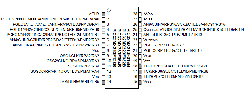
I/O Port Layout
- My slightly simplified version for 28 pin PDIP, organized so that humans can read it.
Click image for signal name definitions.
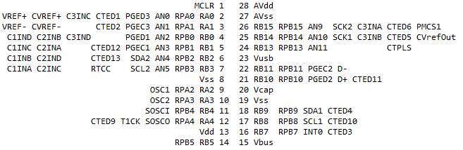
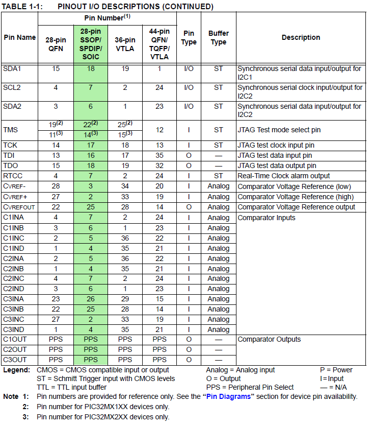
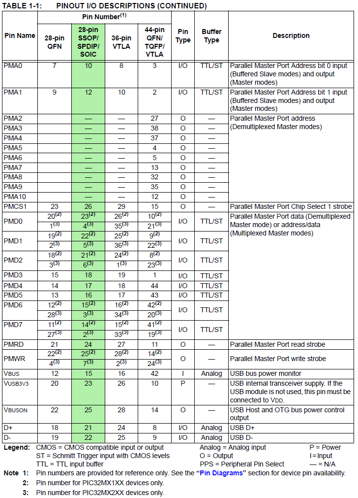
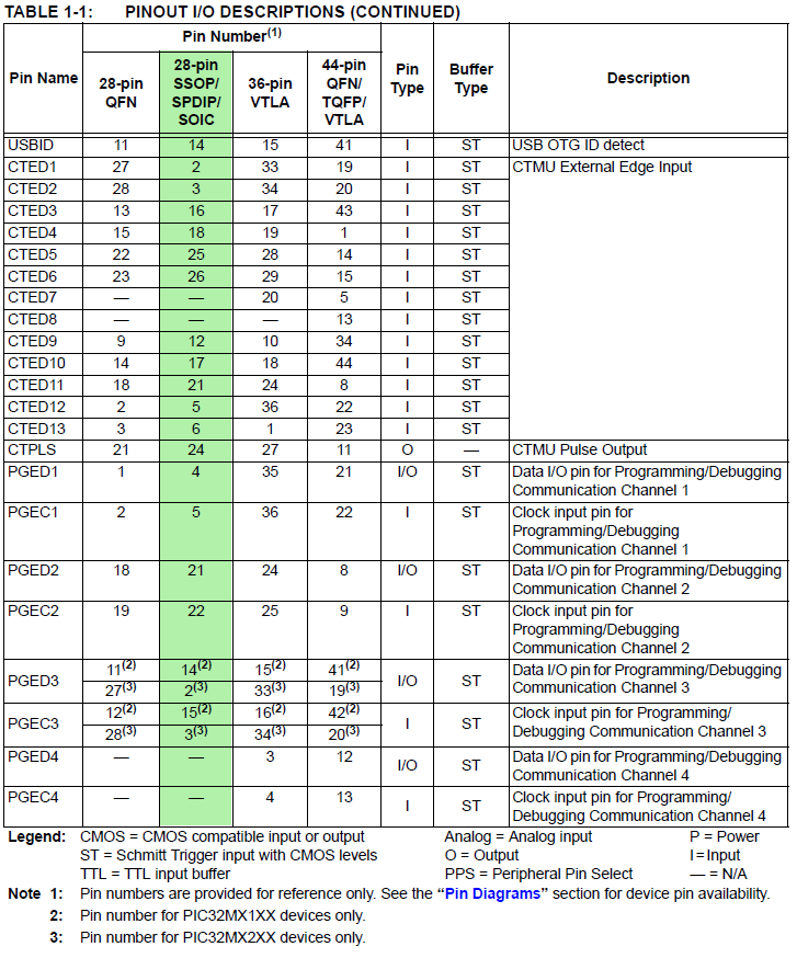
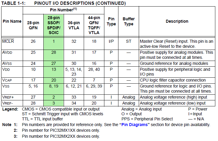
- Signal Names==>Pins: 1, 2, 3, 4, 5, 6, 7 PDIP highlighted in green
Some signals are locked to pins, others are on PPS
(for PPS see bottom off the page)
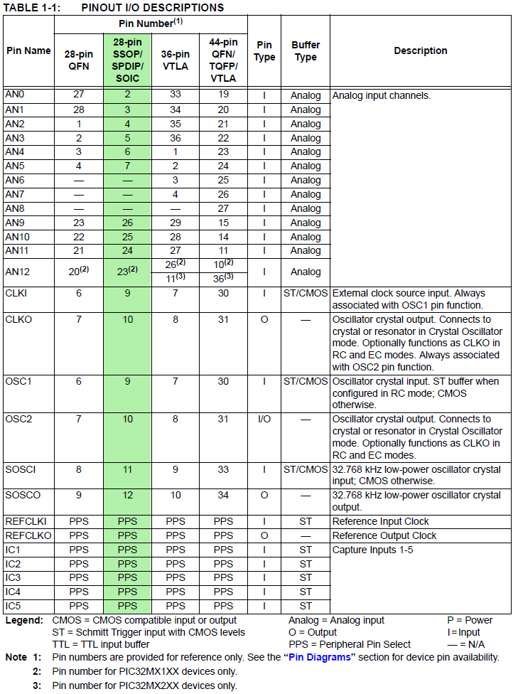
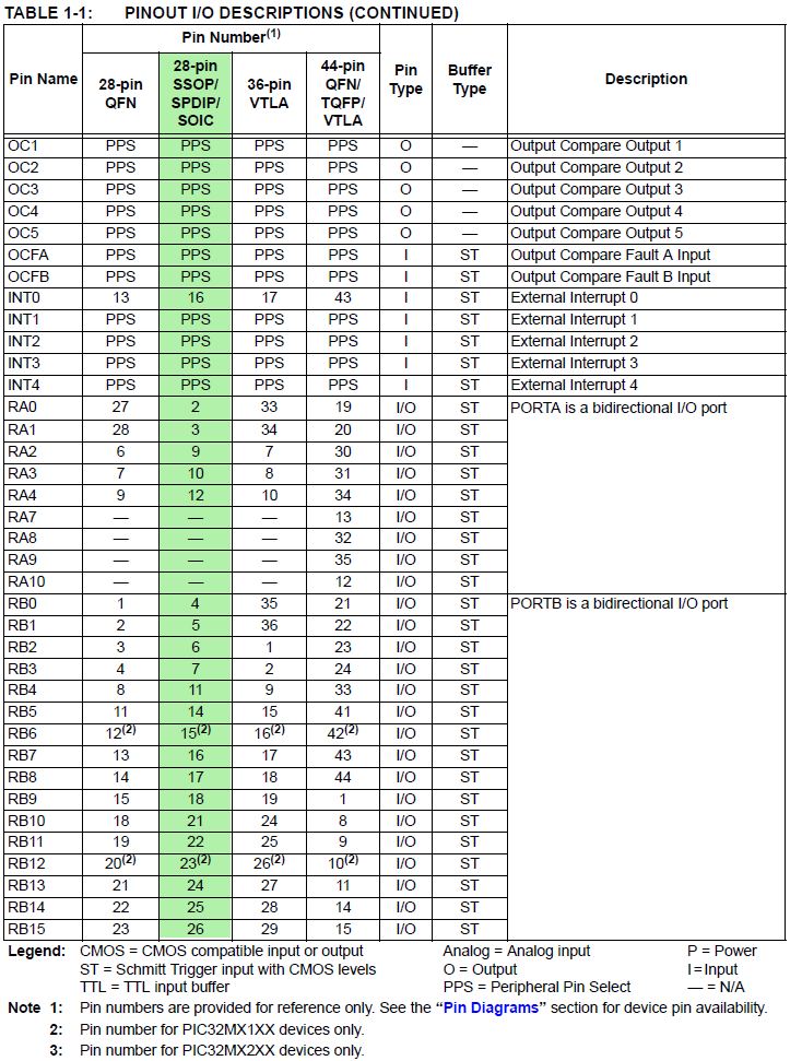
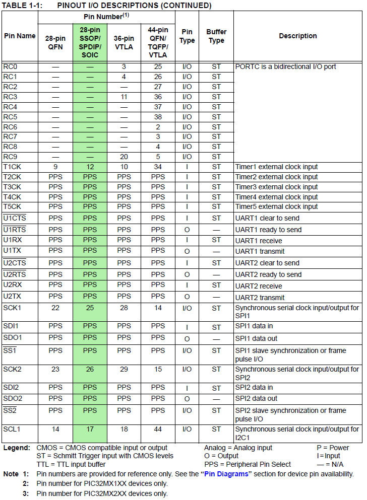
- PIC32MX250 full pinout
I/O Port structure
General purpose i/o pins have a variety of functions on the PIC32.
See also Chapter 12 of the Hardware Reference Manual and Chapter 10 of PLIB
- Always protect an input pin by placing a 300 ohm resistor between the pin and any
other circuitry, including another PIC32 pin! The reason for this is that it is quite easy to accidentally
connect two outputs together. If one directly connected output is logic-high and the other low, then they will be destroyed.
- Any portA or portB pin can be set to be an input or an output.
e.g. mPORTBSetPinsDigitalIn(BIT_7 | BIT_8 | BIT_9);
mPORTASetPinsDigitalOut(BIT_0 | BIT_1 | BIT_2 | BIT_3);
- Some pins may be configured for either analog or digital input.
The default is analog!
It is good practice to force all the pins to digital using:
ANSELA = 0; ANSELB = 0; (Protothreads does this for you)
Refer to the ADC page for information on setting up analog inputs.
- If the pin is an input it can be:
- High impedance -- data sheet says 1 microamp typical input leakage current
Always use this setting for reading analog voltages.
- Pulled down weakly -- typically 100 Kohms to Vss -- if you want a default input of logic 0
see below for macros
to control pulldowns.
Useful for reading the keypad.
- Pulled up weakly -- typically 20 Kohms to Vdd -- if you want a default input of logic 1
see below for macros to control pullups.
- If the pin is an output:
- Software or peripheral hardware can directly read i/o pins
e.g. mPORTBReadBits(BIT_7 | BIT_8 | BIT_9);
see PLIB manual 10.7 READ OPERATIONS
e.g. Correctly configured, the T1CK input signal can directly increment timer 1.
see Section 14 Timers, Figure 14.2
- Software or hardware events can directly set/clear individual pins and groups of pins (portA and portB)
e.g. mPORTAClearBits(BIT_0 | BIT_1 | BIT_2 | BIT_3);
mPORTBSetBits( BIT_6 | BIT_9);
mPORTAToggleBits(BIT_0);
see PLIB manual 10.8 WRITE OPERATIONS
e.g. an output compare unit can directly set/clear/toggle a pin without software intervention (once enabled).
- Special functions take over a pin when a specific peripherial is turned on.
When the special function is activated, the pin may not be used for general i/o.
e.g. When SPI1 is opened then the SCK1 clock is pin 25 (see full pinput) and portB, bit 14 is unavailable.
- Special functions may muxed onto one of several pins when a specific peripherial is connected using PPS.
See below for more details.
e.g. If SPI1 is opened, data out signal SDO1 may be on
any of 13 pins (See group 2 and 3 in table)
When the special function is connected to a pin, the pin may not be used for general i/o.
- Any i/o pin may be used as an interrupt source, using input change notification.
See details in Reference Manual 12.2.6 Registers for Input Change Notification
and
PLIB manual 10.5 CHANGE NOTICE AND WEAK PULLUP CONFIGURATION
Pullup/pulldown macros
The poorly documented CNPDB register (Change Notice Pull-down Enable B) selects input bits to pull down.
See section 12.2.6 of the i/o reference manual.
For instance, setting:
CNPDB = BIT_7 | BIT_8 | BIT_9
pulls down B7, B8, and B9. To be safe, you should probably clear the CNPUB register to turn off pull up resistors.
If you include the following macros:
// PORT B

#define EnablePullDownB(bits) CNPUBCLR=bits; CNPDBSET=bits;

#define DisablePullDownB(bits) CNPDBCLR=bits;

#define EnablePullUpB(bits) CNPDBCLR=bits; CNPUBSET=bits;

#define DisablePullUpB(bits) CNPUBCLR=bits;

//PORT A

#define EnablePullDownA(bits) CNPUACLR=bits; CNPDASET=bits;

#define DisablePullDownA(bits) CNPDACLR=bits;

#define EnablePullUpA(bits) CNPDACLR=bits; CNPUASET=bits;

#define DisablePullUpA(bits) CNPUACLR=bits;
Then you can just write
EnablePullDownB( BIT_7 | BIT_8 | BIT_9);
There is support for pullup in PLIB
(ConfigCNPullups) but it is not organized by port bit number and there is
no support for pulldowns that I could find.
PPS
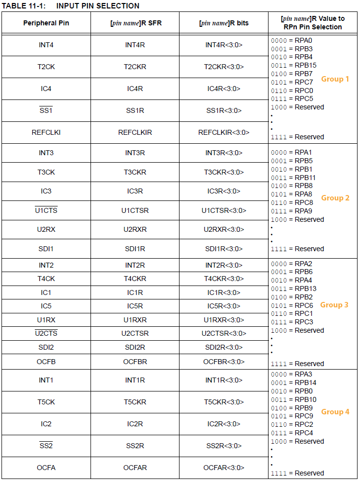
PPS redirects specific logical input/output signals to groups of i/o pins. For instance, one of the input capture inputs, IC1, can be routed to one of 8 different physical pins (see input table below). This feature helps with fitting designs onto the relatively few pins on the PDIP PIC32. Note that not all logical device signals can be PPS routed. For example, when an SPI channel is turned on, SCL1 and SCL2, the SPI clock lines are at fixed i/o pins 25 and 26 (RB14 and RB15). When a SPI channel is disabled, the respective clock pin can be used for general i/o.
Using PPS input-- PIC32MX250F128B Peripheral Pin Select (PPS) input table
-- example -- UART receive pin
specify PPS group, signal, logical pin name
PPSInput(2, U2RX, RPB11); //Assign U2RX to pin RPB11 -- Physical pin 22 on 28 PDIP
Note that the groups (1 to 4) are delimited by horzontal lines in the righthand column.
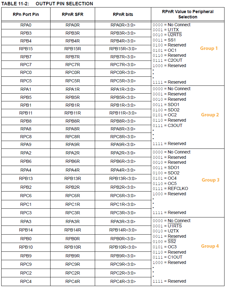
Using PPS output -- PIC32MX250F128B Peripheral Pin Select (PPS) output table
-- example -- UART transmit pin
specify PPS group, logical pin name, signal
PPSOutput(4, RPB10, U2TX); //Assign U2TX to pin RPB10 -- Physical pin 21 on 28 PDIP
Note that the groups (1 to 4) are delimited by horzontal lines in the righthand column.
Copyright Cornell University
September 30, 2019