ECE 4760: Laboratory 2
Cricket Call Generator.
Introduction.
You will construct a cricket-call generator which will produce audio output
of a simplified cricket call.
A cricket call may be very complex, but we will
limit ourselves to the following form.
- A call is made up by indefinitely repeating a chirp and a silent period.
The chirp starts again after the chirp repeat interval.
- A chirp is made up of a certain number of syllables,
each with specific duration and syllable repeat interval.
- A syllable is made up of a sine wave burst at a certain burst frequency.
The burst
starts at low amplitude, which increases quickly to a maximum,
sustains the
maximum amplitude until just before the end, then decreases amplitude to zero.
The image below summerizes the definition ( from Manfred
Hartbauer).
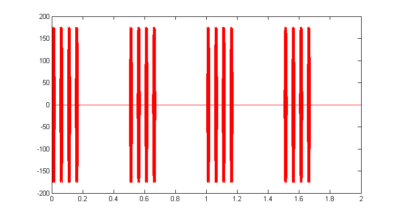
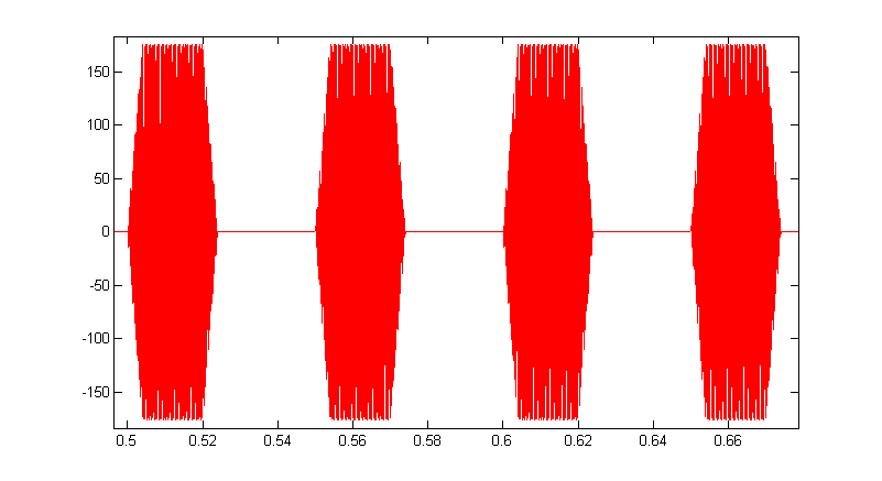
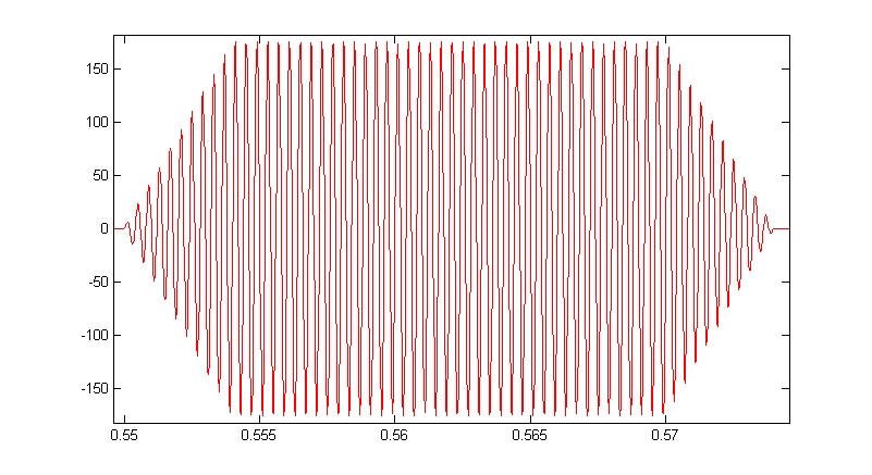
A matlab program generates such songs, but is not real time. The following images are three zoom levels of a song generated with chirp_repeat_interval=0.5 sec, syllable_duration=0.02, syllable_repeat_interval=0.05, syllable_count=4 and burst_freq = 2500 Hz. The syllable rise time was set to 4 mSec. The second image shows one chirp of the first image and the thrid image show one syllable of the second image.
Procedure:
You will use a keypad to control cricket synthesis with audio output to a speaker. Analog output will be through a SPI controlled DAC.
The analog signal will
be sine wave bursts generated using Direct Digital Synthesis
(DDS) technique to one one channel of the DAC. An example shows how you might implement
a DDS, with the SPI DAC. Your DDS unit must resolve 256 table entries. For this lab, you will need to modulate the amplitude on a per-sample basis. The sine wave table may need to be scaled to prevent overflow. Use the DAC and keypad examples shown on the Dev board page.
SPI DAC
- The SPI DAC you will use is the MCP4822. The connection and setup is described on the SPI page
- You will need to get user input from a keypad as explained on the TFT/keypad page.
BUT Use the DAC and keypad examples shown on the Dev board page.
The connector pins marked DACA and DACB will go (optionally through a low pass filter) to an audio socket, to be connected
to the green audio plug of the speakers.
Audio socket  . The pin nearest the socket is ground. Wire the left/right channels together. Speaker Plug
- Possible pin assignments for keypad, DAC and keypad
All TFT and DAC connections are constructed on the big board for you.
- TFT uses
pins 4,5,6, 22 and 25 (RB0, RB1, RB2, MOSI1, SCLK1)
SCK1: connected to RB14 on the PIC
MOSI (SDO1): PPS output group 2 connected to RB11 on the PIC
CS: connected to RB1 on the PIC
SDCS: left unconnected as I'm not using the microSD card for this
RST: connected to RB2 on the PIC
D/C: connected to RB0 on the PIC
VIN: connected to 3.3V supply
GND: connected to gnd
- DAC input SPI channel 2 uses
SCK2 pin 26
SDO2 (MOSI) is in PPS output group 2, could be connected to RB5 which is pin 14, but remember to set #pragma config JTAGEN = OFF, DEBUG = OFF
pin 11, but remember to set #pragma config JTAGEN = OFF, DEBUG = OFF
The OUTPUT of the DAC are the pins DACA and DACB on the big board
- Keypad -- need 7 i/o lines (see schematic on the TFT/keypad page)
A0 to A3 and B7 to B9
In this lab and every lab, make sure you are running Protothreads 1_2_1.
I suggest organizing the code as:
- Protothreads maintains the ISR-driven millisceond-scale timing.
- Timer ISR running at the DDS sample rate to update the DDS, do the modulation, and signal the DAC.
- Main sets up peripherials and protothreads then just schedules tasks, round-robin.
- Keypad Thread
- scans the keypad
- runs the debounce state machine (state machine pseudocode for ONE buttton)
- places valid keypresses into a digit buffer and sets up the systhesis parameters
- waits for 30 mSec.
- sets the DDS parameters for the sine wave (if any) which is playing.
- Starts/stops the play back
Assignment
- Write a C program which implements a cricket-call generator with the following
specifcations:
- Generate sinewaves using DDS. The sinewaves should be built from
8-bit samples (taken from a 256 entry table).
- The LCD and keypad will be used to enter arbitrary combinations of the
5 parameters shown below.
The keypad must be debounced. The LCD display must have enough information so that the user can determine
which parameter is being set and the value of the parameter.
The four calls shown are typical of real cricket
species, but you must not limit the program to these four calls.
The range which can be set is shown in the 5th row.
All times
are in milliSeconds. Frequencies are in Hz.
| parameter |
chirp
repeat
interval
|
number of syllables |
syllable
duration |
syllable
repeat
interval |
burst
frequency |
| call 0 |
20 |
1 |
10 |
--- |
4500 |
| call 1 |
250 |
4 |
18 |
30 |
5000 |
| call 2 |
1500 |
50 |
8 |
20 |
6000 |
| call 3 |
1000 |
5 |
30 |
50 |
3000 |
| Range |
10 to 1000 |
1 to 100 |
5 to 100 |
10 to 100 |
1000 to 6000 |
- All time intervals and burst duration accuracy should be +/-1
mSec.
- Each sine wave burst must be amplitude modulated from zero to full amplitude
in 4 mSec at the beginning of a burst and full to zero in 4 mSec at the
end.
Syllable duration is taken to be the width of the burst at half-amplitude.
- There will be control buttons to play, stop, and test frequency.
These buttons do not need to be on the keypad:
- There will
be a play and a stop button to start and stop song production. The song will start immediately when the start button is pushed and play until the stop button is pushed.
- There must be a separate frequency test mode which contiinuously produces the burst frequency in order to use the scope FFT to determine the following:
- Frequency accuracy should be +/-1%.
- Harmonic distortion should be -20db from fundamental amplitude.
- Connect the circuit to a speaker audio input (green phone plug) and listen
the output.
The audio should be free of clicks/pops caused by steps in the output waveform.
This will aid in debugging and is required for the demo.
- Demo this program to a staff member. Show that all specifications are met
by verifying frequencies with an oscilloscope.
- At no time during the demo should you need to press RESET.
- Your written lab report should include the sections mentioned in the policy page, and :
- How you generated the freqencies (DDS resolution, etc) and an measurement
of how accurate they are.
- Oscilloscope capture of typical waveforms.
- Oscilloscope capture of FFT to show that harmonic distortion meets the spec
- How you generated the various time intervals required by this project.
- A diagram of the state machine you used to debounce. One of the TAs (Shiva) recommends drawing FSM with fizzim.
- Other design aspects of the assignment, such as the conversion from
user input frequency in Hz to DDS increment.
- A heavily commented listing of your code.
Copyright Cornell University
September 26, 2017