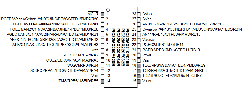
When you click on the images below, you will get enlargments with the pin numbers indicated.
You will produce a digital capacitance meter (DCM) which displays the capacitance on the graphic LCD. The DCM will
measure capacitances from 1 to 100 nF.
But first you need to set up a board, arrange jumpers, learn how to connect peripheral devices and use the compiler. I strongly suggest that you use some of the time during the first lab exercise to build your own PIC32 board, which you can then keep, but if you wish you can borrow one. Once you do that, the MicrostickII will be the programmer for the new board.
Hardware
The Big Board which you will build features a port expander, DAC, TFT header-socket, programming header-plug, and power supply.
See the construction/testing page for specific code examples of each device on the big board.
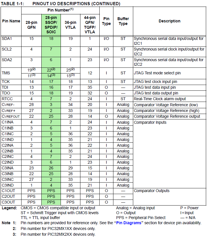
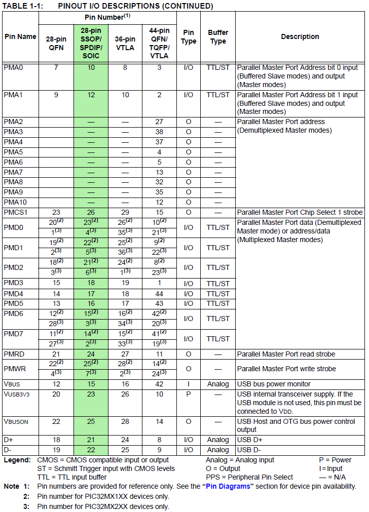
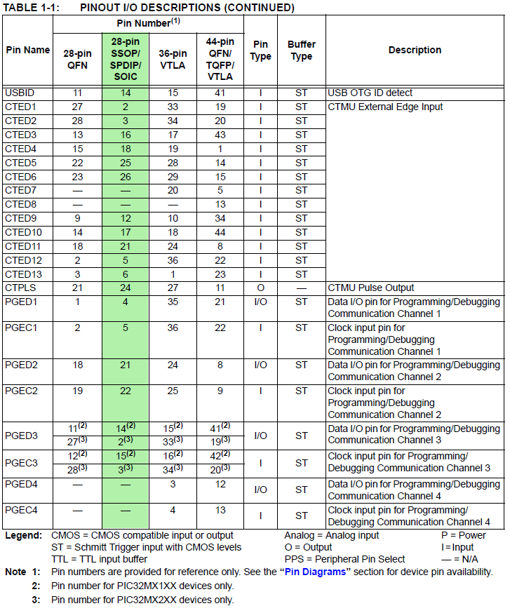
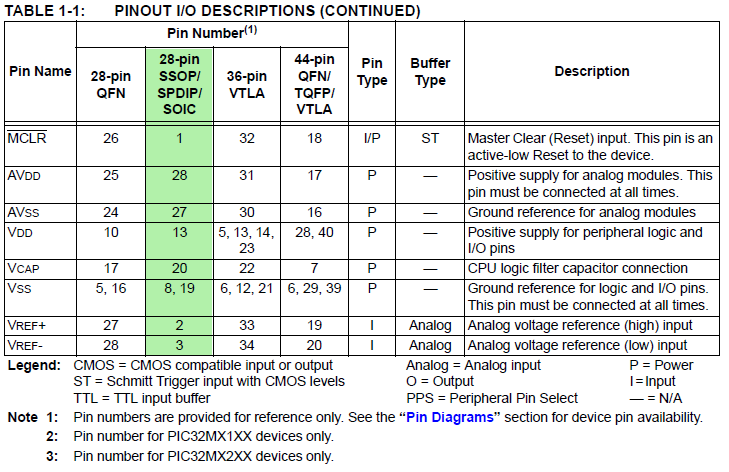
The connections from the PIC32 to the various peripherials is determined by the construction of the board. The list is repeated here.
PIC32 i/o pins used on big board, sorted by port number. Any pin can be
recovered for general use by unplugging the device that uses the pin.
SPI chip select ports have jumpers to unplug.
----------------------------
RA0 on-board LED. Active high.
RA1 Uart2 RX signal, if serial is turned on in protothreads 1_2_2
RA2 port expander intZ
RA3 port expander intY
RA4
PortExpander SPI MISO
-----
RB0 TFT D/C
RB1 TFT-LCD SPI chip select (can be disconnected/changed)
RB2 TFT reset
RB4 DAC SPI chip select (can be disconnected/changed)
RB5 DAC/PortExpander SPI MOSI
RB6 !!! Does not exist on this package!!! (silk screen should read Vbus)
RB9 Port Expander SPI chip select (can be disconnected/changed)
RB10 Uart2 TX signal, if serial is turned on in protothreads 1_2_2
RB11 TFT SPI MOSI
RB12 !!! Does not exist on this package!!! (silk screen should read Vusb3.3)
RB14 TFT SPI Sclock
RB15 DAC/PortExpander SPI Sclock
----------------------------
But note the few silk-screen errors on the board.
Big Board silk screen errors.
--Edge connector pin marked RB6 -- RB6 Does not exist on this package! Silk screen should read Vbus.
--Edge connector pin marked RB12 -- RB12 Does not exist on this package! Silk screen should read Vusb3.3.
--LED D1 outline -- Silk screen should have flat side should be oriented toward PIC32.
Software
Software you will use is freely downloadable and consists of:
More information
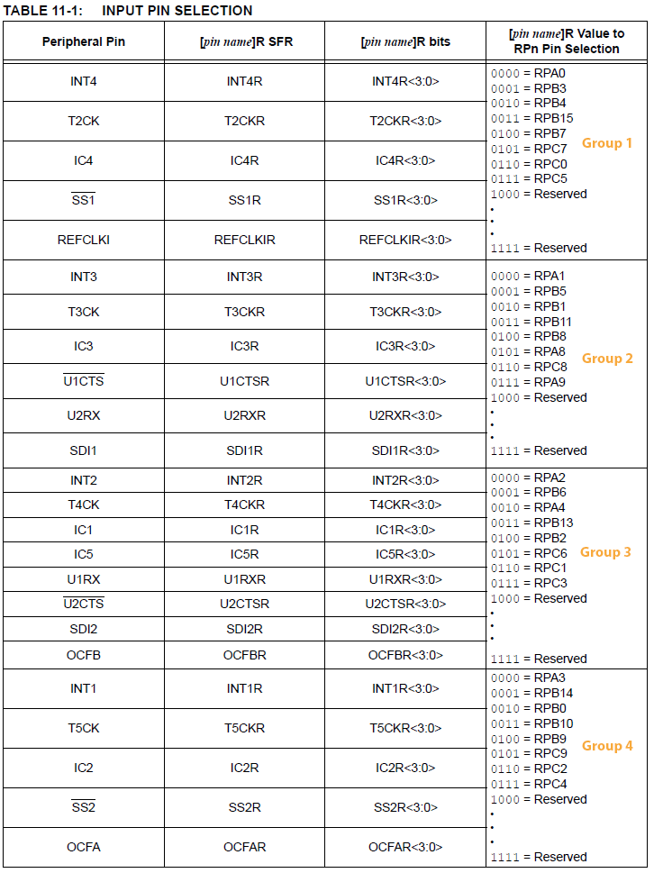
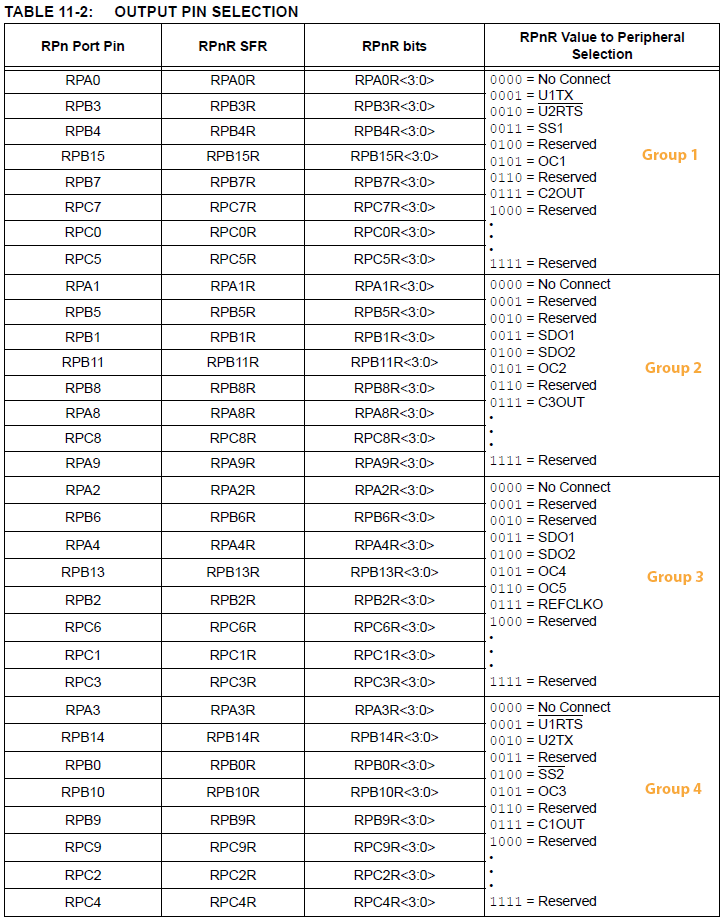
PPSInput(2, U2RX, RPB11); //Assign U2RX to pin RPB11 -- Physical pin 22 on 28 PDIP PPSOutput(4, RPB10, U2TX); //Assign U2TX to pin RPB10 -- Physical pin 21 on 28 PDIP Microstick2 as a programmer
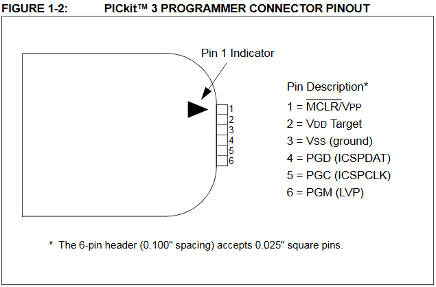
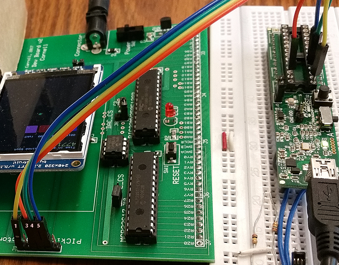
The connections to the microcontroller socket on the Microstick2 act like the standard programming signals from the PICKIT3, the programmer which was used to develop the boards you will build. On both the big and small board, J1 marks pin1 of the 6-pin ICSP header.
| Signal | PICkit3 (ICSP) connector on board |
Microstick2 DIP Pins |
|---|---|---|
| MCLR | 1 | 1 |
| ground | 3 | 27 |
| prog data (PGD) | 4 | 4 |
| prog clock (PGC) | 5 | 5 |
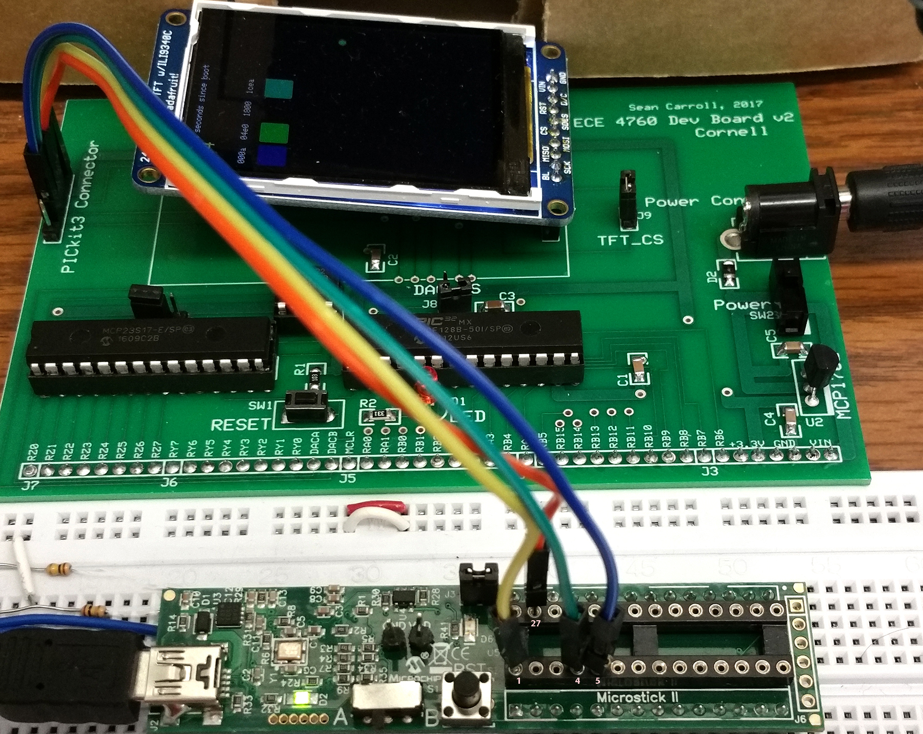
A wiring example is shown below. Note that pin 1, MCLR, is only available on the Microstick2 DIP socket as shown.
When you click on the images below, you will get enlargments with the pin numbers indicated.
Testing the board after you build it.
Using the programmer you just connected, compile, load and run the Board test example on the board construction page.
Make sure that the TFT, the DAC, and LED work. As described on the page.
Be sure to attach the chip-select jumpers for the TFT and DAC!
Procedure
OpenChoice Desktop in the start menu, and start the program. Select Instrument.USB device, and click OK.Get Screen.Capacitance measurement
The approach we will use is to measure the time it takes for a RC circuit to
charge a capacitor to a given level. Using the IVref internal voltage reference, then the level will be v(t1.2)=1.2±0.06 . Since the internal reference has 5% possible error, you will need to calibrate for the voltage for your chip. One way to do this is to perform a linear regression of capacitance and rise time. Specifically,
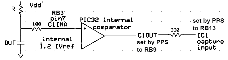
we will use the internal analog comparator as shown in the following
diagram to trigger a timer capture event. The C1OUT pin needs to be connected to one of the event capture channels, with IC1 shown. Since R will be known, we can get C because the voltage on the capacitor v(t)=Vdd(1-exp(-t/τ)) with τ=R*C.
The capacitor shown is the device you are trying to measure.You must choose one value of R
so that the capacitor charging time is not too short or too long over the whole range of C. If it is too short (say, less than 100 counts) you will lose measurement accuracy. If it is too long, the timer will overflow (16-bits). The value of R you choose will be partly constrained by the timer prescalar, but should not be bigger than 1Megohm, or smaller than about 10K, as explained below.
The 100 ohm resistor limits discharging current when using pin 7 (B3) as an output.
The following code snippet is sufficient to set up internal compare1 and read C1OUT with the oscilloscope. Note that C1INA is fixed to RB3, but that C1OUT is on PPS output (group 4).
//set up compare 1)
CMP1Open(CMP_ENABLE | CMP_OUTPUT_ENABLE | CMP1_NEG_INPUT_IVREF);
PPSOutput(4, RPB9, C1OUT); //pin18
mPORTBSetPinsDigitalIn(BIT_3); //Set port as input (pin 7 is RB3
One thread of your program will have to (in time order):
R>100*(100ohms).
I suggest that you organize the program as follows:
capture1 = mIC1ReadCapture(); PT_YIELD_TIME_msec(wait_time) PT_YIELD_TIME_msec(200), then repeats.You may find some of previous year's lectures useful. Particularly lectures 2, 3, 4.
Week one required checkpoint
By the end of lab session in week one of the lab you must either have:
Assignment
Timing of all functions in this lab, and every exercise in this course will be handled by interrupt-driven counters, not by software wait-loops.
ProtoThreads maintains a ISR driven timer for you! This will be enforced because wait-loops are hard to debug and tend to limit multitasking.
Write a Protohreads C program which will:
C = xx.x nf to the LCD. When you demonstrate the program to a staff member, you should demonstrate that the capacitance is correct within the tolerance of the resistors you use. Your program should not need to be reset during the demo.
Your written lab report should include the sections mentioned in the policy page, and :