DES
DES was the first module to be completed. It consists of control lines that include a clock, sys_reset, signal_done, signal_next and signal_match. signal_done is an output, it is set high when DES has finished computing a hash. signal_next is an input to the module. This signal recycles the DES state machine, telling it to start computation of the next hash. The hash and match signal are both used to check for matches. The hash signal comes from the controller and is set to the hash to look for. When DES is done computing a hash, it checks it against this value. If there is a match, the match signal is asserted, otherwise DES will wait for a new key and signal_next.
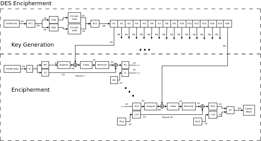
DES is implemented as a state machine in Verilog. The DES algorithm is depicted above. Subkeys are generated and applied to the 64 bit data in 16 rounds. This process takes 18 clock periods to complete because of the 18 state in the design. Therefore, the time DES takes to compute a hash is proportional to the internal clock driving the state machine and is given by 18 times the clock period. The maximum clock rate found to work in the timing simulator was 100 MHz or 10ns which corresponds to 200ns per hash or 5 million hashes per second for a single DES unit. This is the absolute maximum rate. An unoptimized version of [Red] running on a 27 MHz internal clock computed hashes at a rate of 1.5 million per second, about 700ns per hash.
Counter
Ten very special counters sit in the core of the key generator. This is the Verilog that describes how it is used.
count count0(b1[0],b2[0],b3[0],b4[0],b5[0],b6[0],b7[0],c_clk,rst,7'd0);
count count1(b1[1],b2[1],b3[1],b4[1],b5[1],b6[1],b7[1],c_clk,rst,7'd1);
count count2(b1[2],b2[2],b3[2],b4[2],b5[2],b6[2],b7[2],c_clk,rst,7'd2);
count count3(b1[3],b2[3],b3[3],b4[3],b5[3],b6[3],b7[3],c_clk,rst,7'd3);
count count4(b1[4],b2[4],b3[4],b4[4],b5[4],b6[4],b7[4],c_clk,rst,7'd4);
count count5(b1[5],b2[5],b3[5],b4[5],b5[5],b6[5],b7[5],c_clk,rst,7'd5);
count count6(b1[6],b2[6],b3[6],b4[6],b5[6],b6[6],b7[6],c_clk,rst,7'd6);
count count7(b1[7],b2[7],b3[7],b4[7],b5[7],b6[7],b7[7],c_clk,rst,7'd7);
count count8(b1[8],b2[8],b3[8],b4[8],b5[8],b6[8],b7[8],c_clk,rst,7'd8);
count count9(b1[9],b2[9],b3[9],b4[9],b5[9],b6[9],b7[9],c_clk,rst,7'd9);
The final design uses 10 counters in parallel, each responsible for generating a single key. Counters counts up by 10 at a time but started at different values. Counter count0 starts counting at 0, count1 at 1, count2 at 2, count9 at 9 etc... On a positive clock edge, all counter increase by 10. Resulting values for count0, count1, count2 and count9 then are 10, 11, 12 and 19 respectively. If the posedge of the clock is generated four times, 4 times 10, 40 keys can be produced every 400ns at a 27 MHz internal clock. The maximum internal clock rate was found by timing simulation to be 30ns or 33MHz, a rate of 120 million keys generated per second.
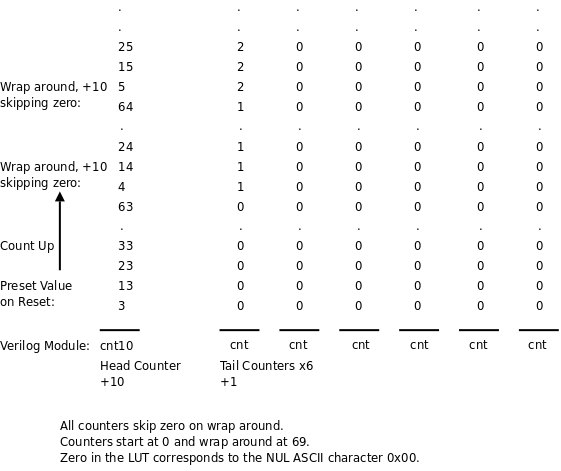
Each counter is made up of seven individual counters of two different types, cnt10 and cnt. Seven are needed because passwords are at most 14 characters long and divided into two halves. To facilitate counting by 10, the head counter, representing the least significant bit, needed to be different. The head counter counts by 10 and has the ability to load a preset value on reset so that it can count starting at an offset. Tail counters count up by 1. Both head and tail counter start counting from 0 or the preset value to 69, wrap around and skip zero. Skipping zero on all subsequent wrap around is very important. The output of each counter is connected to a lookup table to do the translation from count value to ASCII key. Zero in the LUT represents NUL. NUL is not a valid character in the LM keyspace but exists only to pad the string. NUL is necessary as a initial value in this design for positions not yet reach by the counter. The figure below illustrates the peculiarities of the cnt10 and cnt chain.
The Verilog below shows the construction of count. cnt10 is chained to six cnt modules.
module count(b1,b2,b3,b4,b5,b6,b7,c_clk,rst,preset);
output wire [6:0] b1,b2,b3,b4,b5,b6,b7;
wire c1,c2,c3,c4,c5,c6,c7;
input wire [6:0] preset;
input wire c_clk, rst;
cnt10 cnt1(b1,c1,c_clk,rst,preset); // +10 counter
cnt cnt2(b2,c2,c1,1'b1,1'b1,1'b1,1'b1,1'b1,c_clk,rst); // +1 counter
cnt cnt3(b3,c3,c1,c2,1'b1,1'b1,1'b1,1'b1,c_clk,rst);
cnt cnt4(b4,c4,c1,c2,c3,1'b1,1'b1,1'b1,c_clk,rst);
cnt cnt5(b5,c5,c1,c2,c3,c4,1'b1,1'b1,c_clk,rst);
cnt cnt6(b6,c6,c1,c2,c3,c4,c5,1'b1,c_clk,rst);
cnt cnt7(b7,c7,c1,c2,c3,c4,c5,c6,c_clk,rst);
endmodule
Driving c_clk with a posedge will cause the entire chain to count up.
Key Generator
Key generator takes
the output of the ten counters and puts it through ten LUTs to
generate the ASCII keys.
char_space_lut
lut0(b1[0],b2[0],b3[0],b4[0],b5[0],b6[0],b7[0],nk[0]);
char_space_lut
lut1(b1[1],b2[1],b3[1],b4[1],b5[1],b6[1],b7[1],nk[1]);
char_space_lut lut2(b1[2],b2[2],b3[2],b4[2],b5[2],b6[2],b7[2],nk[2]);
char_space_lut lut3(b1[3],b2[3],b3[3],b4[3],b5[3],b6[3],b7[3],nk[3]);
char_space_lut lut4(b1[4],b2[4],b3[4],b4[4],b5[4],b6[4],b7[4],nk[4]);
char_space_lut lut5(b1[5],b2[5],b3[5],b4[5],b5[5],b6[5],b7[5],nk[5]);
char_space_lut lut6(b1[6],b2[6],b3[6],b4[6],b5[6],b6[6],b7[6],nk[6]);
char_space_lut lut7(b1[7],b2[7],b3[7],b4[7],b5[7],b6[7],b7[7],nk[7]);
char_space_lut lut8(b1[8],b2[8],b3[8],b4[8],b5[8],b6[8],b7[8],nk[8]);
char_space_lut lut9(b1[9],b2[9],b3[9],b4[9],b5[9],b6[9],b7[9],nk[9]);
The module does this for four rounds to generate 40 keys at a time. If the DES units have signaled that they are ready by asserting signal_done, then 40 keys are pushed onto output registers and 40 new keys are generated. After the next set of keys have been generated, key generator waits for signal_done. Once that signal has been received, it then checks for signal_match. If a match has been found, key generator goes through a linear search of the 40 DES units to see which one had found the match and reports the ASCII key it used to the main controller. The module enters a trap state and halts if this point is reached. Reset must be asserted in order to restart the key generator. If a match was not found, 40 keys are loaded onto output registers and the process repeats.
Controller
The main controller was the easiest part to design, written in about 6 hours one night with the project deadline looming. Its main job is to hold the DES units and key generator in reset and also provide a user interface through the LCD, four pushbuttons and a toggle switch. I hacked together this module relatively quickly thanks to a reference design that shipped with the DE2. The example wrote characters to the LCD. I modified it so that the LCD would be refreshed continuously, slapped on some counters, wrote a timer and designed a user interface. More importantly, the main controller sets the hash that is to be checked against all the computed hashes. Once the user has told the main controller to start, it releases the DES units and key generator from reset and waits until a match has been found. When a match is found, the main controller takes the plain text from key generator and displays it on the LCD.
User Interface
There are three modes in the user interface, setup, running and found. In setup, the first line of the LCD displays an 8 byte hash. This line is user configurable through three pushbuttons and a toggle switch. At any given moment, one of the sixteen hex digits will be blinking. The user can push key 2 to increment and key 1 to decrement the hex digit. Pushing key 3 in combination with toggle switch 0 selects the hex digit to the left or right. Pushing key 0 with switch 0 in the down position starts [Red], switching it to running mode. In this mode, the hash is no longer editable and the timer will display the number of minutes elapsed since the brute force cracker started. When [Red] has found the plain text, it switches to found mode. Found mode displays the plain text on the first line and the time it took on the second line. There is one quirk to the plain text display on the LCD. The backslash character is displayed as ¥, the Japanese currency sign due to the mismatch between the LCD and ASCII character set. To return to setup mode from found, or cancel a search and return to setup from running mode, set the toggle switch and push key 0.
Things I Tried But Did Not Work
Originally, the key generator was a linear design. It generated 40 keys one after another. I did not recognize the poor design at first and the result was a key generator that was not usable because it caused such a huge bottleneck trying to generate the keys while the DES units waited. There is a clear trade off in this design, between complexity and parallelization. The more DES hashes computable in parallel, the more sophisticated the key generator. As a consequence, a new counter of greater complexity had to be designed to calculate keys 10 at a time in parallel in order to make the project worthwhile.
In addition, I had overlooked the skipping of zero when counting. This meant that [Red] was checking additional keys not in the LM keyspace. Luckily, skipping zero turned out to be a simple fix that did not warrant any redesigning.
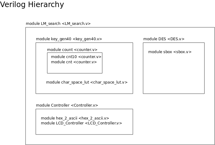
The diagram below shows all the Verilog modules and files laid out in a hierarchy.