High Level Design
Rationale
Depth detection is a technique that extracts depth information of objects in a scene, with applications in robot vision, automated vehicle control, 3D space mapping, and video games. Depth detection methods commonly employ stereovision, or vision through two cameras or “eyes.” Mimicking human vision, depth information is obtained from disparities in the two images obtained by the cameras.
With the recent surge in popularity of 3D televisions, 3D movies, 3D cameras, and video game peripherals like the Microsoft Kinect, we thought that depth detection would be an interesting feature to implement on the FPGAs used in this course. In particular, we wanted to implement a fully real time depth detection system taking advantage of the fast speeds and deterministic behavior of dedicated hardware. We found a paper by Georgoulas, et al., that implemented a real time disparity map computation module using a much more powerful FPGA running at 256 MHz. We based our design on the module described in the paper, but modified to run on the much less powerful FPGAs used in this course.
The most difficult part of acquiring a depth map is performing a fast and effective stereo matching algorithm. The three main approaches to this problem are 1) intensity-based, 2) image feature-based, or 3) phase correlation-based.(Murphy, et al., "Low-cost Stereo Vision") In an intensity-based approach, the intensities of corresponding pixels from each camera are compared. A rough disparity map is constructed from the minimum of the sum of absolute differences (SAD) in intensities. In a feature-based approach, the patterns and shapes of objects shown in the image array are used for comparison between the two cameras and a more simplified and accurate disparity map is computed. In a phase-correlated approach, we align the phase of a filtered image of one camera with another, and compute a disparity based on the phase shift. It is fairly robust for variations in lighting conditions, but can be computationally expensive. We are interested in a matching algorithm that is not limited to the objects detected on screen, and also requires a minimal amount of logic so that it can fit into our DE2 board. Therefore, we decided to use an intensity-based approach.
Most previous projects involved the use of some kind of Xilinx FPGA board, which contains a noticeably greater amount of combinational logic elements and ALUs than our DE2 Altera board. This gives us further motivation to use the simplest top-level architecture with the lightest amount of computation requirements. In the end of our literature review, we found the paper "Real-time Disparity Map Computation Module" (Georgoulas, et al.) to be the most promising and most ideal reference for the hardware resources that we have.
Background Math
The basic method of estimating the depth, or the distance between an object and the two cameras, is to look at the position of the object in a horizontal scan line in the two images captured by the cameras.
Before we go further, we will define the positions and the angle that the camera is pointing at. First, the cameras must be pointing at the exact same angle in the exact same orientation. Then, the only difference in the position of the cameras must be a finite horizontal translation in the plane perpendicular to the angle that the cameras are pointing at. There must be no vertical translation.
With this setup, an object that appears in the left camera will appear toward the right relative to the position of the object in the right camera. This is illustrated in the following figure, which shows a bird’s eye view of the two cameras positioned to look at a single object, represented as a black sphere.
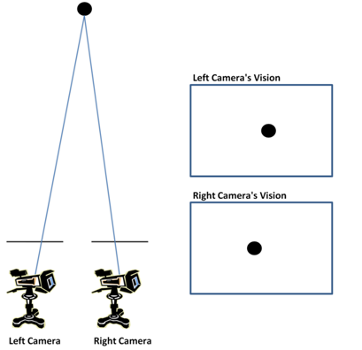
The horizontal bars above the cameras represent the frame of the image captured by each camera and are indicators of the fields of view of the cameras. The boxes at the right show the 2D images captured by the cameras. Note that the object is positioned slightly to the right in the image captured by the left camera compared to its position in the image captured by the right camera. Also note that the vertical positions of the object are the same in the two images, a result of the fact that the cameras are pointing at the same angle and are positioned in the same horizontal plane.
We now proceed to see what happens when the object is placed closer to the two cameras, as shown in the following figure.
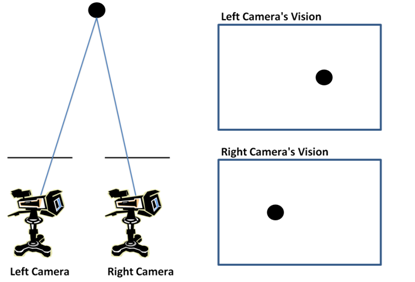
We see that the difference in the horizontal position of the object in the captured images increases. Thus, we can qualitatively say that the depth of an object increases as the difference in the horizontal positions of the object in the captured images decreases.
The object in the left camera’s vision is always to the right of the object in the right camera’s vision, regardless of where the object is located in the scene. This is illustrated in the following figure, which shows a red sphere and a blue sphere being captured by the cameras.
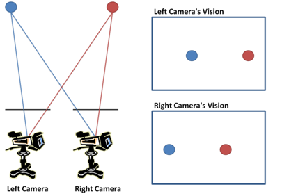
The blue sphere is at the edge of the field of view of the right camera, and the red sphere is at the edge of the field of view of the left camera. Note that both spheres in the left camera’s vision appear towards the right of the same sphere in the right camera’s vision. This property becomes important when designing the disparity calculation module for the FPGA.
Now that we have a qualitative understanding of depth detection, we will mathematically quantify this observation. First, we define the variables shown in the following figure.
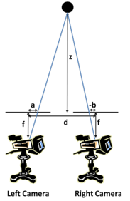
In the figure, “f” is the focal length of the cameras, “d” is the distance between the cameras, “z” is the depth of the object, “a” is the difference between the object’s horizontal position and the center of vision for the left camera, and “b” is the difference between the object’s horizontal position and the center of vision for the right camera. Note that “b” is negative because the object’s horizontal position is to the left of the center of vision of the right camera. Thus, “-b” in the figure is the positive absolute difference between the object’s horizontal position and the center of vision of the right camera.
From the diagram, we notice two pairs of similar triangles. The first pair of similar triangles consists of the triangle with “f” as the height and “a” as the base and the triangle with “z” as the height and a length we will call “a’” as the base. The second pair of similar triangles consists of the triangle with “f” as the height and “-b” as the base and a triangle with “z” as the height and a length we will call “b’” at the base. Then, we can use properties of similar triangles to obtain the following relations:
![]()
![]()
We can add the two equations together to obtain:
![]()
We can also relate “a’” and “b’” to “d”:
![]()
We plug this into the equation we have to obtain:
![]()
We then manipulate the equation to find the depth “z” as a function of the other variables:
![]()
![]()
Note the “z” was defined as the depth counting from distance “f” away from the cameras. Thus, the actual depth relative to the camera position is “z+f”:
![]()
We thus see that the depth is proportional to the inverse of the sum of “a” and “-b”, which is the distance between the two objects in the two cameras. Note that while we assumed the object is located between the two cameras, a similar sequence of steps can be used to show that the depth remains proportional to the inverse of the distance between the two object images in the two cameras when the object is located to the left of the left camera or to the right of the right camera.
Until now, we have assumed that there was nothing in the background, and that the cameras detect the objects as independent entities. In reality, cameras only capture pixel data and a pixel that is a part of the background is indiscernible from a pixel that is a part of the object. Furthermore, objects in the frame generally consist of many pixels. To apply the above algorithm to actual hardware, we must be able to detect objects from pixels.
One simple method to translate the above algorithm to actual hardware is called the intensity-based approach. In this approach, a small window of pixels in the first camera’s image is treated as an individual object, and a matching window of pixels is searched for in the second camera’s image. The match occurs for the window in the second camera’s image for which individual pixel intensities vary the least between the two windows. This is illustrated in the following figure, which shows a close-up of a 4x4 pixel window from the first camera and a matching 4x4 pixel window from the second camera.
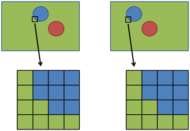
The difference between the horizontal position of the first camera’s window and the horizontal position of the second camera’s matching window is the disparity. We don’t vary the vertical position when searching for the matching window in the second camera, as we assume that objects appear with the same vertical position in both cameras. Also, since we know that the object in the second camera’s image appears to the left of the object in the first camera’s image, we only search for windows leftward. Realistically, there may be a pixel or two vertical position difference in the images captured by the two cameras; this adds some inaccuracy to the produced results. The disparity that we calculate here is considered to be the disparity of the pixel at the center of the window. To obtain a disparity map of the entire scene, we repeat the above window matching algorithm for every pixel in the frame. Once we have a disparity map, we can estimate the depth map because we have found that the depth is inversely proportional to the disparity.
Because it is very unlikely that for a particular window in the first camera, a perfectly matching window can be found in the second camera, we must be able to devise an algorithm to find the best match. To do this, the intensity value of each of the pixels in the first window is compared to the intensity value of the corresponding pixel in the second window, and the sum of the absolute intensity difference for every pixel in the window is obtained. The window for which this sum is smallest (i.e. the deviation in pixel intensities is least) is the best matching window.
Logical Structure
In this project, we connect two Terasic camera modules running Micron MT9M011 CMOS image sensors to the GPIO ports of a DE2 board. The input image streams from the two cameras are passed to temporary memory registers. The data from the temporary memory is used to compute a disparity/depth map in real time. Whenever a new pixel data arrives in the image stream, the disparity of that pixel is computed. The results are saved to the SRAM, which is concurrently read by the VGA controller to output a VGA image to a monitor.
Hardware/Software Tradeoffs
In designing the top-level structure, our goal was to parallelize the computation as much as possible while making sure the total number of logic elements does not exceed the maximum limit on the DE2 FPGA board. All of the disparity map computation must be done within each pixel cycle, so the computation must be fast. The parallelization schemes and top-level architecture from our reference paper were used.
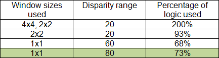
We started the implementation on a 640x480 pixel array and used as high as an 8-by-8 window sizes and a maximum disparity range of 80 pixels for disparity calculation, as specified from the reference paper. Due to logic limits, we were not able to incorporate all of the window sizes and disparity ranges which gave us the challenge to choose which parts of the high-level structure can be taken out. We attempted various combinations of window sizes and disparity ranges, and finally decided to use only a 1-by-1 window size and a disparity range of 80 pixels for our disparity map computation. A 2-by-2 window size fits within the limits of the DE2 board with a 20-pixel disparity range, but this range is not ideal for viewing depths in an average-sized room. Typically the disparity range must be between 60 and 100 so that objects close to the camera can be detected as well. As a result, we removed the local variation computation and window selection modules because we only had one window size to choose from. This also made our serpentine memory less logic heavy.
We tried make the computation as simple as possible, and always tried to reuse registers whenever we could. However, the main bottleneck lies within the logic demands for the disparity calculation, which cannot be altered. Therefore our best option was to decrease the window sizes and sacrifice the image quality. We also decreased the VGA screen resolution to 320x240 from 640x480.
Other Concerns
This project does not involve the use of any hazardous materials, and cannot be used for causing danger or human risk of any kind. Our project satisfies all of the IEEE Standards for Consumer Electronics and is in compliance with the IEEE Code of Ethics. This product is by no means a new idea, nor a sellable product. Therefore there is very little possibility for patent applications or publication.