Results
Video Output
From the color-mapped depth image, we were able to output disparity data at a rate of about 10 fps with 320x240 pixel resolution. The frame rate is computed as the clock frequency divided by the number of pixel clock cycles for one frame, as shown below:
![]()
Depth Map Quality
Our output images resulted in accurate representations of depth within a range of 0.5 to 2 meters away from the cameras. When an object moves close to the camera, the object is coated with a dark blue shade. As the object moves further away, the coating changes to navy blue, light blue, green, light green, and finally treated as part of the background. The shape of the objects can also be detected from our depth images. This means we can distinguish between various objects at various depths within the field of view range of both cameras.
When looking at the depth values of a detected image, the outer edges of the objects have correct values while the object’s interior has incorrect values. This is due to the fact that our algorithm is intensity-based so it can only distinguish between foreground of an image from one camera and background of an image from another camera. The depth is accurately depicted within a range of 0.5m to about 2m away from the camera using uniform light distribution emitted from a location close to the cameras.
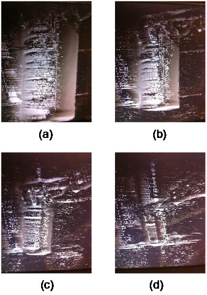
Figure 1: Four grayscale depth images of a cylindrical object at different depths. Image A) represents the object 6 inches away. Image B) represents the object 1 foot away. Image C) represents the object about 3 feet away. Image D) represents the object about 6 feet away.
From the series of images above, one can see that there is background noise caused from the output of the left camera. This noise is partly a consequence of the synchronization process between the two cameras. The noise in the left camera occurs along the edges of objects and in areas of highly-varying intensities.
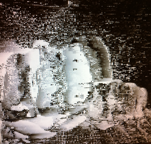
The following is another output image, showing two fists, one in front of the other. We see the front fist with a greater depth value (lighter color), and also see the texture of the fists resolved.
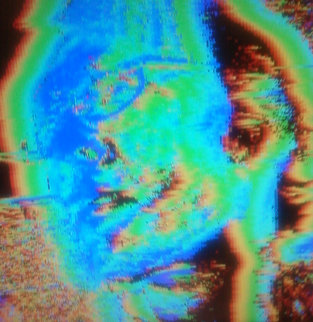
The following is the depth map of a spectacled face. The rim of the glasses is correctly resolved.
Ghosting Effect
We encountered a phenomenon in which the depth map produces a depth representation of an object and a similar depth representation to the left of the object. The distance between the two representations is directly proportional to the horizontal distance of the same object between images of the two cameras. Therefore, as the object is positioned closer to the camera, the ghost depth representation is further away from the original depth representation and is also more pronounced. This effect also differs between different object sizes and shapes. Objects with vertical contours, such as a vertical bar or a hand oriented upright, greatly expose this effect.
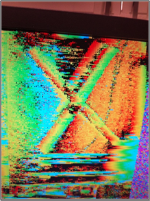
Ghosting occurs because of the fact that the pixels in the background of camera one show a positive disparity when the corresponding pixels in camera two are occluded by an object in camera two. This effect is shown below:
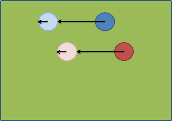
This figure shows the image in camera one, with objects shown in blue and red, overlaid with the corresponding image in camera two, with objects shown in light blue and light red. Four disparity values are shown as black arrows, where each arrows points to the pixel in the second camera image which has the smallest absolute difference. Thus, the length of each arrow is proportional to the disparity of the pixel that the arrow originates at. We see that for the pixels at the center of the objects in camera one, we have a disparity value equal to the distance between the object in camera one and the corresponding object in camera two. This is desirable. However, we also see that for pixels in the background of camera one, there is some small but positive disparity because the background in camera two is occluded by objects. The disparity is caused by the fact that the smallest absolute difference in pixel intensity occurs outside the objects in camera two, when the background becomes visible again. Thus, the intensity of the ghost image is a function of the size of the object that occludes the background in camera two.
Noise Removal Filter
We were able to apply the noise removal filter and observe a reduction in background noise, as seen in the figures below. However, due to the fact that noise removal is performed while the VGA controller is outputting the image to the screen, the screen flickered between images before the noise removal and after the noise removal. This could be remedied by adding a frame buffer so that the VGA controller could output one frame while the noise removal filter is applied to another frame. However, we did not have time to fully implement this feature.
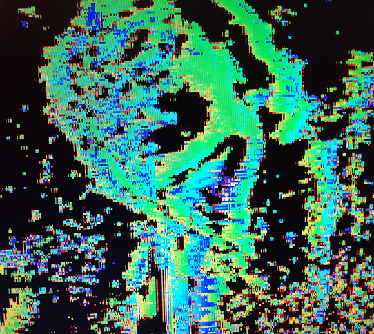
Figure 1: Image after noise filtering.
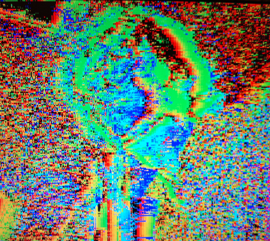
Figure 2: Image before noise filtering.
Camera Synchronization
We were able to consistently keep the pixel outputs from each camera synchronized with respect to row and column of the image raster. Sometimes the lighting environment causes a significant column offset, but after repositioning the cameras the column number is synchronized again.