"A video game enhancing system using various distortion visual effects on 2-player split screen games"
The objective of this project was to design and implement a video game enhancing system on an FPGA. Our implementation partitions the video signal of a standard 2-player split screen game to two VGA signals, each which only display a single player's half of the screen. Each player is allowed to select 1 of 8 different video "effects" to use on their opponent periodically.
For the purposes of our project we customized our system for the Halo series on Xbox 360. The majority of our visual effects can be used on most first-person shooters and other split screen games.
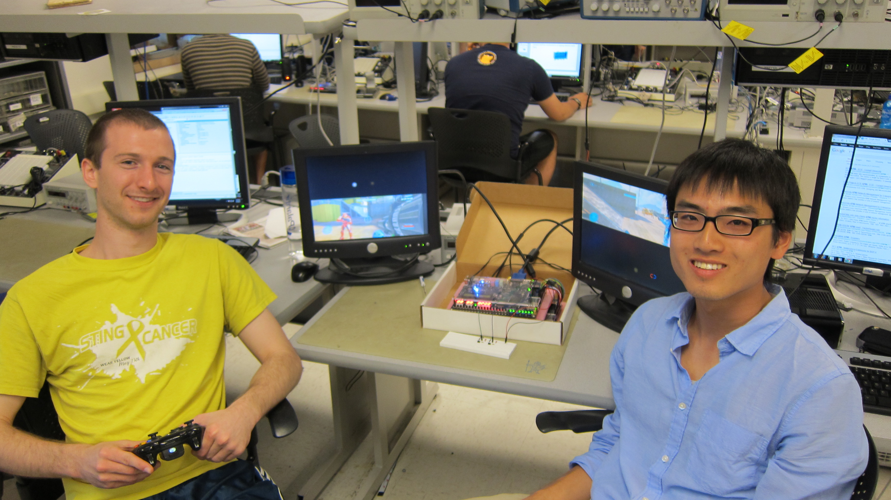
Scott Warren (left) and Adam Shih (right)
Video demonstration.
High Level Design
Rationale and Inspiration
After spending the majority of the semester working on FPGA projects that output a VGA signal to screen, we wanted to build a system which capitalized on that experience. In addition, we wanted to base our project idea around some sort of game. With those two thoughts in mind, we originally considered developing our own simple first-person shooter game. In the end, we decided that we wouldn't be able to utilize FPGA potential enough under our time constraint, and chose to implement a system which enhanced a game or games we both enjoy to play (and could play against each other).
The motivation for this project was to create a system that could be complementary to existing split screen games, and would essentially enhance a player's experience. Our hope was to be able to add effects and power-ups that visually distort an opponent's view and in doing so would add novels elements to existing games.
Logical Structure
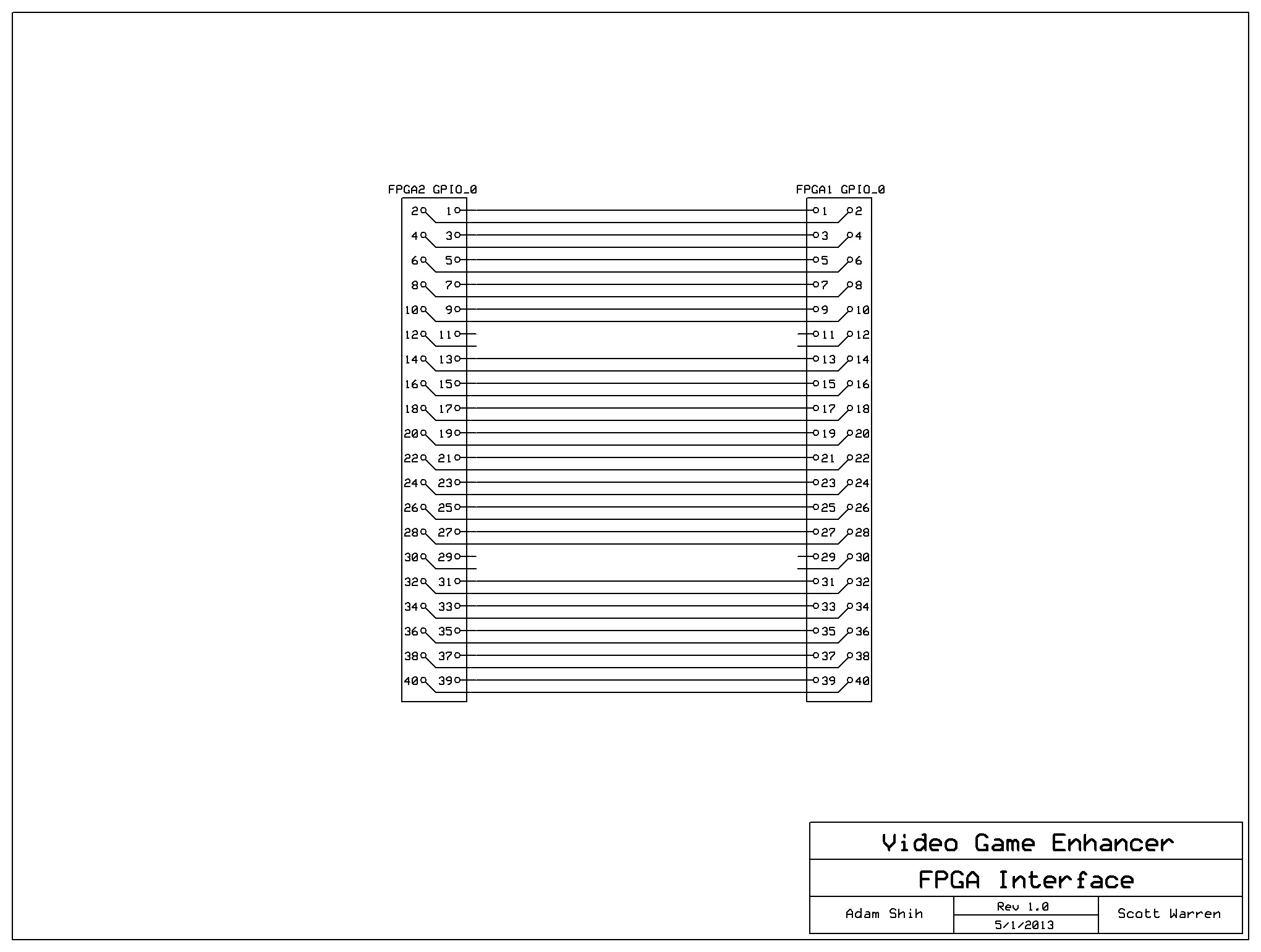
At a high-level, our design consists of two DE2 boards, but we really only use one of the two FPGAs. The first serves as the primary controller, and essentially does all the computation necessary in our implementation. NTSC video signal is taken as an input into the primary DE2 board. The FPGA on the board also listens to designated GPIO pins connected to external buttons added for effect usage. Once a player pushes his/her button to select or use an effect, the primary FPGA updates the player's screen accordingly through VGA signal output. The primary FPGA also sends VGA data across the GPIO pins to the secondary DE2 board, which utilizes it to drive a second VGA monitor. The second DE2 board is only used for its VGA output capabilities. No computation is done on the second FPGA.

High-level block diagram
Standards
Our project requires NTSC video standard signal as input (coming from a game console). Additionally, we output data as a VGA signal. As such, we must consider both television and computer display standards. Interfacing with these standards is aided with the reference to Altera's DE2_TV example (explained in Hardware Design).
Hardware Design
Overview
The physical hardware we used as part of our video game enhancer mainly consists of two Altera DE2 development boards. In addition, we also use 40 jumpers (for communication between the boards), two external push buttons, and two VGA cables plus two LCD computer monitors. Custom hardware is designed on the two on-board Cyclone II FPGAs in Verilog. Custom hardware design and other relevant components are detailed more below.

The physical hardware we used in our project
Top Level Module
The block diagram for our FPGA hardware design (what's inside of the primary FPGA) is shown below. We built our design off of the DE2 TV example provided by Altera as one of the demonstrations on the DE2 board CD. That hardware is explained in the next section. Our hardware sits between DE2_TV and the VGA output. We basically take the pixels that the DE2_TV monitor thinks it's displaying on the screen, manipulate them, and then drive two VGA monitors.
The RGB data from the DE2_TV module is streamed into the 5-line buffer to provide the delay needed for some of our effects. Each line in turn is sent through shift registers. When combined this creates a 6x9 matrix that moves through the pixel data at video rate. Each video effect module takes all or part of the matrix to work on. All the effect modules output the new pixel value which goes through two muxes. Each of these muxes select out the appropriate effect pixel to use (or the original if no effect is in use) based on the control signals from the icon modules. These icon modules are discussed in detail below. Each screen's pixel goes through one final mux which selects off of the value of the VGA Controller's Y coordinate. This is what displays the icons in one half of the screen and the game video in the other half. One of these pixel streams is sent to the VGA DAC on the DE2 board and the other goes out the GPIO pins to the other DE2 which simply sends that data straight to its own VGA DAC.
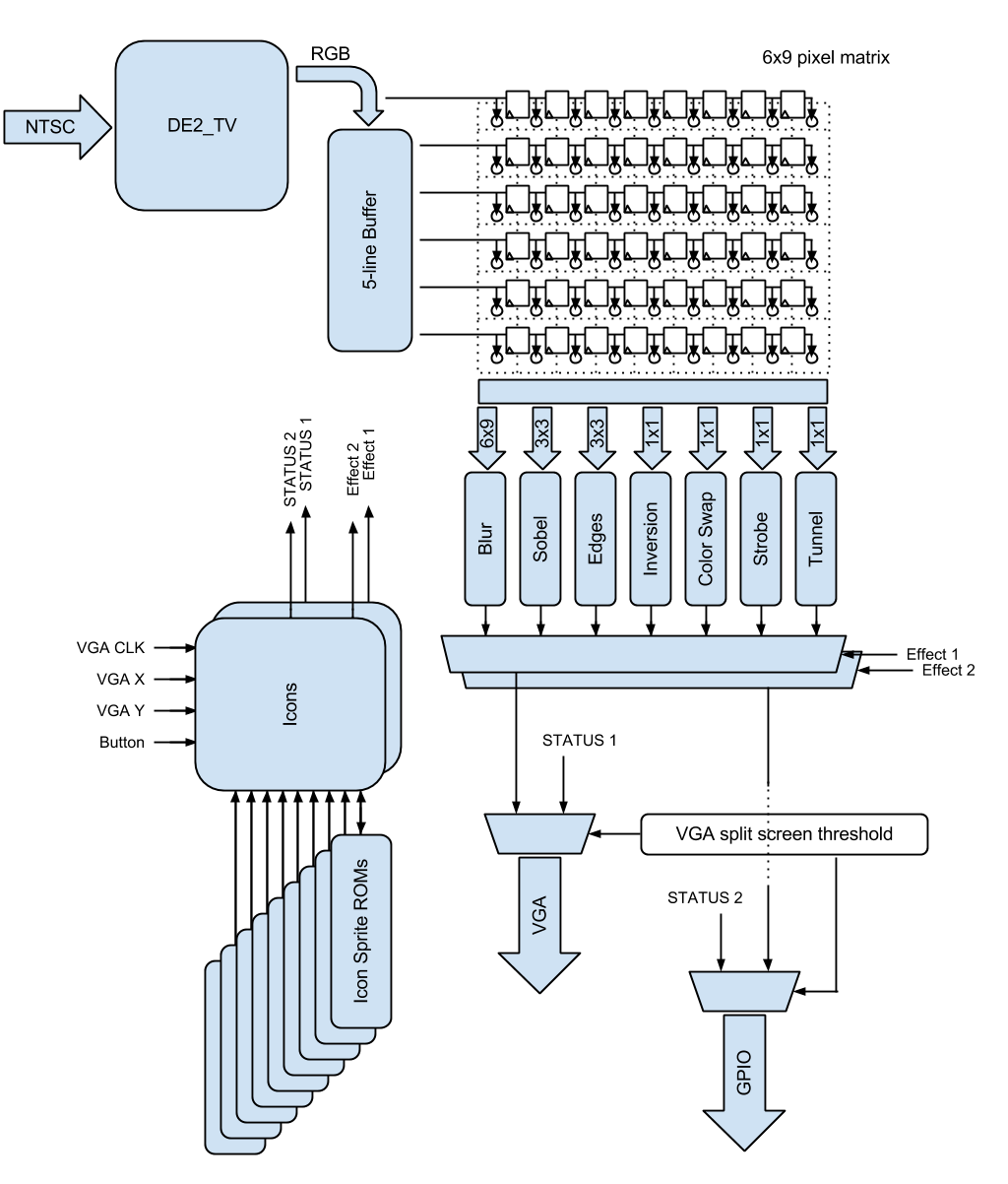
Top level FPGA logic block diagram
DE2_TV Example
Our design is based off of the DE2 TV example provided by Altera. This example takes an NTSC signal and converts it for display on a VGA monitor. Shown below is the block diagram. The system works by setting up the TV decoder, then streaming the data from there through a second decoder to convert to YUV 4:2:2 color space. This passes its data into an SDRAM frame buffer which is necessary because of the interlacing done by NTSC. The frames are read out from SDRAM a line at a time with even and odd frames changing every line to interleave the entire picture back together. This data is then goes through two more color space converters. First from YUV 4:2:2 to YUV 4:4:4, then from there to RGB which is necessary for display on the VGA. The VGA controller then takes the RGB data and generates the appropriate signals to drive the VGA monitor.
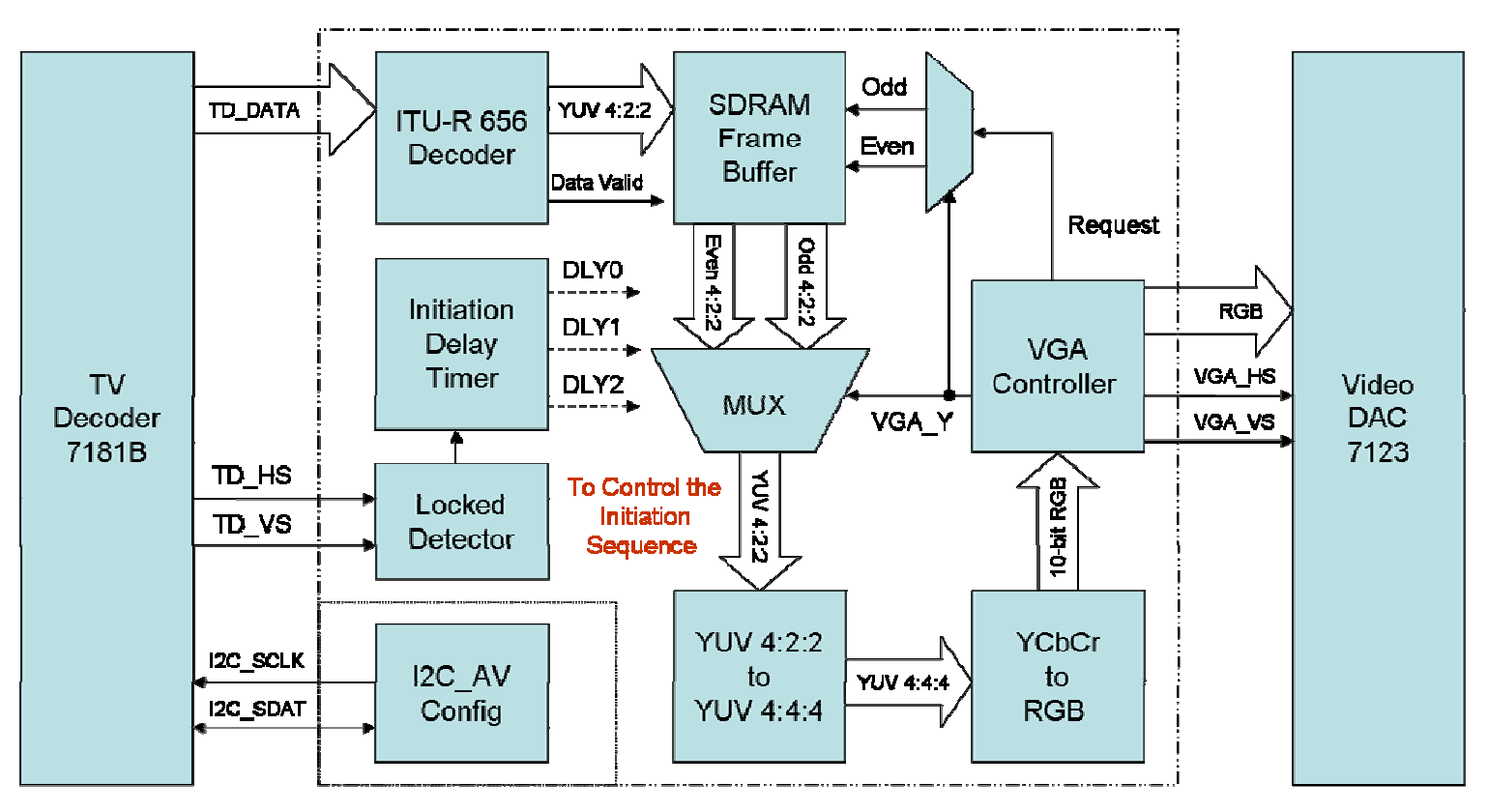
DE2_TV block diagram
Icons
This module controls the display and use of the various effects. Its inputs include the VGA coordinates, the buttons, and the pixel data from the icon sprite ROMs. It controls these ROMs through output addresses. As there are two icon modules the addresses into the ROMs are buffered by a mux that gives control based on which half of the screen is currently being worked on. This module also outputs the current effect, if it's been enabled, and the data for the pixel that should be displayed (the icons). These pixels are chosen based off of the current coordinates. We section off the screen into 8 squares. When in one of these squares we choose the appropriate pixel from the icon sprite ROMs and increment the appropriate address. When not in a square we simply output a black pixel value.
Show below is the state machine diagram for the icons module. It resets to the choosing state. In this state the icons are displayed one at a time for 4 frames each in a roulette style. When the player presses the button it transitions to the debounce state and holds the current effect value. The debounce state simply waits until the button has not been pressed for a certain time. This is to prevent any bouncing of the switch causing a second unwanted button press. Once it's sure the button is release it goes into the ready state. Here we just wait for another button press. During this time the selected effect will be statically shown on the player's screen. When the player presses the button again we go into a counting state. This simply counts out time, to 10 seconds, while the effect is being displayed. Afterwards we go into a delay state that again counts to 10 seconds, but in this state the effect is no longer enabled. This was done to give the other player a break so their screen isn't constantly being affected. After delay we go back to choosing and the process starts over.
Icons state machine
5-line Buffer
In order to store enough pixel data to perform image filtering on each video frame, we use a 5-line Buffer for use in convolution techniques. We utilize the Altera Megafunction ALTSHIFT_TAPS, which is a RAM-based shift register. Our 5-line buffer uses M4K blocks with taps on each line (with tap distance 640 for the screen width). Shift-in and shift-out width is 34 bits to accommodate 10-bit color channel RGB encoding plus VGA signal data (horizontal sync, vertical sync, etc.). The size of this line buffer allows the video game to perform a 6x6 convolution (later sections show we increase the horizontal size of this matrix up to 9x6 for better visual performance). Most of our filters only use a 3x3 matrix, but the more the better for the blur filter so we just made it as large as we could given the limited number of M4k blocks on the Cyclone II.
Visual effects
Our video game enhancer involves visually altering the video input of a video game, and as such our design features eight different visual effects implemented with custom hardware. The main objective of these effects is to visually distort your opponents view on their LCD monitor such to distract him/her and reduce his/her ability to effectively play the game.
Blur
The first visual effect involves using a 9x6 custom matrix to create a blurring effect on a player's screen. Typically, blurring matrices involve the averaging of pixel values surrounding the center pixel, and updating that center value. For our blurring matrix, we use a 9x6 matrix that takes the outer most values on the matrix along with six central values and averages them. Rationale behind using this particular matrix includes better performance (extended matrix from 6x6 to 9x6), more pixel variation (using further pixel values from the center), and more efficient averaging (32 "1" values in the matrix allow for logical shifts rather than division). The matrix shown below uses the 5-line buffer to store required data and effectively convolve over the screen image, pixel by pixel, to display on screen.

9x6 matrix for blurring
Edge Detection
The second visual effect uses a Sobel operator to detect the edges in each video frame. The full operation involves convolving two 3x3 kernels with the image of interest to approximate horizontal and vertical derivatives. To do this, we convolve the x-direction and y-direction kernels (shown below) with the sum of a video frame's RGB components and take the sum of the squares of both convolution products in order to produce the gradient magnitude. Our implementation uses the megafunction ALTSQUARE to compute the square of each convolution product. As a final step, we color all values that are over some empirically found threshold to green, while leaving all other pixels black to show only the edges.

3x3 Sobel matrices used for horizontal and vertical edge detection
Edge Enhancement
In addition to Sobel filtering, we use a second edge detection method. To detect edges in all directions, we convolve a 3x3 kernel consisting of center value of -8, and surrounding 1 values (shown below). Unlike with Sobel filtering, we convolve the kernel with each of the three RGB components rather than the sum. As a final step, we concatenate the altered components back in the correct sequence to produce the pixel value.

3x3 matrix used for secondary method of edge detection
Color Inversion
To complement visual effects that use convolution kernels, we also added effects that only operate on a single pixel to distort the color of the picture. To begin, we created a simple module to invert the RGB values for each pixel, essentially inverting the entire picture to its "negative". Our rationale behind this color distortion is to momentarily confuse a player that is looking for a certain colored object/opponent on the screen.
Red/Blue Swap
With the Halo games in mind, we created a fifth effect that specifically flips red and blue colors. The objective of this color flipping was to switch the colors of a red versus blue team game type, and as a result your allies appear to be your enemies and vice versa. For example, as a player on a red team, your allies are colored red and opponents blue. When the color flip effect is activated, your allies are suddenly colored blue, and your opponents red. To implement this, we exclude all green components and flip red and blue values for each pixel streamed in (green is omitted because of the small amounts of green in Halo's red and blue shades; this provides better color flipping in game).
Strobe Light
With five effects that already use image filtering techniques, we decided to add two visual effects that are based on blacking out opponents view in some way. The first of these is a strobe type effect that illuminates the screen image as normal for some small amount of time, then completely blacks out the screen for another small amount of time, periodically cycling through the image and a black screen for the duration of the effect. Our implementation uses a delay counter clock off of the frame rate, and displays a pixel normally if the count is below 8, or displays a black pixel if the count is above 8.
Tunnel Vision
The second blackout effect involves simulating tunnel vision. We implement this by simple displaying a black pixel if the current VGA X coordinate is outside the range of 200 and 440, else if it's within that range we display the actual pixel data. This creates a narrowing effect by eliminating side peripheral view by a width of 200 pixels on each side.
Screen Peek
Our eighth and final visual effect is different from the other seven because it does not involve distorting an opponent's screen, but rather enhancing yours. This effect restores the full screen that you would normally see when playing a split screen game, allowing you to "screen peek" and see where the other player is. The other player can however still use his effects on you to counteract this as the effects will work for both the top and bottom halves of your screen.
Screen Splitting
The screen splitting is done by simply changing the VGA signals going to each screen based off of the current Y coordinate of the VGA Controller. When it is above the threshold then one screen gets the converted input signal with any additional effects and the other screen gets the icon data. This is opposite for when the Y coordinate is below the threshold.
Game controls
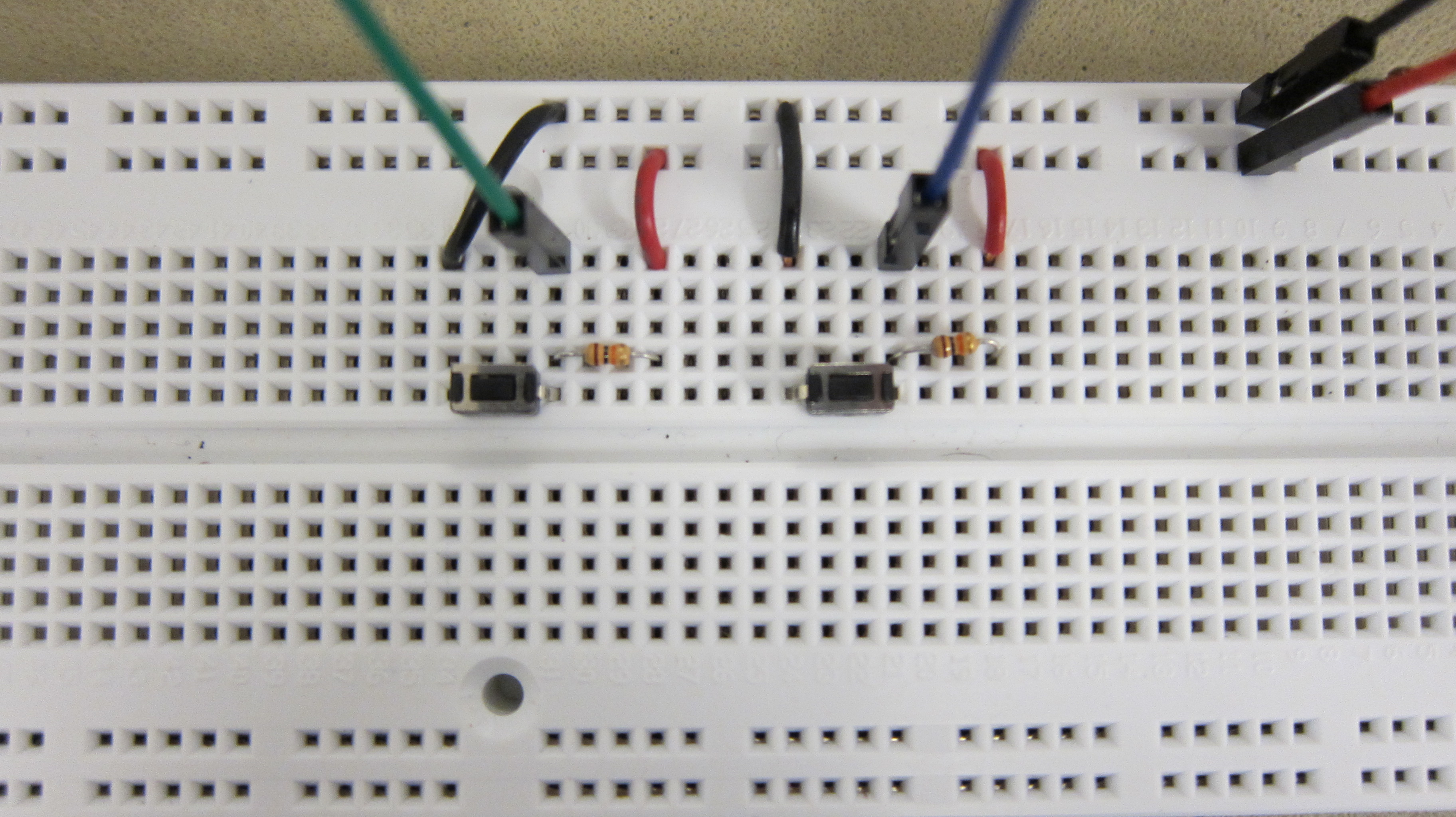
The physical buttons we use for input.
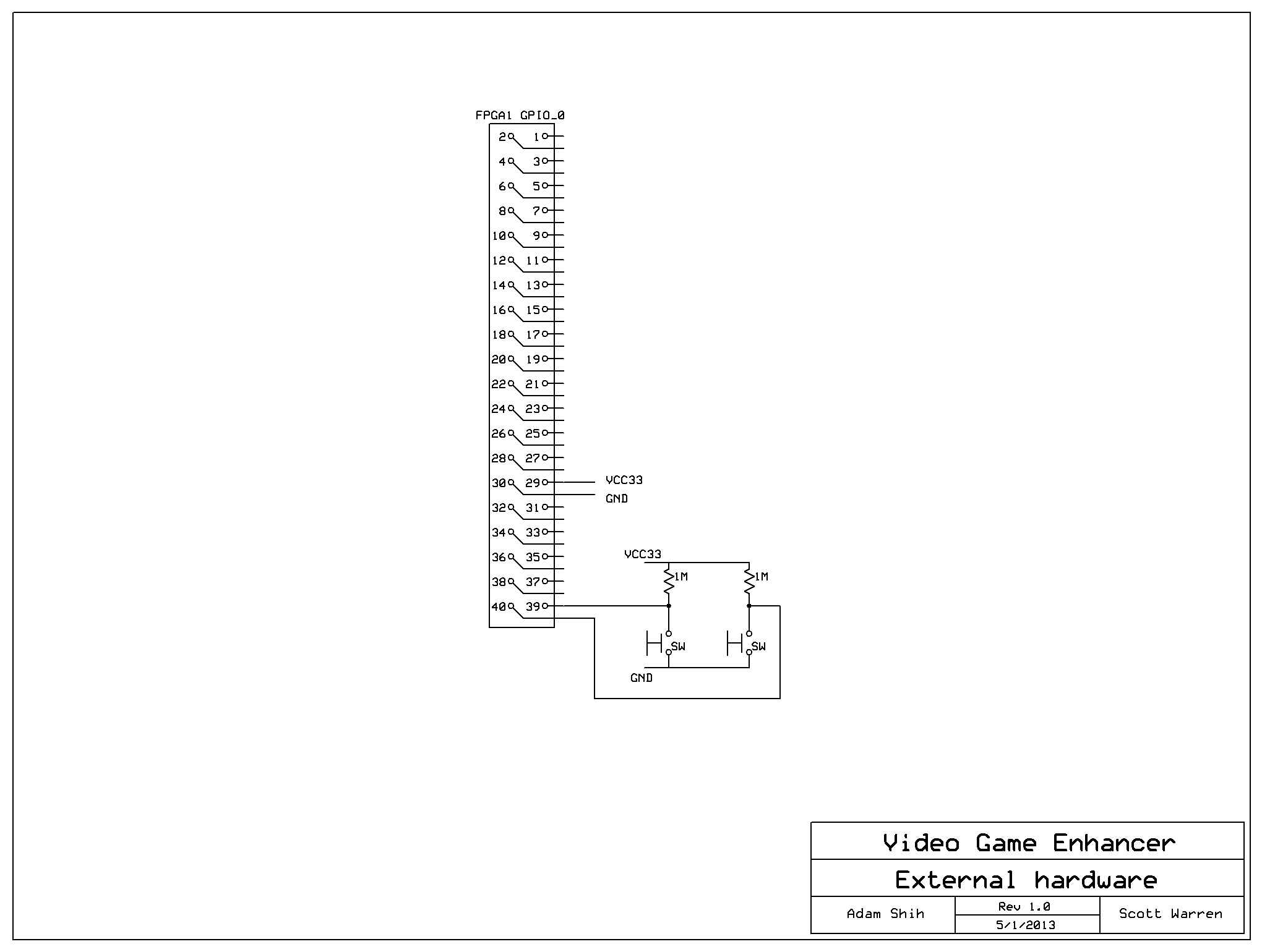
Our game is controlled through two buttons. There is one button per player. Pressing the button first halts the roulette of icons. Once an effect has been selected, pressing the button again will use that effect. Then there is a delay both as the effect is in use and after it has been used. When the roulette of icons shows up again this process starts over. Both of these buttons are connected to the second GPIO port. As seen in Appendix B, the button input is connected to VCC through a pull-up resistor. When the button is pushed it shorts the input to ground. We needed to add a small amount of additional hardware to properly debounce the switch.
ROM initialization and icons
In order to differentiate between different effects, we created unique icons to represent each individual one. Each icon was made as a 32x32 24-bit bitmap. To convert these .bmp files to .mif files required for ROM initialization, we wrote a Matlab script to format the file properly and output a memory initialization file (see Appendix A for .m script).
Eight 32x32 effect icons (blur, edge detection, edge enhancement, color inversion, red/blue swap, strobe light, tunnel vision, screen peek)
We use the megafunction ALTSYNCRAM to store our icon data in M4K blocks and initialize these with the .mif files.
Results and Analysis
Speed of Execution
The video game enhancer responds extremely fast in realtime with no noticeable delay. This makes sense, as the system performs at video rate and displays pixel data almost immediately after being streamed in (with the exception of the line buffer and conversion delays, which are both small fractions of a frame). During development, we tested the system's primary game functions and visual effects, and noted no perceivable delay.
Accuracy
The below images display each of our effects. Strobe is not included as it would be difficult to capture in a picture. As can be seen, all of our filters create the desired effect. The Halo game has many edges so our edge detection filter is very busy. We iterated through many different threshold values to find a good middle ground. There are minor distortions at the edges of the screen due to our convolution matrix implementation.

Screenshot of original video screen
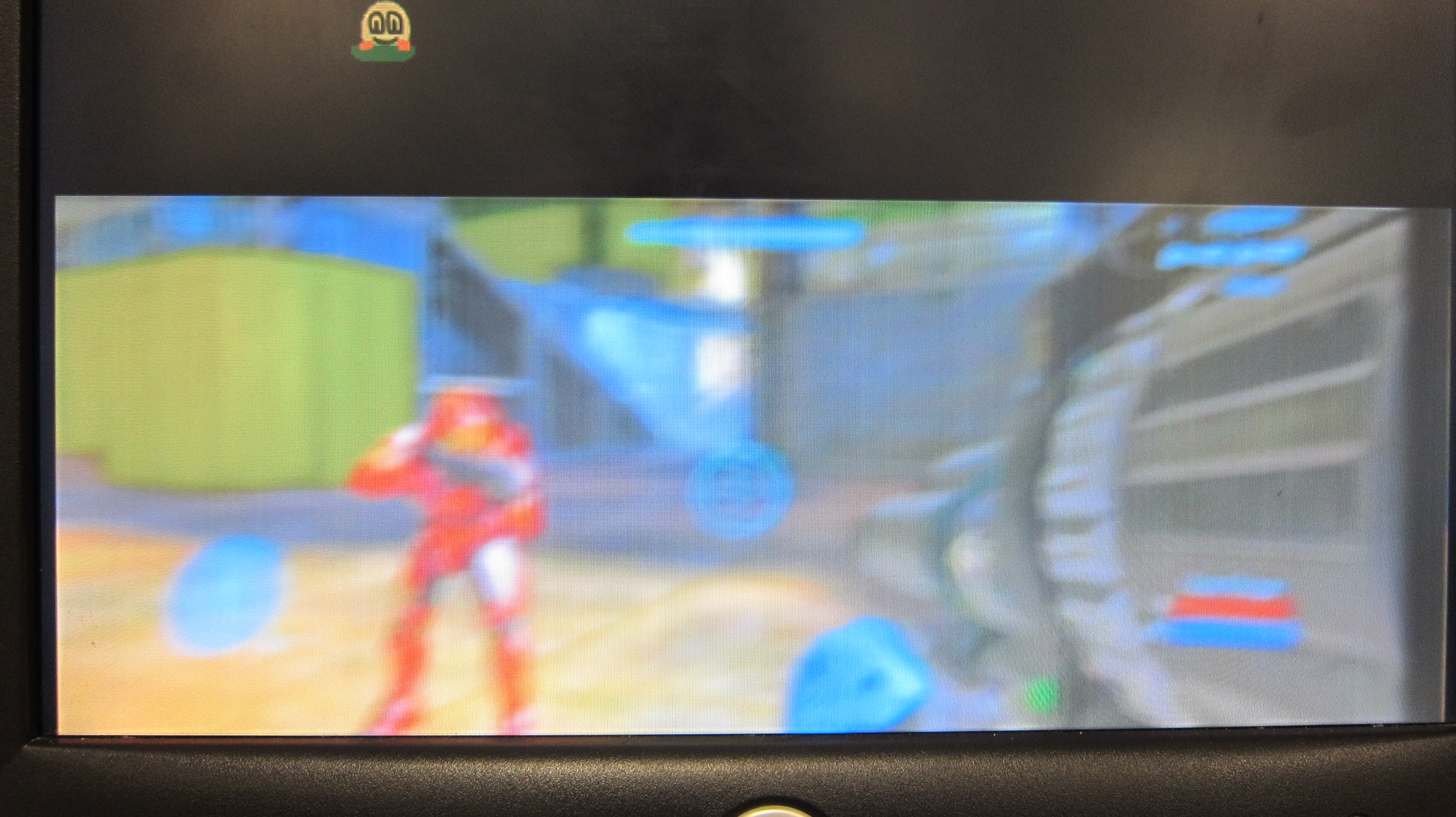
Screenshot of blurring effect
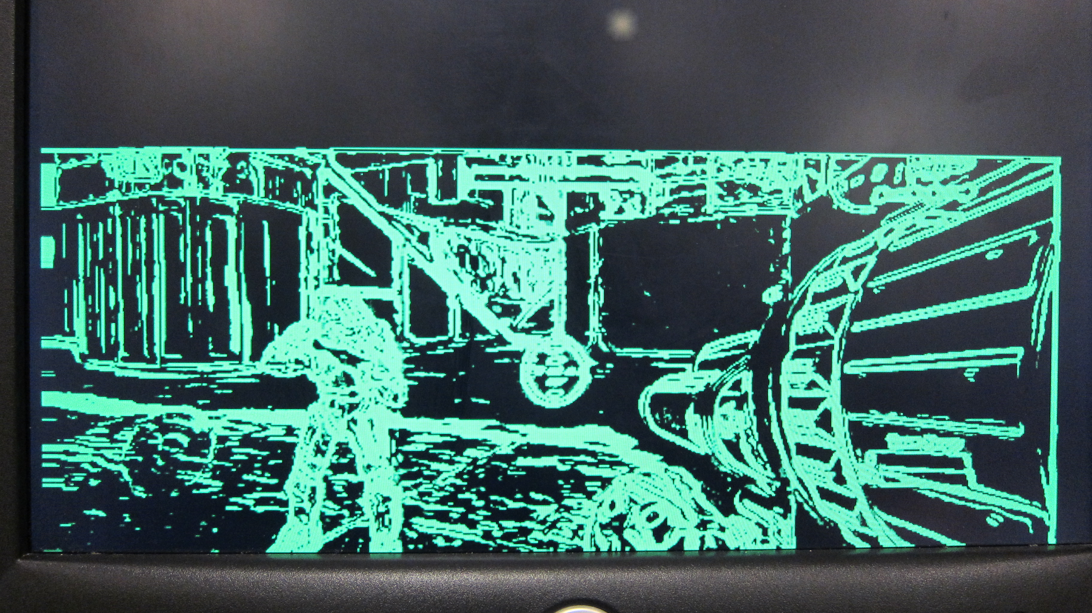
Screenshot of edge detection using Sobel filtering
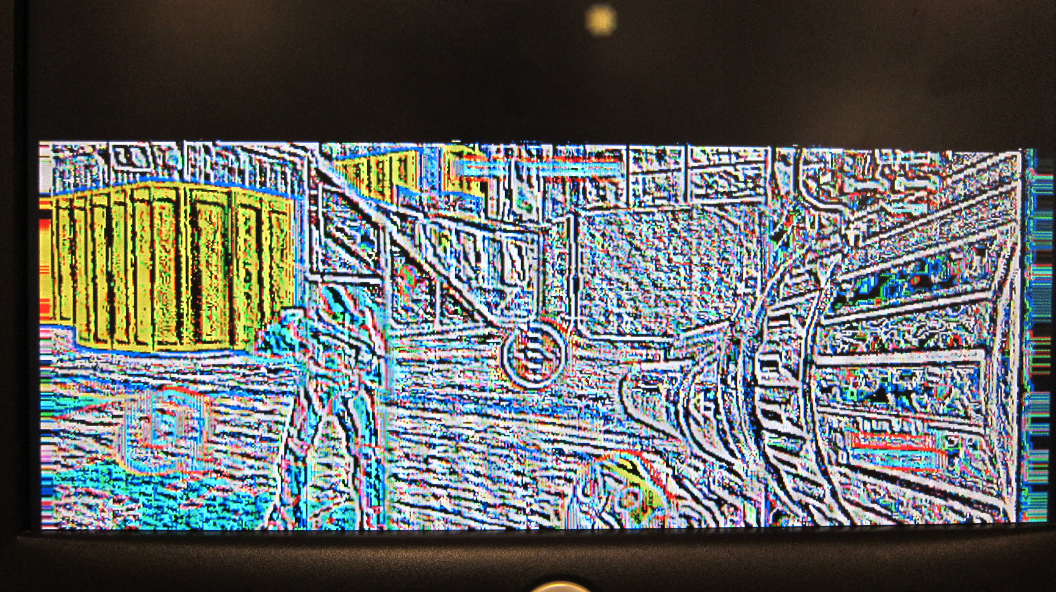
Screenshot of edge enhancement effect
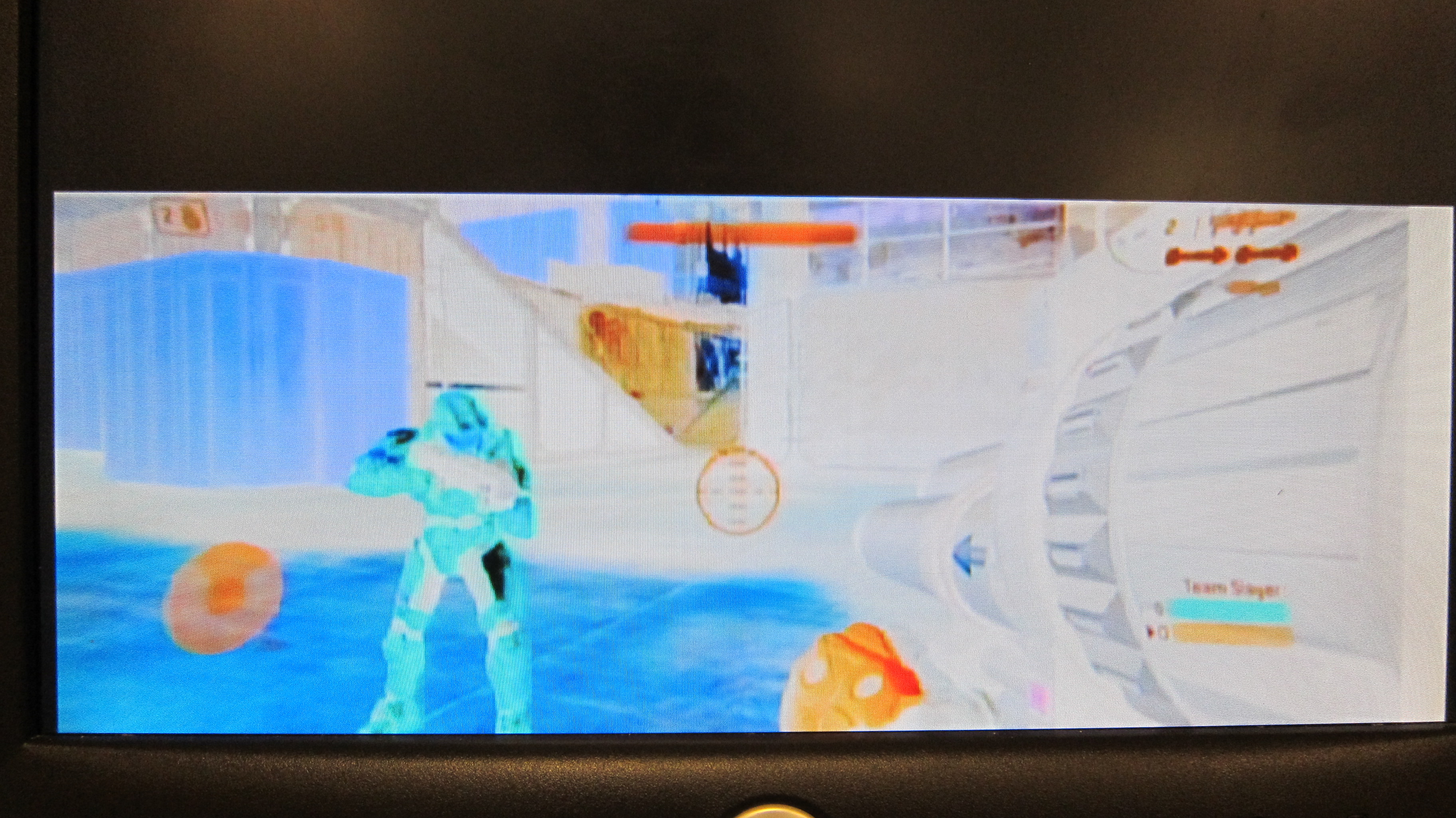
Screenshot of color inversion effect
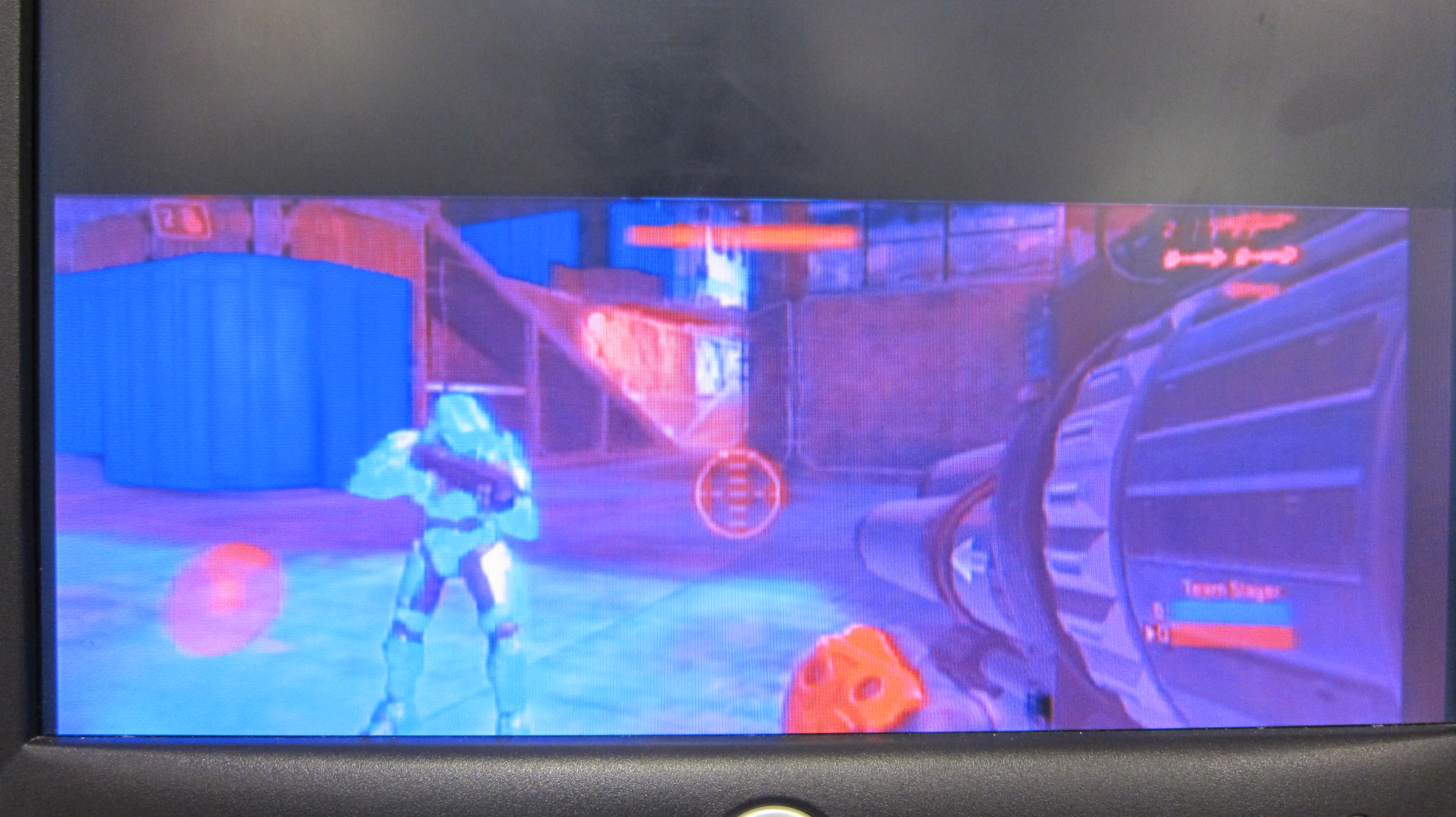
Screenshot of red/blue color flip effect
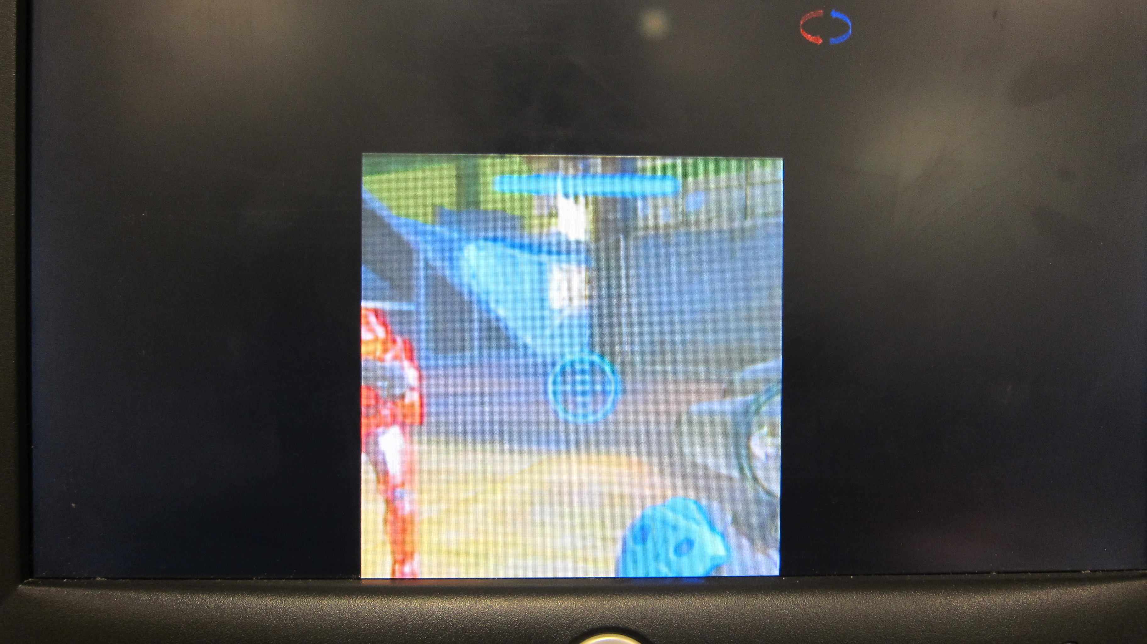
Screenshot of tunnel vision effect
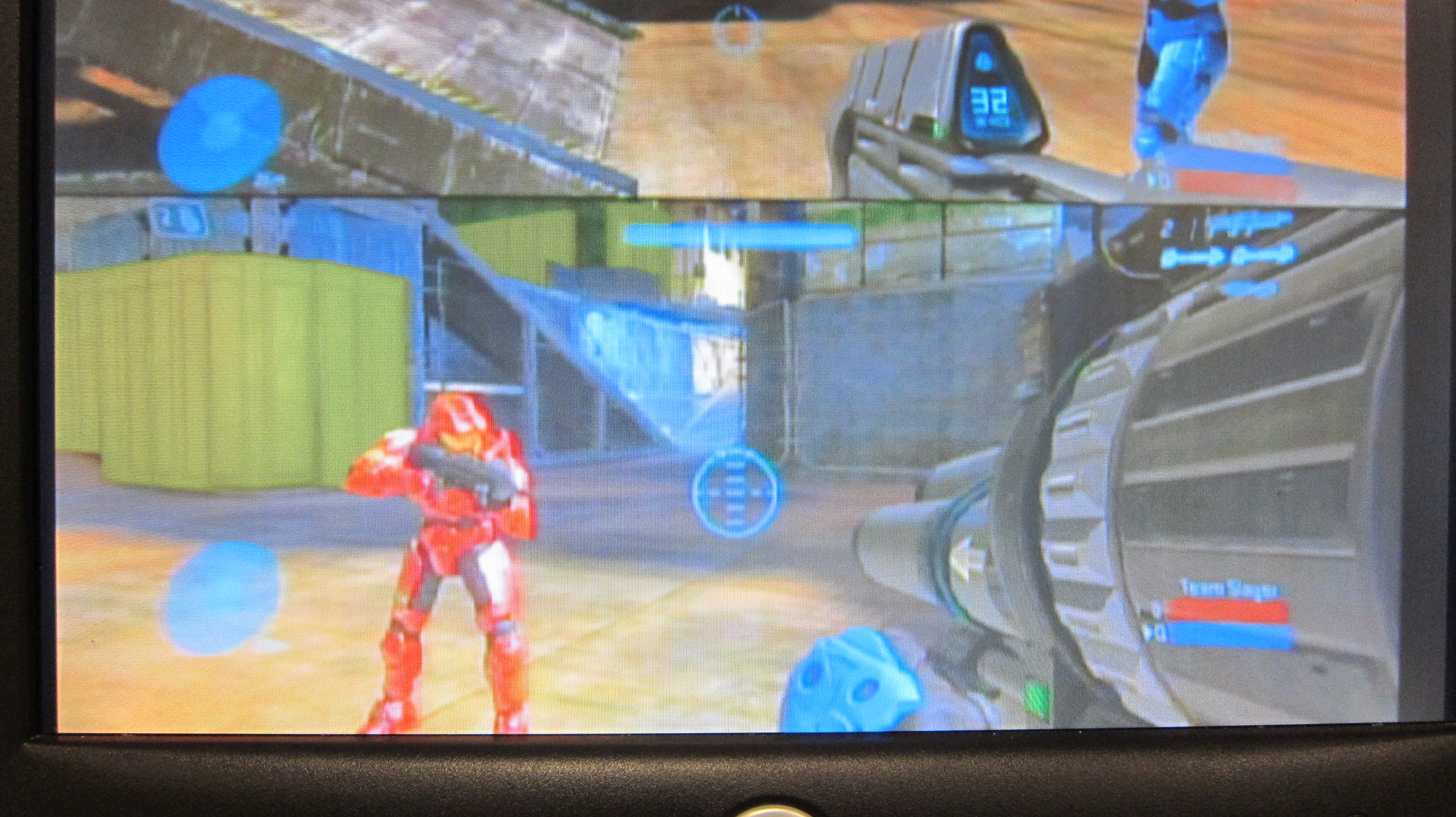
Screenshot of screen peek effect
Usability
Our video game enhancer is easily usable by anyone who has played 2-player split screen video games before. In a way, our game enhancer is a skin over the standard game and only adds one extra button (per player) that uses 1 of 8 effects - it's simply like having an extra button with one extra functionality. To increase usability during game start-menu and setup, we assign switch 17 on the main DE2 board to turn off screen splitting and blacking, and instead display the full video screen. Then when the players start the game they can just flip the switch back and resume the screen splitting functionality.
For project purposes, we kept the additional effect button on a protoboard with a stock pushbutton. However, with some customization, this button could easily be attached to a game controller by the connection of a longer, sturdier wire.
Safety
Due to the fact that we were using Altera DE2 development boards, there was little need to enforce safety. We ensure that all wire outs from GPIO pins are fully sheathed and that ESD foam is used between both DE2 boards, as they sit in close proximity to one another. When connecting the two DE2 boards together we also made sure not to connect the VCC's together or to ground.
We note that our strobe effect may not be ideal for those who are photosensitive and/or at risk of rapidly flashing images and lights. We took this into account while designing this effect, with the aim to make the periodic flashing slow enough as not to cause harm or discomfort. Without proper video game testing, it is difficult to say if our measures are effective. We make the assumption that if a player can play a standard Xbox game without negative effects, this slowed flashing should be reasonable as well.
Conclusions
Summary
Overall, the results of our project met our expectations at the beginning of the project. Our video game enhancer implementation successfully adds a novel element to 2-player split screen games using image filtering and other distorting effects. Additionally our project was able to successfully interface with both NTSC and VGA signal standards
In hindsight, if we were to redo this project, there would be a few aspects we'd try to improve upon. First, we'd be interested in outputting a NTSC signal rather than VGA signal. This would increase the usability of the device for practical everyday use in homes; it would allow players to use the same TV the normally would as opposed to a computer monitor. Second, we'd attempt to add any addition button hardware onto the video game controller directly, again, to improve usability in the real world. Lastly, we'd attempt to eliminate the need for a second DE2 board by purchasing and directly connecting the VGA DAC chip that is on the DE2 boards.
Intellectual Property
As mentioned earlier, our project uses Altera's DE2_TV example provided on CD with the DE2 board. Additionally, we used a few megafunctions from Quartus II to create custom hardware for use in our design. Aside from these exceptions, all code was written by us. No designs were reverse engineered in the process.
Legal Considerations
We do not own the rights to any games used or demoed with the video game enhancer. The video game enhancer serves our academic project as an interesting way to augment games we enjoy playing via the use of FPGA programming.
Appendices
A. Code Listing
- DE2_TOP.v
- blur.v
- sobel.v
- edges.v
- invert.v
- color_flip.v
- strobe.v
- tunnel.v
- icons.v
- delay.v
- create_mif.m
B. Schematics
FPGA Interface:
External hardware:
C. Distribution of Work
Scott
- Filters and effects
- Game controls
- Screen splitting
Adam
- Filters and effects
- Effect icons
- Project website
References
Below are links to external documents, code, and websites referenced and used throughout this project.
References
Acknowledgements
We would like to thank Altera for their example code and donation of DE2 boards to Cornell. We would also like to thank our instructor Bruce Land for the assistance and advice he provided towards this project, and of course for all the valuable discussion during lab (including topics both related and unrelated to lab).

