
Ankur, Bruce, Sai and Ackerley.
Introduction
"An FPGA setup which plays Flappy Bird automatically."
- Project Sound Bite

Flappy Bird is a recent popular game available on iOS and Android platforms. The game features a bird, which ascends when tapped on the screen and descends otherwise. The aim of the game is to navigate through the green pipes. For each set of pipes the bird passes, the player scores one point. The game has been recognized as one of the most addictive games of 2014. Our project is an attempt to make the Altera DE2-115 play the game on an Android phone. A camera provides video feed to the DE2-115. Based on this video feed, the FPGA identifies the position of a few key points on the screen, and based on these points, the FPGA decides whether or not to 'tap' on the screen via a GPIO output pin.
High Level Design
Rationale and Source of Our Project Idea
We were observing this game being played, and found that the key to getting past the pipes was being stable about tapping to keep the bird around a certain vertical threshold, relative to the pipes. This stability, constant focus and consistent decision making is very difficult for a human player, but would be trivial for a computer. Hence, we decided that if we could program a computer to observe the screen quickly enough, it could make very good decisions and be a very good Flappy Bird player. Such a task is well suited for the FPGA because it has plenty of power for parallel computation, as well as IO ports, that can process large amounts of data quickly. Hence, we embarked on this project
Background Math
Apart from basic addition and subtraction, there was no background math involved in this project.
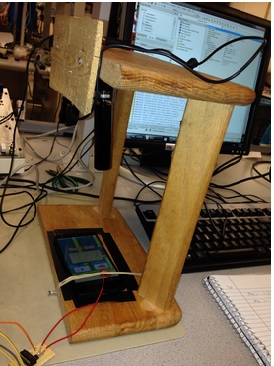
Physical Setup
The physical setup consists of a wooden frame, used to hold the camera a distance above the phone. The height of the camera mount is chosen such that it is perfectly aligned to capture exactly the screen of the phone placed at the bottom of the wooden frame as shown in the image.
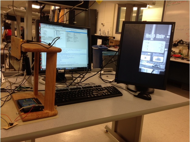
Full system setup
The taps on the phone are made using the coin, which is held on the phone's screen using a rubber band. The rubber band is held in place by stringing it between two screws, attached on both sides of the wooden frame. An aluminium plate is taped below the phone screen which is used as ground plate for the tapping mechanism.
The DE2-115 is connected to the VGA monitor which displays the game, the detection points and lines used by the game, for debugging purposes.
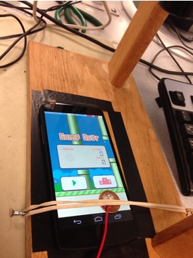
Game in Progress
Logical Structure
The Flappy Bird Player could be divided into four major components:
- The camera
- Compute unit
- Tapping hardware
- VGA display for debugging
A major difficulty in this project is having to bridge different clock frequencies. In our hardware setup, we used 2 different clocks, which are the 27 MHz clock for both the camera and the VGA display, and the 50 MHz clock for computation.
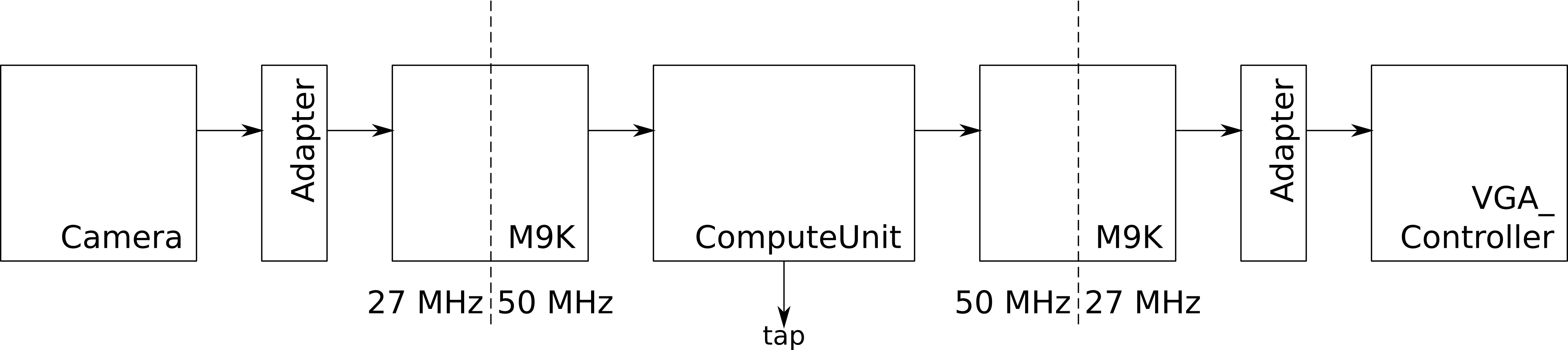
Flow of Data Through Main Components in Hardware
The above diagram shows how data flows in our hardware, through different modules. To manage the different clock domains without glitching on the screen, we chose to use M9K blocks to cleanly separate clock domains, since M9Ks can be set up with true dual-ports, with two different clocks on both sides. Hence, we had two sets of M9K blocks instantiated. The camera unit writes to one M9K block, and on the other side, the compute unit handles not only computation, but copying from one M9K block to the other M9K block. The second M9K block functions as a buffer for the VGA controller. This M9K block is written on one side by the ComputeUnit, and is read from the other side by the VGA controller.
We had to make a couple of optimizations in terms of memory to have enough M9K blocks on the Cyclone IV chip for display data.
Firstly, we did not store all pixels that were recorded by the camera. Instead, we only picked the relevant 512 x 256 pixels. We picked this resolution because the phone has a screen ratio of approximately 2:1.
Secondly, we only stored luminance information, so the internal image is in grayscale instead of color. We found this to be sufficient for edge detection and hence sufficient for our project.
The Camera
The purpose of the camera is to act as the eyes for the FPGA. For this project, we used a XO Vision HTC 231x CCD Bullet Camera. This camera was connected to the DE2-115 board via the TV decoder port using a standard RCA cable.
The DE2-115 has a Analog Devices ADV7180 TV decoder chip on-board. This TV decoder is configured using the I2C bus on reset. The I2C address of this TV decoder chip is 0x40, and is configured using the module I2C_AV_Config.
The camera set-up was modified from the Altera DE2-115 sample code for the TV decoder, which also came with an audio output module. In the interest of time, we left the I2C_AV_Config module mostly unmodified, other than comments. (The code contains labels for every line of TV decoder configuration, if you wish to use this module, this should help you).
The ITU_656_Decoder module interprets the signals from the TV Decoder hardware and translates them to pixels in x and y coordinates. This module was modified from the one provided in the sample code.
The key modifications made to this module was fixing of the oTV_Y output. The sample code provided oTV_Y, but that was not the actual y coordinate of the output pixel, because the TV Decoder decodes alternate lines of pixels (interlaced video). The decoder therefore had to be modified such that the y coordinate outputs are the actual ones interpreted by the camera, so that the internal image is not squashed.
The other modifications done were outputting the FVAL signal and the Field signal. We experimented with using these values to determine when to perform calculations, since these values suggested the validity of the TV Decoder data, but eventually did not use these signals.
This module outputs data in the YUV format, and we only used the luminance, or Y values.
Decoder to M9K Adapter
Since we are only using a subset of the pixels being output from the ITU_656_Decoder module, the M9K addresses have fewer bits than is output from the ITU_656_Decoder module, and so we use this adapter to select a subset of the bits, and to transfer the write enable signal from the ITU_656_Decoder module to the M9K block appropriately.
The write enable signal is only transferred over to the M9K block when the addresses are within the range of valid values. This module is also used to select the portion of pixels from the camera that we wish to display. This camera distorts the input image at the edges, and hence it would be ideal to select pixels in the middle part of all the pixels that the camera is able to record. Selection of pixels was done through trial and error, by using switches as the offset and using the switches to find the correct set of pixels to show.
Camera side M9K block
The camera side M9K block is the big block of memory which contains all the information of the video input. The M9K block is created using the in-built Megawizard Plugin manager of Quartus. The block is a true dual ported block of memory which can be be written and read at the same time using the two different data and address lines. The write operations from the decoder is done at the slower 27 MHz clock while the read operations on the compute unit side is done at the faster 50 MHz clock.
Each address in memory contains the 8 bit pixel information of each of the 512 x 256 (131072) locations on the screen. The address is 17 bits wide, which basically contains the Y and X coordinates of each point.
ComputeUnit
ComputeUnit is the unit in which all the computations of the project is done. It consists of different modules, for detecting the pipes for the bird to cross, as well as to determine when to send the tap signal to the phone. The compute unit takes in data from the M9K block, processes it, and then sends the processed information back to the M9K for display on the VGA as well as to the TapOrNot module to decide whether to tap or not.
This is the core of our project and will be elaborated on in the hardware section
VGA side M9K block
This M9K block is acts as a buffer for the VGA controller. The Copier (part of ComputeUnit) copies the contents of the camera side M9K block over to this M9K block at 50 MHz, and the VGA controller reads this M9K block at 27 MHz out the other side for display on the monitor
M9K to VGA Adapter
The VGA controller that we used was taken from lab 4, and was a generic VGA_Controller. Since we are only displaying 512 x 256 pixels out of the 640 x 480 pixels that this VGA controller can handle, this adapter is used to send the VGA_Controller gray pixels for those pixels not within the display range. In addition, this adapter also takes other debug inputs, such as inputs that show the detected positions of the bird and pipes, as well as line positions as debugging outputs.
VGA Display
The VGA module on the output side was mainly used for debugging purposes. The VGA monitor is used to constantly display the data that the camera takes in. It is essentially the data processed by the camera and passed along on to the compute unit. The VGA monitor is also used to display the top of the bird, edge of the pipe and also the top of the pipe. These points are displayed as crosses. The monitor also displays the threshold line which is basically a user-set threshold before the first pipe is 'seen' and the center of the gap between the pipes once the pipes are seen.
Tapping Hardware
In this project, we wanted to find a way of 'tapping' on the screen without having to build anything with moving parts. The main reason for this was that with our limited resources, it would be difficult to build anything with moving parts that could be fast enough to respond to tap signals, and at the same time be reliable enough for consistent tapping. Hence, we opted for an electronic approach that fit in better with the use of the FPGA.
Tapping Hardware
We began with the idea of using the Android Debug Bridge (ADB) to trigger touches on the Android phone. The advantage of this is that ADB works over a USB connection, and hence the camera would have an unobstructed view of the full mobile phone screen, which would make detection of key points on the mobile more reliable. However, we did some preliminary tests by sending ADB commands over to the phone from a computer and found that even at the maximum ADB transfer speed, we were unable to keep the bird in the air until the first pipe. As such, we moved on to use a hardware approach to tapping on the screen.
The mobile phone and its touch screen interface is an extremely interesting piece of hardware. We do not profess to have a complete understanding of how the touch screen interface works, but this is what we gather from online sources and from experimenting with the mobile phone. Most modern mobile phones have capacitive touch screens, which use a layer of capacitive material to hold an electrical charge. When we touch the screen, the capacitance of the surface changes, and the phone is able to detect the change in capacitance.
The phone performs some kind of comparison between the charge on the touch screen and the electrical ground of the phone.
We explored two ways of tricking the phone into doing this comparison. Firstly, as mentioned in this forum thread, we could access the ground on the phone through the phone's 3.5 mm earphone jack. A piece of conductive material, in contact with the phone's touch screen, will trigger a 'touch' if it was shorted to the ground pin of the phone's 3.5 mm earphone jack.
A second way of doing this comparison is through the back of the phone. When people use the phone, they tend to hold it in one hand and tap on the screen with the other, and this forms a conductive loop between the finger, tapping on the screen, and the back of the phone, which the phone somehow uses to determine taps. By shorting a conductive material in contact with the phone's touch screen with a conductive material in contact with the back of the phone, 'taps' can also be triggered on the phone. This method was inspired by this video. We eventually selected this method as it was less 'invasive'. We were uncomfortable with connecting to the 3.5 mm jack of the phone in case any wiring mistakes cause our phone to malfunction.
We experimented with other electrical grounds the ground pin of a breadboard device, the ground connector of an earthing mat and the metal legs of the tables in the lab, but they all were not useful.
In addition, the mobile phone takes advantage of a few facts about the way humans use the phone to help it detect touches more accurately and avoid 'false touches'. Firstly, the touches on the surface have to be circular. This is probably the most common way through which humans interact with the phone - using their fingers, and with fingers, touches are definitely usually circular. We first experimented with folded pieces of aluminium foil that were square. It seemed that multiple 'touches' resulted from a single square piece of aluminium foil, and they tended to arise from the corners of the folded square piece of foil.
Secondly, the circular touches cannot be too small, or too large. We tried tapping the screen with the end of a piece of wire, and that did not trigger touches at all. One reason could be that the change in charge levels is too small, but it could be that small 'touches' are disregarded to avoid false touches. If the touches are too large, the phone interprets that to be two or more touches instead. Eventually, we found the penny to be a useful contact for the front of the screen, which was circular and of the right size.
There is also a minimum touch duration. Changes in capacitance must take place for at least approximately 10 ms (shorting the penny to the plate behind) for it to register. There is also a minimum duration between valid touches, but we did not experiment enough to be able to assign a numerical duration to it.
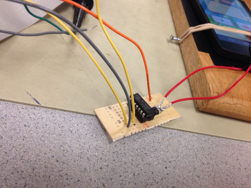
After a lot of experimentation, the following setup was found to be reasonably reliable:
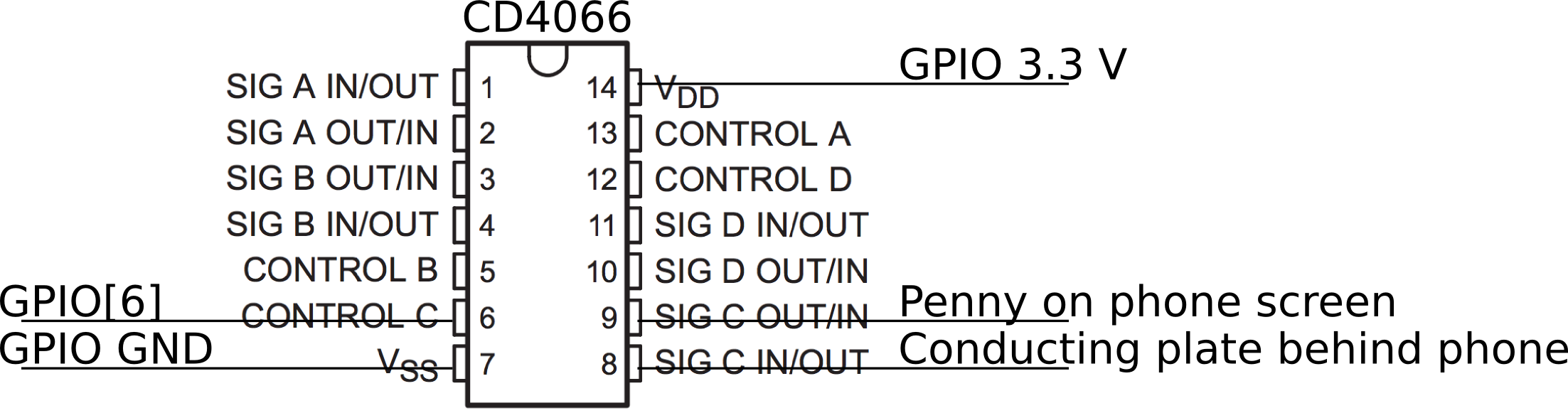
Quad Bilateral Switch Connection Diagram
As seen in the photo below, we made the hardware more reliable by using a PDIP socket and soldering it onto a solder board. While most of the pins of the CD4066 CMOS Quad Bilateral Switch was plugged into the PDIP socket, pins 8 and 9 were bent up and directly connected to the penny and conducting plate. We found this to make the tapping more reliable.
CD4066 CMOS Quad Bilateral Switch Connection
When GPIO[6] is set to high, the CD4066 CMOS Quad Bilateral Switch makes a connection between pins 8 and 9, which 'taps' on the screen. If GPIO[6] is left floating, CD4066 also makes a connection between pins 8 and 9, so the screen is also being 'tapped'. Hence, we found that it was important to keep GPIO[6] grounded as long as a tap is not desired.
Hardware/Software Tradeoff
Since the project is heavily dependent on speed of interfacing, computation and tapping, we decided to use a full hardware-based approach as acquiring the data and then interfacing it with software, doing processing and then sending back the tap command slow computation down and we were concerned that it may not have been able to compute fast enough to play the game.
Relationship with Existing Standards
There are no existing standards pertaining to our project.
Existing Trademarks
The game we are using is copyrighted by .GEARS studio. Our project does not infringe any patents or trademarks and merely uses the game for playing.
Hardware
We elected to use a full hardware based approach, with hardware performing calculations and making decisions for the taps. All the input and computations are done using verilog modules and the on board M9K block are used as primary storage elements. We also used some registers for storing the inputs between modules.
An overview of the hardware was provided above. In this section, we will be going into detail about the middle section, which handles computation and tapping, which is basically the modules between the two M9K blocks. We will explore these modules hierarchically.
The section in the middle consists of 4 major sub-sections:
- ThinkControl
- ComputeUnit
- Tapper
- VGA Side Seek M9K Blocks
ThinkControl
The ThinkControl module controls the overall operation of ComputeUnit and Tapper. This module is meant to be a 'think' operation by the FPGA player, who would then proceed to examine the locations of the bird and the pipes, and then decide whether to tap or not
Based on the input cycles_between_compute, a counter increments until cycles_between_compute has elapsed, and it then raises a compute_go signal. This results in the compute_go signal being raised at a periodic interval. This compute_go signal is used to trigger the ComputeUnit block.
The ThinkControl module also accepts a reply signal from Tapper. This signal tells ThinkControl that Tapper is done with its assigned number of taps, so that ThinkControl can reset the Tapper module. In addition to resetting the Tapper module, the reset_compute_and_tapper signal is also supposed to reset ComputeUnit, but in this implementation, ComputeUnit resets itself and does not need to be externally reset.
ComputeUnit
ComputeUnit manages one single 'thought cycle'. In one single 'thought cycle', the FPGA player makes two measurements of the positions of the bird, the pipe, and the gap, as marked by crosses in the diagram below.
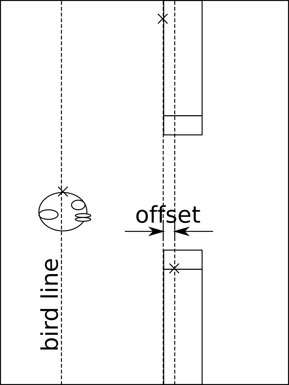
After getting the position of the bird at two different time steps, the FPGA player then uses the difference between the positions of the bird at those two time steps to predict the next position of the bird. Then, the FPGA player compares that predicted position with the threshold line that the bird is supposed to stay above, and taps if the bird goes below that threshold.
We believe that with these three points, the FPGA player should have enough information to at least get past the first pipe, even if it may face problems adjusting to gaps in consecutive pipes that differ in height greatly.
ComputeUnit uses DataStores, which are basically registers that only write when the en signal is high, and can be cleared. DataStores are also special in that they store a valid bit, to indicate whether the stored data is valid.
BirdSeek
The bird seek module is the first module for detection on the screen. When given the go signal, the BirdSeek module scans the phone screen along the line of the bird from the top until the top of the bird is detected. This module uses a line kernel with values {+1, 0, -1} and computes the correlation for every three pixels along the line. An edge is detected if the correlation exceeds the value 15.
Once the top of the bird is detected, it gives a done signal to the next module, HorzSeek, and also raises a valid signal that allows writing of the pixel position of the top of the bird to its Seek M9K block on the VGA side, as well as to a DataStore internal to ComputeUnit.
HorzSeek
The horizontal seek module is used for detection of the location of the first pipe. Once the bird seek module is completed, this module scans horizontally from the line of the bird to its right until the first pipe is detected. The principle used is the same edge detection from BirdSeek. Once the edge of the pipe is detected, its location is written to its own Seek M9K block on the VGA side and it raises a done signal which is then sent to the VertSeek module. The output of this module is also written to a DataStore.
VertSeek
The vertical seek module is used for the detection of the top of the pipe once the pipe is detected. This point is useful as the bird has to cross the pipe somewhere along this point to get past the pipe. Once the horizontal seek detects the edge of the pipe, the vertical seek reads the location from the read switch and starts scanning the screen from a small offset from the bottom of the screen along the detected pipe until the top of the pipe is encountered. The same edge detection algorithm is used here. After successful detection, the module raised a valid signal and writes the data to its own Seek M9K block on the VGA side. The output of this module is also written to a DataStore.
TapOrNot
The TapOrNot module is like the human part of ComputeUnit. When all the seeks are done twice and the sought pixel positions are valid, it combinationally predicts the next position of the bird and also calculates the threshold position of the center between the pipes using a mathematical unit (MathComponent) that handles all the signed calculations. If the bird is below the center between the pipes (can be calculated from the marked pixel since pipe gaps are always constant in height), it sends out a tap signal to the quad switch so that there is a tap and the bird is maintained along the center between the pipes. If the bird is above the center between the pipes, it does not tap and lets the bird fall. This should ideally guide the bird through the pipes.
ReadSwitch
The ReadSwitch is more like an arbiter that arbitrates access to the camera side M9K block. The seek modules express their requirement for data using the demand_0, demand_1 or demand_2 signals to ReadSwitch, and ReadSwitch grants access based on a fixed-priority scheme, where the higher the port number, the higher the priority is.
The lowest priority port is given to BirdSeek, followed by HorzSeek and then VertSeek. This policy is in line with the order they are run. Since HorzSeek should start only after BirdSeek is complete, if HorzSeek wants access, it should be given the priority. The same policy is applied between HorzSeek and VertSeek. In practice, this policy should not be exercised, since chaining of the done signals should ensure that only one seek module wants access at any one time.
If none of the seeks demand access to the camera side M9K block, the Copier gets access by default.
Copier
The copier module is a simple module to aid in display on the VGA monitor. It takes in the data from the M9K block on the decoder side and copies it to the M9K block on the VGA side. This module gets active only when the seek modules are inactive and not demanding access; otherwise, it is paused.
Control Unit
The above seeking process that happens twice is orchestrated by a control unit that takes compute_go as an input and works with BirdSeek to initiate seeks in BirdSeek, HorzSeek and VertSeek twice every time compute_go is raised. Between the first and second groups of seeks, STATE_DLAY is used to insert a delay so that there is a sufficient time between two readings of the bird's position for efficient prediction of the bird's next position.
A possible improvement to this module would be to also take into account prediction of pipe positions in the next time step, which would improve the player's performance.
Tapper
The tapper module is the interface between the computations and the GPIO port. The compute unit computes the number of times the screen should be tapped and sends it to the tapper module along with a valid signal.
This module contains a counter and a state machine that is shown in the diagram below.
This module is reset into STATE_WAIT. Upon receiving the valid signal indicating that the number of taps is valid, the number of taps is stored in a register. The state machine then transits to STATE_TAP if tap_times is positive. In STATE_TAP, the GPIO pin is held at 3.3 V, so the penny is shorted to the plate behind the phone and a tap is occuring.
At the end of the tap duration, the state machine transits into STATE_BETWEEN_TAPS, where the GPIO pin is kept at low voltage. This duration is required so that the phone can distiguish between two 'taps'. The number of taps left to go is decremented.
This repeats itself until the number of taps left is 1 and the tap duration expires. In this situation, the state machine transits into the done state, where it raises the done signal and waits for a reset. This done signal goes to ThinkControl, which in turn resets this state machine.
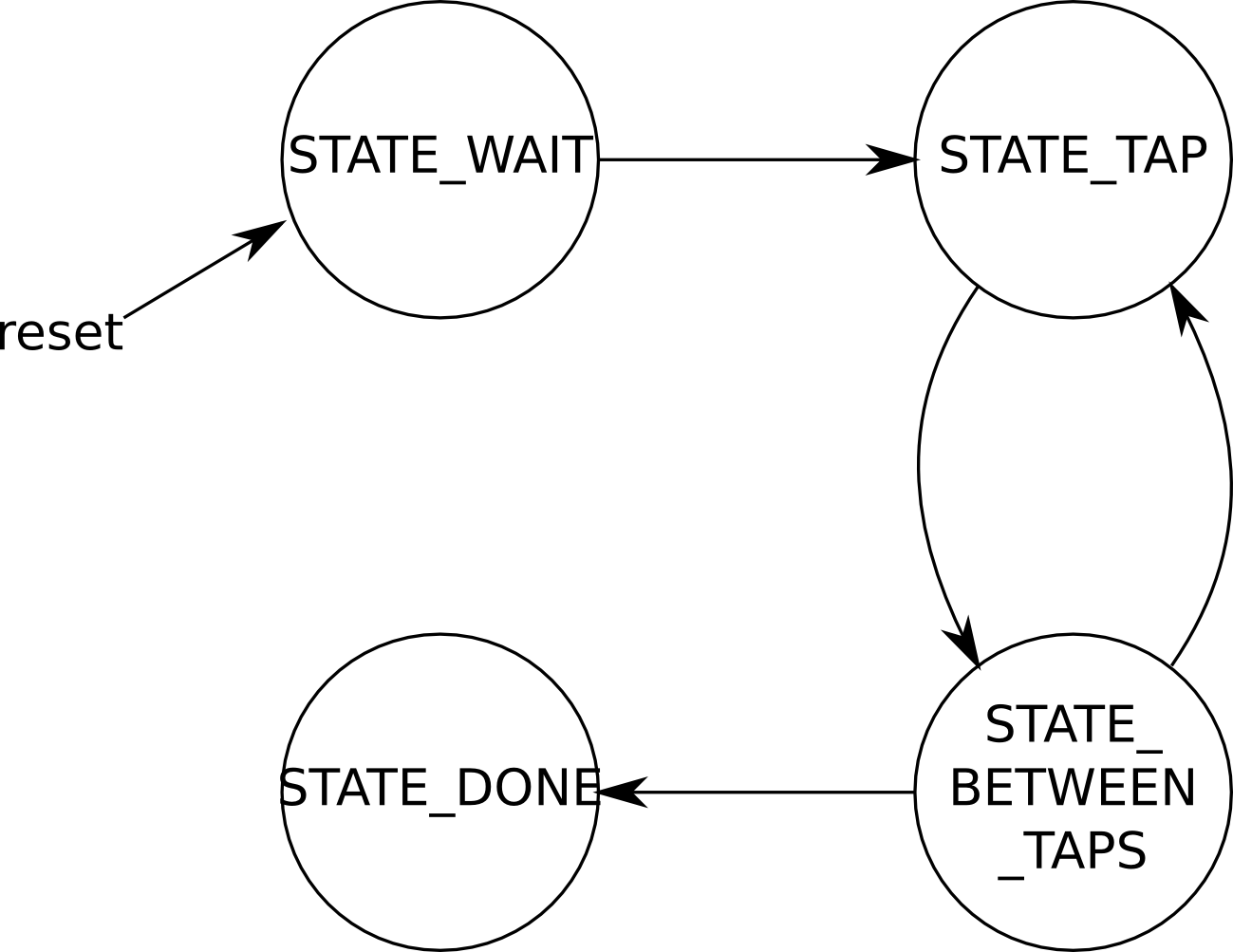
State Diagram of Tapper Module
VGA Side Seek M9K blocks
The M9K blocks on the VGA side are used to store the edge information found by each of the separate modules (Copier, BirdSeek, HorzSeek and VertSeek) within the compute unit, for display. We use M9K blocks because there is a need to separate clock domains here, to prevent glitchy output on the VGA monitor.
These individual blocks have just two locations in them. We wanted to have just 1 location, but the nature of M9K blocks requires a minimum of two addresses. Each of these M9K blocks contain just one word of data of size 10 bits, where the most significant bit contains the valid signal of the individual module and the lower bits contain the location of the edges detected by the individual modules.
The copier module has a separate M9K block which contains all the points on the screen that have to be displayed which is nothing but a buffer from the decoder to the M9K. The copier M9K has in all 512 x 256 pixels of information in them with the address being the Y and X coordinates and the data being the value of pixel information in that particular coordinate.
VGA Controller
The VGA controller was reused mainly from Lab4. It consists mainly of two counters, one that counts horizontally, and another that counts vertically. Both counters count on continuously.
The outputs, which are the v_sync and h_sync signals, are determined using a combination of the two counters’ values, based on the VGA specification. During the appropriate phases, as determined by the VGA specification, the output to the monitor is connected with the output of the pixel information of M9K block. The colours used are basically grayscale with varying intensities and hence output to the VGA's red, blue and green channels were all the same luminance value from the M9K block.
Software
The entire project is developed in hardware and there is no software component to this project.
Results
How well does it play Flappy Bird?
The FPGA player
- Gets the bird to the first pipe about 90% of the time
- Gets 1 point in the game approximately 10% of the time
- Gets 2 points in the game approximately 1% of the time
The top score it has achieved is 3 points.
Speed of Execution
In order to maximize the speed of execution of our project, we decided to use two different clocks. The data acquisition from the TV decoder, the M9K block read write and the VGA modules work at 27 MHz TV Decoder clock, which is their default frequency. The computation unit, which involves the read switch, the horizontal seek and vertical seek modules, uses the faster 50 MHz clock for its operation. The main purpose of having two clocks is that this allows the computations to be much faster for all the scanning and calculations.
The VGA and M9K blocks are operated at 27 MHz frequency which was used in the lab exercises before and they were working well as expected. The TV decoder captures the input from the camera and writes it to the M9K blocks at 27 MHz without any issues.
When these two clock frequencies were combined and used together, there were initially a few synchronization issues in the form of flicker as the two frequencies were not properly interleaved but this was solved by using M9K blocks between the two modules, since M9K blocks can support two different clock frequencies.
When the project was tested, the scanning algorithm and the edge detections were all working fine without any lag or delay but however, we noticed that the computations were actually too fast for the game to be played realistically as the program kept sending more than 10 taps per second which was causing the bird to rise more than what was required. To counter this issue, we introduced the module ThinkControl, which only triggers 'thinking' at a much lower frequency (10 Hz).
The detection of the bird and the pipes were being computed accurately in real time and the tap signals were being produced just in time for the bird to rise up or down in order to pass the pipes.
Accuracy
We can look at accuracy from a few different aspects:
Accuracy of Detection
The detection of the bird, the start of the pipe and the top of the pipe gap is quite accurate for the system. If we align the mobile phone in a correct fashion, the detection work well and we get all the points needed for calculation of the algorithm reliably.
Accuracy of Tapping
We tested the tapping mechanism before starting the project in a way that it continuous taps by generating a train of pulses on the GPIO and observing the taps seen on the screen. The accuracy of tapping is heavily affected by the frequency of tapping. If we tap at a very high frequency, the phone tends to ignore certain taps acting unresponsive. The lower the frequency, the better the accuracy of tapping. By the end of the project, we were able to tap reliably and all the hardware responded perfectly to tap attempts.
Accuracy of Algorithm
The accuracy of the algorithm was not as good as we expected. The game was more difficult than we thought it was. For example, a tap on the screen does not elevate the bird as much a drop descends it. This made the design of the algorithm very difficult because by the time a decision was made to tap and elevate the bird, it descends enough to lose the game. This area needs more work for the FPGA player to be better at the game.
Safety and Interference
The project had no safety considerations as the system works independently. The only interaction in the system is between the FPGA and the Mobile Phone. Also, there is no interference of our project with other people's designs.
Usability
The usability does not differ with different phones. The FPGA player should be able to work with any Android phone that also has a capacitive touch screen. A possible limitation is screen size. The FPGA player is designed using Google's Nexus 5, and it may have difficulty playing on phones with other screen sizes. The game can be made to play Flappy Bird on a phone with a different screen size by either changing the height of the camera or changing the code to look at a bigger or smaller region of the camera signal.
Conclusions
Results vs. Expectations
The results were promising as we got the scanning and detection of the pipe position and the bird position reliably. Also, we could tap consistently using the external circuit driven by the GPIO pin. The algorithm responded well to the arrival of pipes and movement of the bird.
The foundation for the game to be played reliably have been laid out effectively. Due to time constraints, we were unable to satisfactorily tweak the game-playing algorithm to play the game perfectly. Nevertheless, the game responds reasonably well to the algorithm implemented, and we can gain 1 point in about 10% of all games started. Given more time, we could have made the FPGA play the game even better, but nevertheless, we are satisfied with the strong foundation we built for playing the game.
If we were to do this again
Getting the algorithm for playing the game correctly was extremely difficult. If we were to do this again and get it all correct and reliable, we think that it would take at least an entire semester. The biggest issue we faced was probably understanding the mechanics of the game. It seemed like a simple game - a few pipes, a bird, a single control: tap, or not. However, the frequency of tapping and all the small details proved to be a tremendous hurdle.
A better approach might be to have the game emulated on an Android emulator that was connected to a computer program that could interact with the simulator by triggering taps on the screen, and could also read the pixels off the screen. That way, we would be able to find out how to play the game. Getting the game-playing algorithm working on the emulator would tell us exactly what pieces of information we require, and what order to process the information in.
After developing the game-playing algorithm in software, we should then be able to translate that software to custom hardware for the FPGA, which would let the hardware run much more efficiently. If the sequence of steps is too long and complicated, it might then make sense to build a simple custom microprocessor to step through the algorithm.
Taking this approach would have saved us hours of tweaking the algorithm in hardware, which was a slow and gruelling experience.
Intellectual Property Considerations
We used the Altera DE2-115 sample code for TV Decoder which also came with an audio output module. Our design instantiated various megafunctions which are generated using Quartus II, which includes the M9K blocks and the PLL modules.
Some fundamental hardware modules, such as registers, counters and muxes were adapted from Professor Batten's Verilog Components framework for ECE 4750
The game is the intellectual property of .GEARS studio, and we are in no way modifying the game source code for the project.
The project does not involve any trademark or patent issues, nor is subject to nondisclosure or intellectually sensitive materials.
Since we haven't developed the algorithm to play the game effectively, at this point of time we do not see any patent opportunities.
Ethical Considerations
This is just a game! There are little ethical considerations. Unlike the way Flappy Bird captured the hearts and minds of many and took their lives to crazy extremes, the FPGA player is merely a player.
Legal Considerations
As far as we know, there are no legal considerations involved with this project.
References
- Professor Batten's Verilog Components Framework from ECE 4750
- DE2-115 Sample Code for the TV Decoder
- CD4066 CMOS Quad Bilateral Switch Datasheet
- DE2-115 Manual
- Forum thread about tapping on the screen
- Youtube Video about tapping on the screen
- Flappy Bird Animation
Acknowledgements
We would like to acknowledge our advisor Prof. Bruce Land for the constant motivation and inspiration to think beyond the ordinary. We would also like to acknowledge the Spring 2014 ECE5760 TAs, Scott Mckenzie and Miles Pedrone, for their support.
Appendix
Code
Here's a link to our commented source code.
Task Distribution
- Ackerley Tng
- System Architecture
- Writing of Modules
- Tapping Mechanism
- Algorithm Planning
- Report Writing
- Ankur Thakkar
- Configuring M9K Blocks
- Writing of Modules
- Parameter Tuning
- Report Writing
- Saisrinivasan Mohankumar
- Module Code Adjustments
- Writing of Modules
- Tapping Mechanism
- Parameter Tuning
- Report Writing